Week - 4 - 2D meshing for Plastic components
MANUAL MID-SURFACE CREATION AND 2D MESH GENERATION
OBJECTIVE:
To create a manual mid-surface for the 3D model and generate the mesh.
PROCEDURE:
SEGREGATING GEOMETRY:
- Initially, geometry split into multiple surfaces regarding their geometry.
- Each surface locked with different views named with their thickness.
- Splinted surfaces then corrected for geometrical requirements.
- The surface which less than 0.5 are corrected or erased.
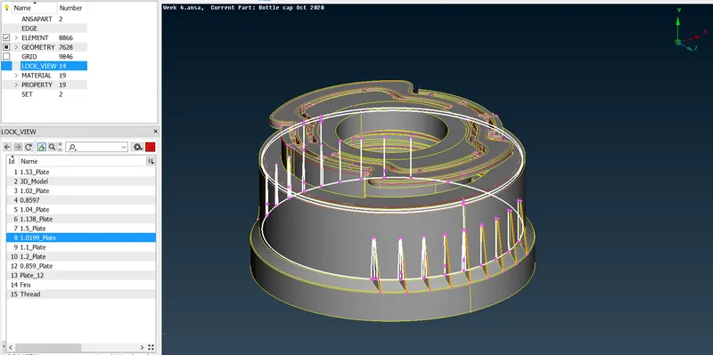
Pic:1 Geometry separated with respect to thickness.
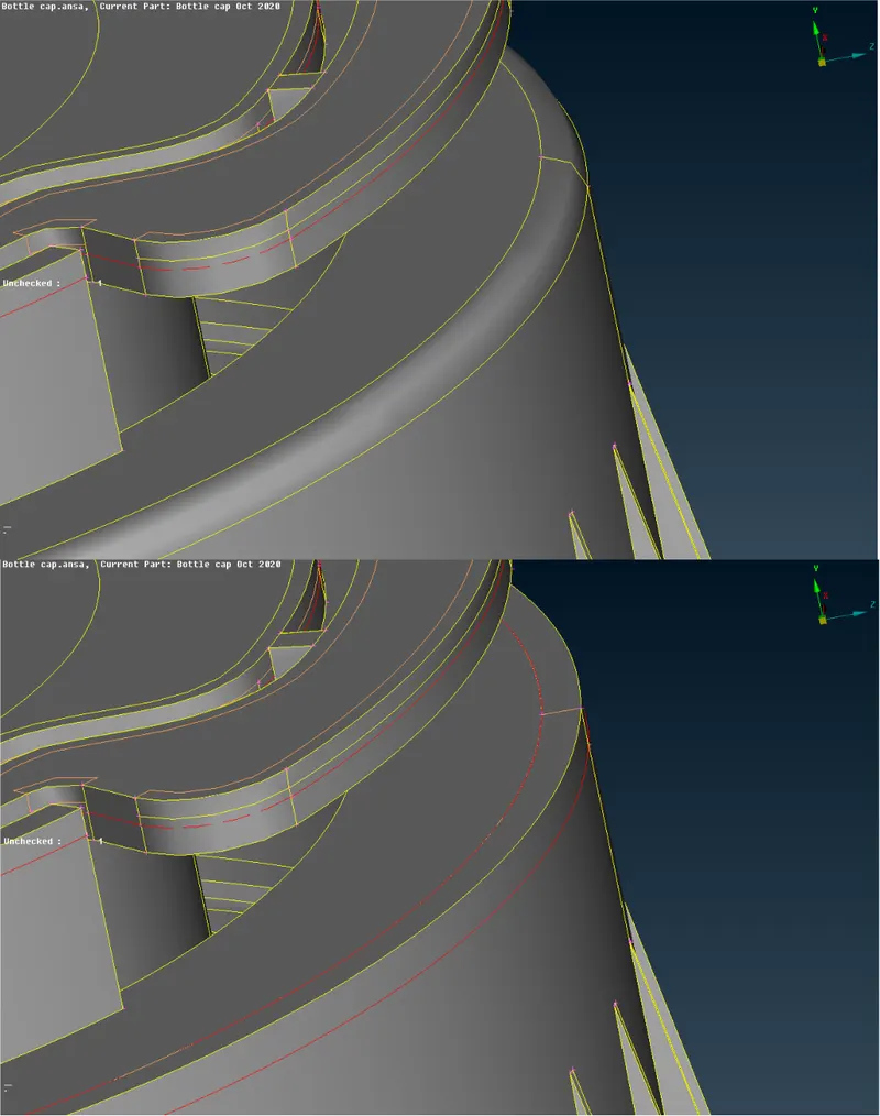
Pic:2 Surface correction
MANUAL MID-SURFACE:
- For each surface, one layer of the surface has been offset to its middle value of thickness.
- This process continued to all the view sets.
- After the creation of the mid-surface, each and every surface is connected with options like extend, interest.
- The final check for geometry has done an entire mid-surface saved in one lock view for meshing.
Fins:
- For fins, Curve -> middle option used to create a middle line on both ends.
- Then new surface created using those lines.
- This surface coon projected in the main surface and created contact between the main surface and fins.
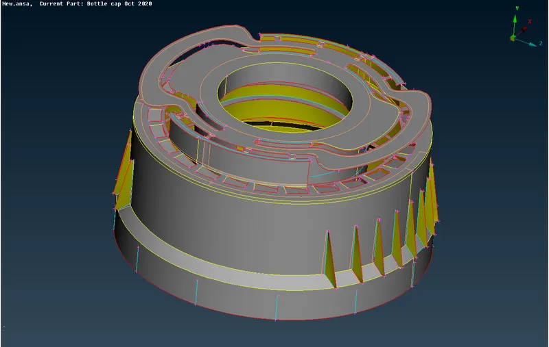
Pic:3 Manual mid surface.
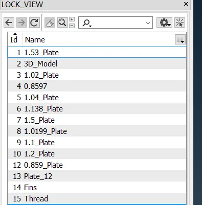
Pic:4 Final lock views
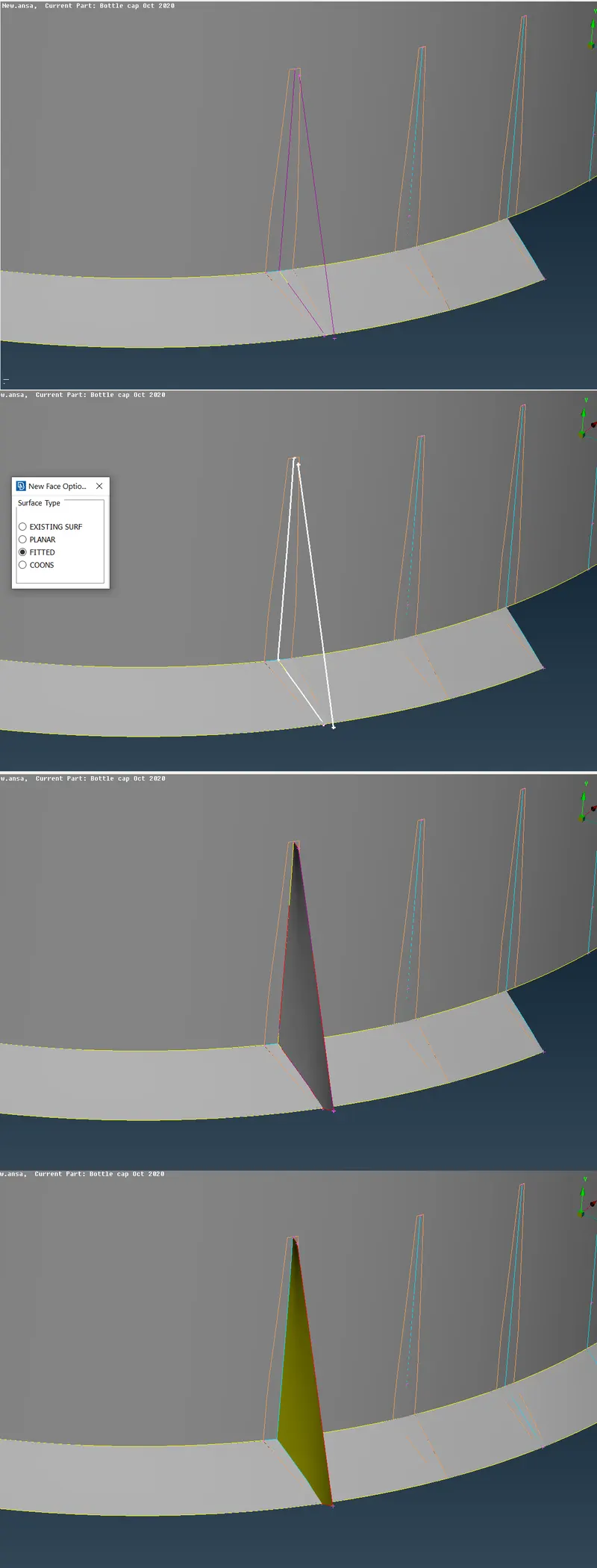
Pic:5 Fin surface
MESHING:
- Surfaces meshed with a tool named
- Then meshes are checked for quality criteria.
- In case any mesh has not satisfied with the quality value, then that mesh re-meshed with option
- After that mesh group are smooth by option known as
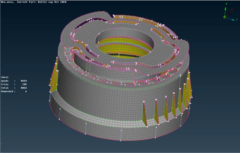
Pic:6 Mesh
PROPERTY ALLOTMENT:
- After completion of meshing, each surface view is assigned with property with thickness.
- Finally, mesh visual as 3D format and compared with the model.
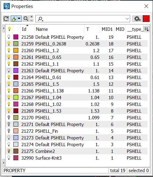
Pic:7 Property Page
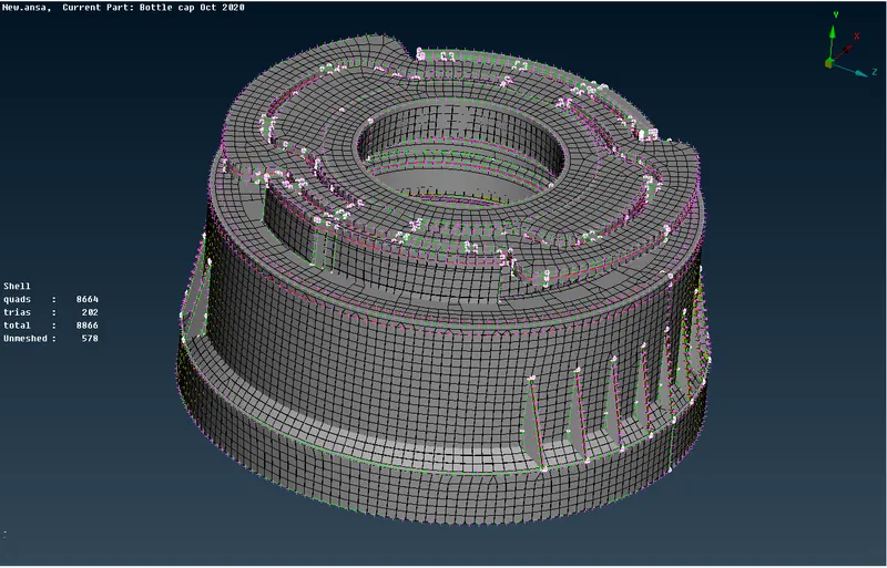
Pic:8 3D visual of elements
CONCLUSION:
Finally given model has been created with a middle surface and meshed with 2D Quad elements. Each surfaces allocated with a thickness of its own.