2D MESHING FOR PLASTIC COMPONENT (BOTTLE CAP)
2D MESHING FOR PLASTIC COMPONENT
AIM:
To Generate the mid surface for all the components after checking the geometrical errors and mesh the mid surface with the given element Quality criteria.
CAD MODEL:
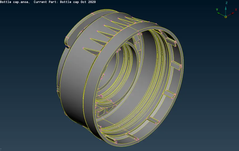
BOTTLE CAP
QUALITY PARAMETERS:
|
S.No |
Quality Criteria |
Value |
|
1 |
Target/Average length |
1 |
|
2 |
Minimum Length |
0.5 |
|
3 |
Maximum Length |
3 |
|
4 |
Aspect |
3 |
|
5 |
Warpage |
15 |
|
6 |
Skewness |
45 |
|
7 |
Jacobian |
0.7 |
|
8 |
Minimum Quad Angle |
45 |
|
9 |
Maximum Quad Angle |
135 |
|
10 |
Minimum Tria Angle |
30 |
|
11 |
Maximum Tria Angle |
120 |
|
10 |
Tria Percentage |
15 |
THEORY:
Why do we do Geometrical cleanup?
While we import any geometry data it generally comes up with little errors, some geometrical issues are
Surfaces are not stitched together i.e. (there is a gap present between the surfaces)
Very small surfaces are squeezed between the surfaces.
Sometimes duplicate surfaces are present
The junction between the two surfaces also contains gaps, overlaps, and misalignments.
In order to remove that issues and errors, we do geometry cleanup.
Mid-Surfacing:
Why do we create the Mid-surface?
While doing 2D meshing we extract the mid-surface from the model. Mid-Surface means the surface between the two surfaces. 2D meshing is carried out on the mid-surface because mathematically element thickness we assigned half in +Z axis (element top) and half in -Z axis (element bottom). Hence for appropriate representation of geometry via 2-d mesh, it is necessary to extract the mid-surface & generate nodes and elements on the mid-surface. We try to create the shell elements (one dimension i.e. thickness is significantly smaller than the other dimensions) which is a 2D representation of 3D elements. Mid-Surface meshing is used when the geometry thickness is very small as compared to its length and width, so we are generally used in most industries where the structure is made up of sheet metals and plastic, etc. In that cases, we use 2D elements instead of 3D elements, hence by adopting Mid-Meshing number of nodes decreases, and also computational time decreases.
We can extract mid-surface in two ways
- Manual mid-surfacing
- Automatic mid-surfacing
Here for the above component, we choose manual mid-surfacing because the given model is of plastic / cast one, so the thickness is not constant throughout, if we use automatic mid-surfacing and meshing it will not give us accurate results, users have to do a lot of changes in the model to repair, so that’s why we choose manual mid-surfacing, in manual mid-surfacing we use the offset option to create middle surface
During meshing, we have to take care about
- The feature should be captured properly.
- No back-to-back trias.
- There should be element connectivity between the elements.
- No opposite trias.
- No rotational quads.
- Quality check to ensure that all elements are of good quality.
PROCEDURE:
IMPORTING FILE:
- Import the given model Files ->open->Bottle Cap.ansa
CHECK GEOMETRY:
- Check the geometry by selecting Tools_checks_geometry and clear the error
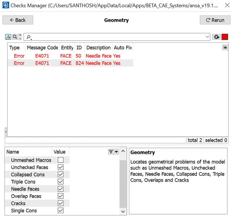
To clear these errors we can go with Both manual and automatic fixes, here I fixed with the automatic Fix option.
MIDSURFACE EXTRACTION:
The next step is to extract the mid-surface. Initially, the mid-surface is extracted for the cylindrical-shaped surfaces at the middle of the model. The option used for extracting the mid-surface is "middle", in faces from the topo module.
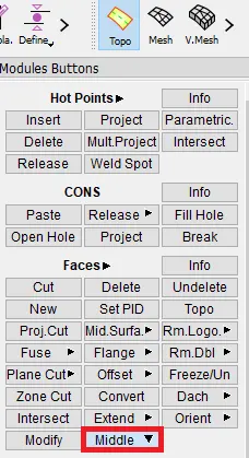
Then the adjacent surfaces are selected. After selecting two surfaces, in between to which the mid-surface should be obtained.
By clicking "OK" after accepting the surfaces, the mid-surface will be generated. The obtained mid-surface appears as shown in fig.
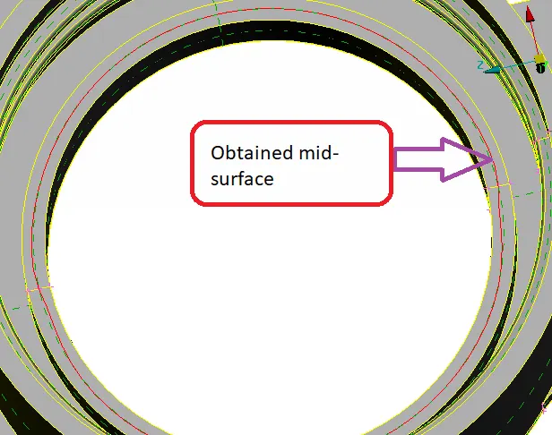
The obtained mid-surface can be only seen by using the "NOT" boolean operation. And by selecting "PID region". Then by selecting any surface of the parent, the mid-surface will be only shown in the graphical display. As shown in fig
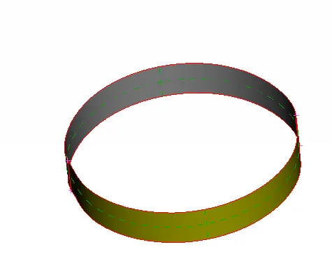
Then the top part which is horizontal is isolated, as shown in fig. To obtain the mid-surface.
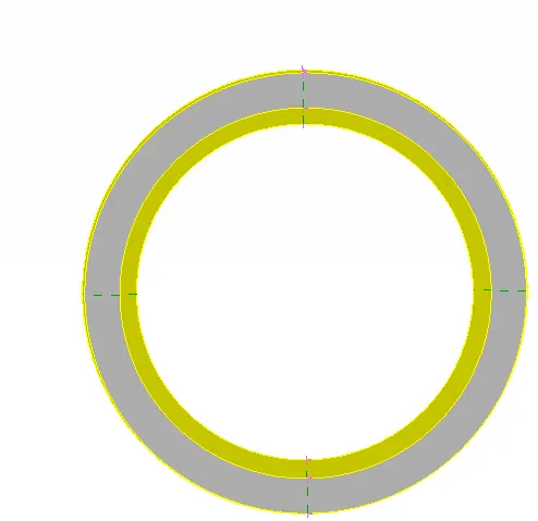
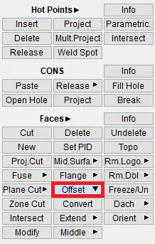
For extracting the mid-surface, another option named "offset" in faces from the topo module is used. As shown in fig
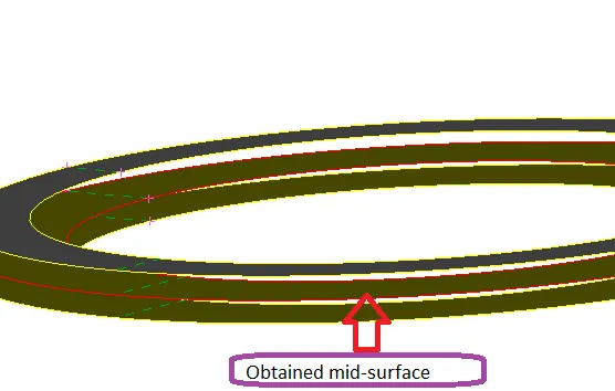
The obtained mid-surface is isolated as shown in fig In order to check whether the obtained mid-surface is achieved properly or not.
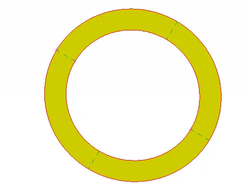
Then the mid-surface is taken for the substrate. The option used for taking the mid-surface is "offset". The outer surface of the parent is selected to offset. And the obtained mid-surface appears as shown in fig.
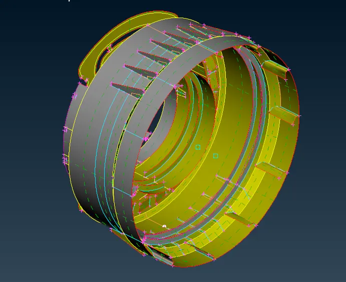
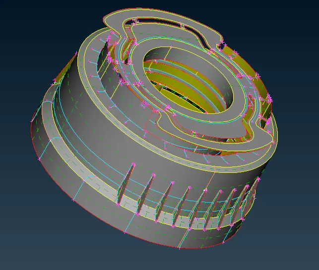
The final mid surface for the bottle cap is obtained as shown in the below figures.
MESHING:
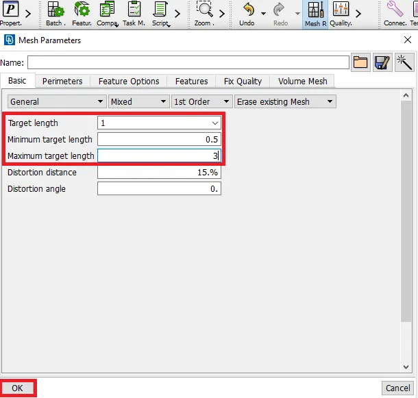
Before meshing, the mesh parameters should be specified.
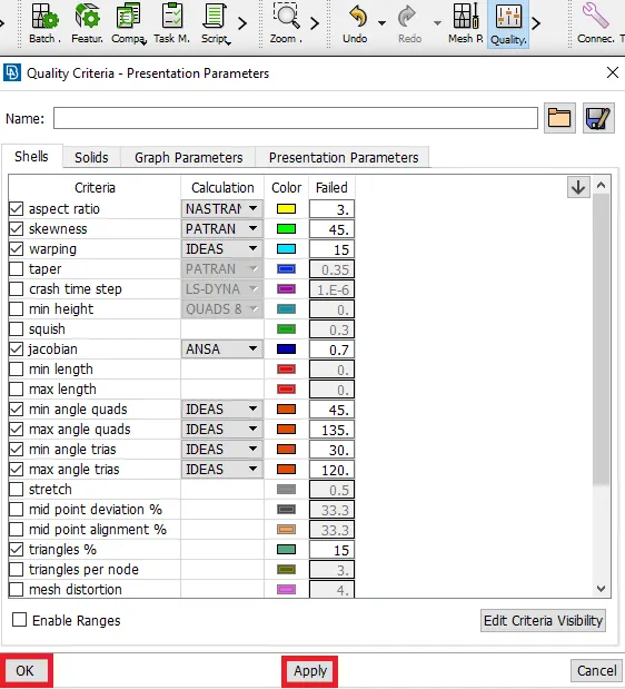
Then the quality criteria should be specified. The criteria required should be enabled & entered values. After specifying the values, by clicking "Apply" & "OK". The quality criteria will be assigned.
Note: All settings, mesh parameters, quality criteria will be there only for a session. Whenever closed & opened the session, they need to be specified again.
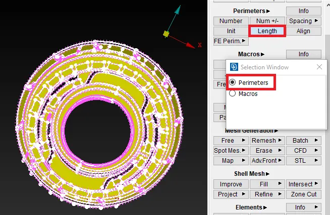
Then the length between the perimeters should be specified. Which will be equal to that of target element length. Then the faces are selected.
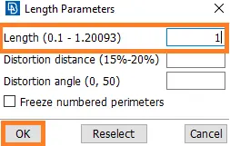
The target element length will be entered in the dialog box, as shown in fig. In order to specify the length between the perimeters. Then by clicking "Ok", the perimeter length will be specified.
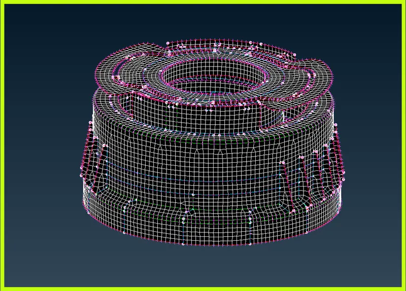
The meshed component is shown below.
Assign Thickness to the Components
- Go and assign thickness to the components.
- Go to properties browser and double click on the component to which you want to assign the thickness, A new window will pop on the GUI. Give thickness value there.
- Similarly, do the same process for every component.

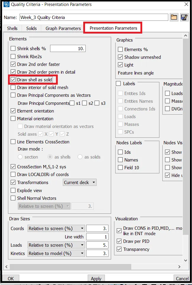
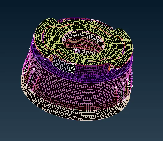
- After Assigning Thickness, Check whether the thickness has been applied or not.
- To check Go to Utilities >> Quality Criteria >> Presentation Parameters >> Draw Shell as Solid.
Final Model Image:
LEARNING OUTCOMES:
- Extracting the mid-surface for the plastic(Varying thickness) components. By using various options like the middle, offset, multi in middle & with the help of curves.
- Meshing the geometry.
- Reducing the off elements by using various tools such as smooth, reconstruct & paste.
- Assigning the various thicknesses by creating the PID's.
CONCLUSION:
- Extracted the mid-surface for the given bottle cap model.
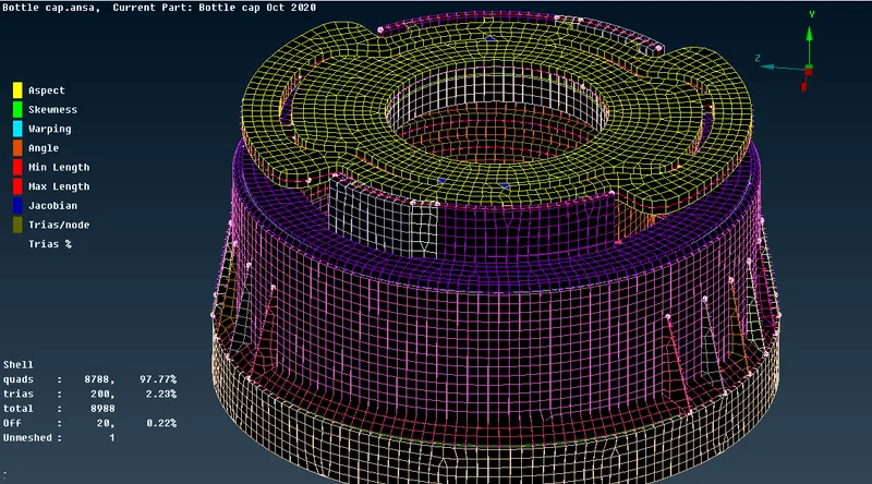
- Finally, Generated a 2D mesh on the extracted mid-surface. By maintaining the quality criteria mentioned above.
- Assigned the thickness.