Control logic of the Washing machine and Gear shift mechanism using Stateflow
AIM: To implement the control logic of the Washing machine and Gear shift mechanism using Stateflow.
OBJECTIVE:
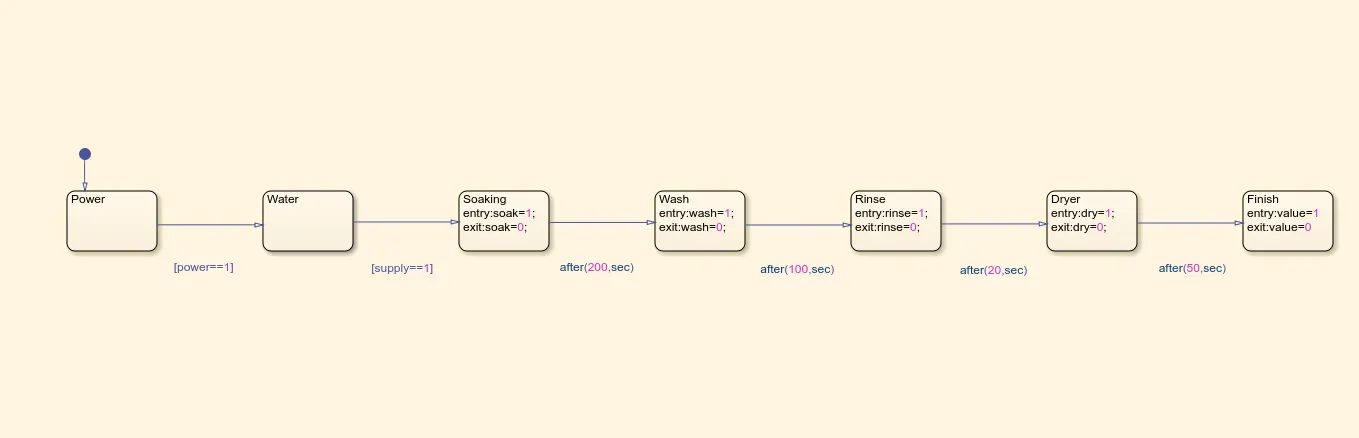
1. To implement control logic of a washing machine using Stateflow as per given sequence:
- If the power supply is available, the system gets activated
- If the water supply is not available, stop the process and indicate through LED
- Soaking time should be 200s followed by Washing time of 100s
- Then rinsing happens for next 20s and dryer runs for 50s
- After all the processes have completed turn on the finished LED
2. Make a Simulink chart for the gear shift logic as per below conditions:
speed input while the simulation is running and display the gear number.
| Speed Range (kmph) | Gear |
| 0 to 15 | 1 |
| 16 to 25 | 2 |
| 26 to 40 | 3 |
| 41 to 60 | 4 |
| 61 Above | 5 |
1.To implement control logic of a washing machine using Stateflow
THEORY:
Stateflow: Stateflow provides a graphical language that includes state transition diagrams, flow charts, state transition tables, and truth tables. It is used to describe how MATLAB algorithms and Simulink models react to input signals, events, and time-based conditions. Stateflow enables you to design and develop supervisory control, task scheduling, fault management, communication protocols, user interfaces, and hybrid systems. With Stateflow, you model combinatorial and sequential decision logic that can be simulated as a block within a Simulink model or executed as an object in MATLAB. Graphical animation enables you to analyze and debug your logic while it is executing. Edit-time and run-time checks ensure design consistency and completeness before implementation.
Control Logic: Control logic is a key part of a software program that controls the operations of the program. The control logic responds to commands from the user, and it also acts on its own to perform automated tasks that have been structured into the program. Control logic can be modeled using a state diagram, which is a form of hierarchical state machine.
PROCEDURE:
A washing machine by spinning at 800-1600 rpm helps soap and dirt with it to leave the surface of the cloth via centrifugal force and into outlet pipes hence utilizing centrifugation to both clean and partially dry the clothes loaded in it. Thus the processes are electrically controlled, such as the drum, valves, pump, motor and heating. The valve opens again and the dirty water drains out of the drums. The pump works to help get rid of the water. The valve lets clean water in again into the drums. The four process are:
SOAKING:
It is used to dip clothes in detergent water to remove dirt from the clothes. In this function customer need to select soak from a panel. Soak - This function is available with wash timer, In 42 min of washing 27 min is soak and 15 min machine will wash the clothes.
WASHING:
During the wash cycle, a large plastic agitator (green) turns around, moving your clothes through the water. When the wash is finished, the pump drains the water from the outer drum.
RINSING:
The dirty, soapy water is drained, then the washing machine is refilled and your clothes are "rewashed" in clean water. Spin: All the water is drained completely, then your clothes are spun very fast and excess water is removed thanks to centrifugal force.
DRYER:
They work by pushing warm dry air through your wet washing to extract moisture, then cooling the now humid air in a heat exchanger to condense the moisture, which is collected in a tank or pumped down the drain. The (now dry) air is reheated and the cycle repeats.
SIMULINK MODEL:
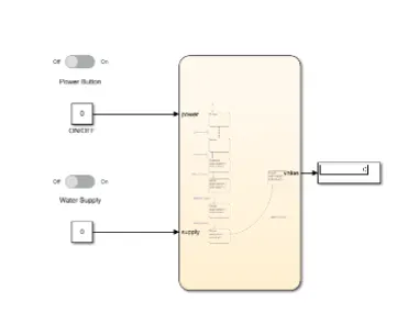
Control logic:
Stateflow:
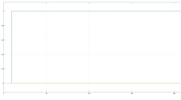
Result:
2. Make a Simulink chart for the gear shift logic as per below conditions:
Control logic:
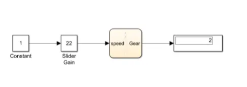
Here when the stimulation is running we have to vary the speed and according to the speed display the gear number.
Explanation:
- Slider Gain block: It is used to vary the speed. For a slider block there should be an input for that constant block is introduced. Output is connected to the chart block.
- Constant block: The value in the constant block is multiplied with the current value of slider gain. Here constant value is 1.
- Chart block: It represents the Stateflow of gear shifting according to the conditions.
- Display block: To display the current gear for the respective speed.
Explaining the Stateflow:
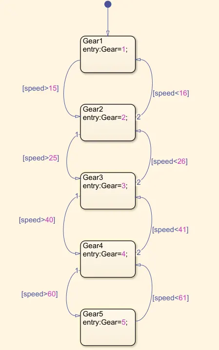
- Speed is the input and gear is the output for the stateflow.
- In 1st sate it will check if speed>15 if true transition happens to the 2nd state else the gear number is displayed.
- In 2nd state there are 2 transitions happening 1st it will check if speed>25 if true transition happens to the 3rd state, in transition 2 it will check if speed<16 if true it passes to 1st state if both conditions are false the gear number is displayed.
- In 3rd state there are 2 transitions happening 1st it will check if speed>40 if true transition happens to the 4th state, in transition 2 it will check if speed<26 if true it passes to 2nd state if both conditions are false the gear number is displayed.
- In 4th state there are 2 transitions happening 1st it will check if speed>60 if true transition happens to the 5th state, in transition 2 it will check if speed<41 if true it passes to 3rd state if both conditions are false the gear number is displayed.
- In 5th sate it will check if speed<61 if true transition happens to the 4th state else the gear number is displayed
Result:
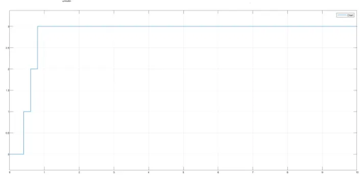
CONCLUSION: Hence, the given problem was simulated for the washing machine and gear shift mechanism and executing the Stateflow as per according to given conditions.