Week - 4
Aim: Create a simulink model for:-
- Implement control logic of a “washing machine” using State flow as per given sequence:
If the power supply is available, the system gets activated
If the Water supply is not available, stop the process & indicate through LED
Soaking time should be 200s followed by washing time of 100s.
Then rinsing happens for next 20s & dryer runs for 50s
After all the processes have completed turn on the finished LED
Solution:
Stateflow is a control logic tool used to model reactive systems via state machines and flow charts within a Simulink model. Stateflow uses a variant of the finite-state machine notation established by David Harel, enabling the representation of hierarchy, parallelism and history within a state chart. Stateflow also provides state transition tables and truth tables.
Control logic is a key part of a software program that controls the operations of the program. The control logic responds to commands from the user, and it also acts on its own to perform automated tasks that have been structured into the program.[1]
Control logic can be modeled using a state diagram,[3] which is a form of hierarchical state machine. These state diagrams can also be combined with flow charts to provide a set of computational semantics for describing complex control logic
Washing machine:
Working Principle of washing machine is centrifugation-
Centrifugation is a separation process which uses the action of centrifugal force to promote accelerated settling of particles in a solid-liquid mixture.
The washing machine consists of centrifuge for this purpose. A centrifuge is a piece of equipment that puts an object in rotation around a fixed axis, applying a force perpendicular to the axis of spin that can be very strong.
It is basically consist of following steps:
- Soaking
- Washing
- Rinsing
- Drying
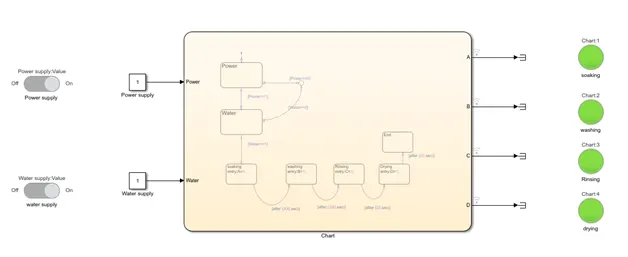
Here is the state flow diagram which showcases these four steps:
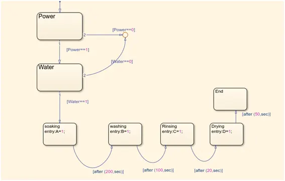
Simulink model
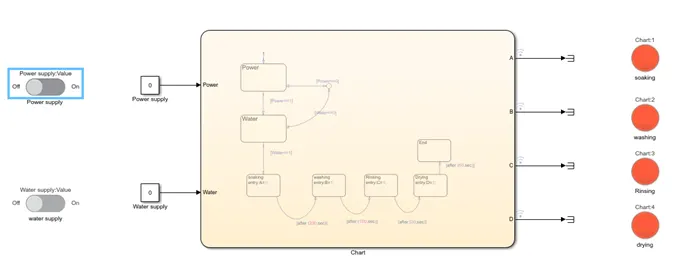
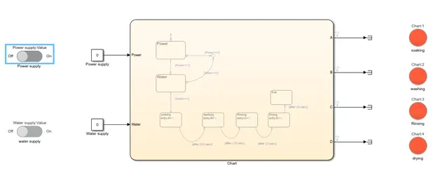
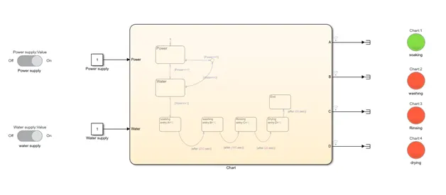
As we have provided two inputs here, there are following conditions to observe,
1.Water supply=0, Power supply=0, t=0sec
- Water supply=1, Power supply=1 (soaking)
3.Water supply=1, Power supply=1, t= after 200sec (washing)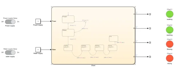
- Water supply=1, Power supply=1, t= after 100sec(Rinsing)
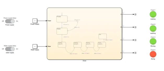
- Water supply=1, Power supply=1, t= after 20sec(drying)
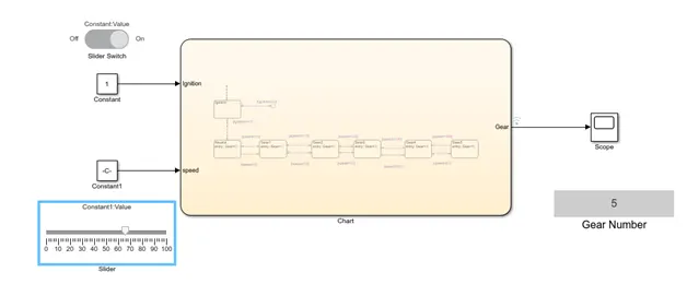
2.Make a Simulink chart for the “Gear shift” logic as per below conditions:x
Speed Range (kmph) Gear
0 to 15 1
16 to 25 2
26 to 40 3
41 to 60 4
Above 61 5
Give speed input while the simulation is running & display the gear number.
Solution:
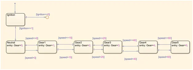
State Diagram for above problem:
Simulink model:
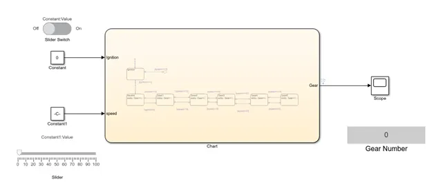
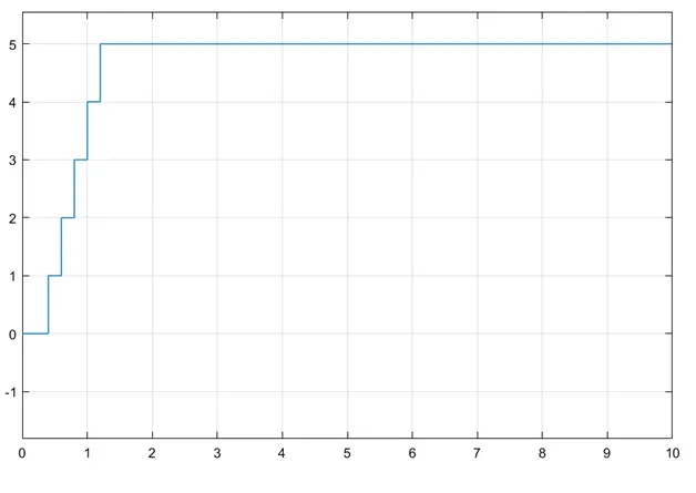
Lets observe the change of gear with respect to speed
Speed 0-15 , Gear 1
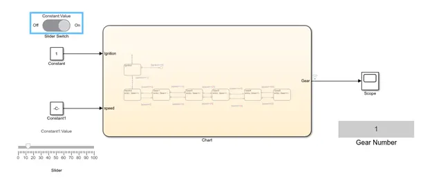
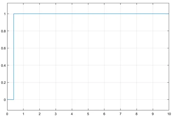
Speed 16-25 , Gear 2
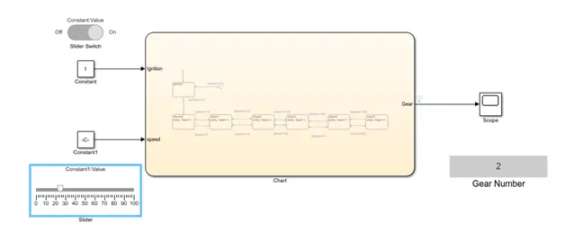
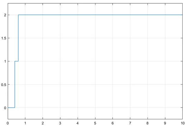
Speed 26-40 , Gear 3
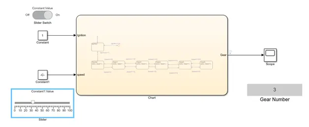
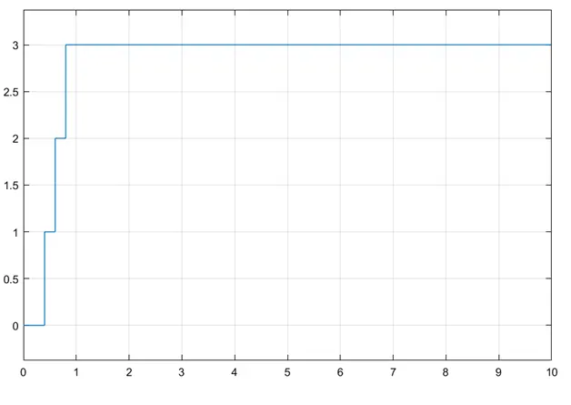
Speed 41-60 , Gear 4
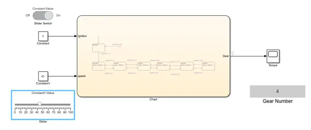
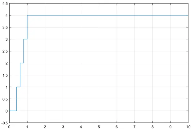
Speed- above 60 Gear 5: