Week 4.2: Project - Transient simulation of flow over a throttle body
AIM
To Determin Transient Simulation OF Elbow with variable valve Position Using Converge
INPUT
BOUNDARY CONDITION
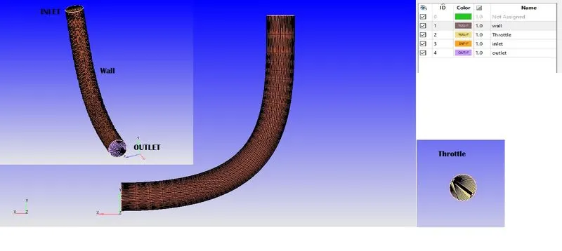
Predefine mixture-Air
Simulation Parameter
Solver: Steady-state
Simulatio mode- Fully Hydrodynamic
Simulation Time Parameter
End Time-0.01 S
Init-time step-1e-09 s
min-time step-1e-09 s
Max-time step-1
Max-Convection CFL-1
Time output calculation
# time step
v=200
l=0.2
#Flow rate
dt=l/v
t=10*dt

print('End Time=',10*dt)
#number of file needed for output
nt=50
dtn=t/nt
print('Time interval 3D output=',dtn)
Solver Parameter
Convection CFL in Final Stage-0.5
BOUNDARY
INLET PRESSURE:1.5e5 Pa
OUTLET PRESSURE:1e5Pa
Throttle-wall
motion type: Rotating
Surface movement: moving
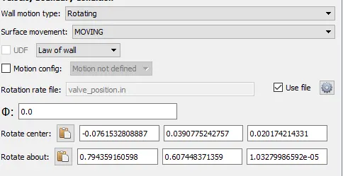
Setting Trottle as referance
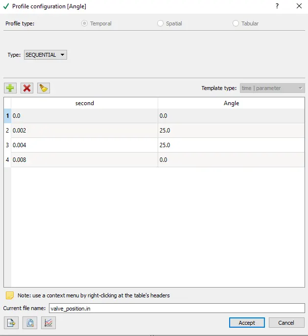
Profile moving
0 S=0
0.002S=25
0.004S=25
0.008S=0
wall-wall
Region & Intialisation
Create Region Species-air
Grid Controls
Base Grid-0.02
Fixed Embedding
Entity type-Boundary
Boundary ID-Throttle
mode-Permanant
Scale-1
Embadded Layer-2
for Fine layer in around Throttle
run setup with no hydrolic condition to check the solution
OUTPUT
valve mesh motion
slice with function of time
MASS FLOW outlet
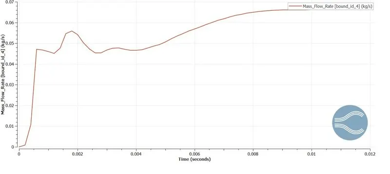
Pressure outlet
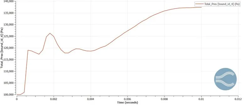
Velocity outlet
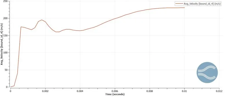
Pressure contour
Velocity contour
Total elbow physics Effect
Valve motion Effect Contour varation
Conclution
Transient flow valve motion analysis is Done using Converge
Higher Pressure loss in flow from initial 0.001 to 0.004 S after 0.006 s that there is an increase in pressure this is due to effect of thottle motion and flow become almost reaching steady in flow
The effect of Pressure and velocity loss is clearly view in contour in effect of Thottle where flow seperation accours so there is variation of physics