Week 4.2: Project - Transient simulation of flow over a throttle body
Aim:
To run Transient state simulation for the flow over a throttle body using converge.
Objectives:
-
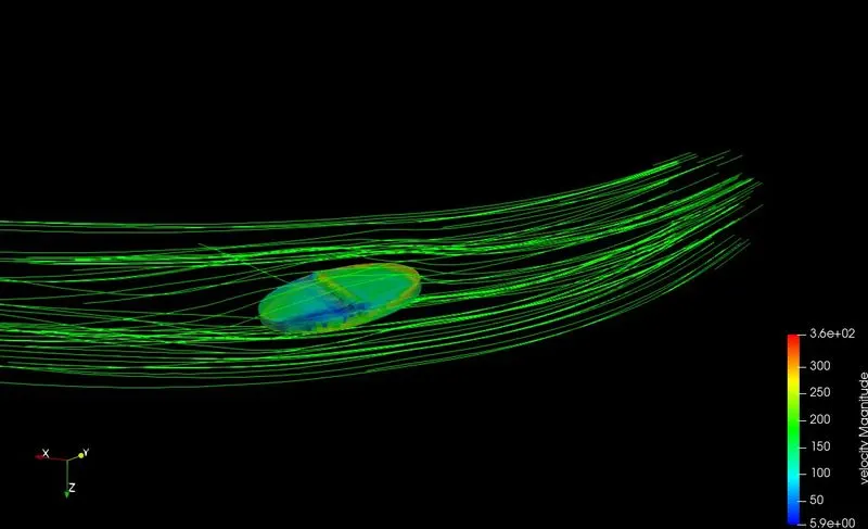
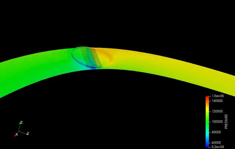
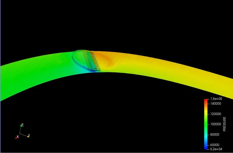
Post process the results and show pressure and velocity contours.
-
Show the mesh (i.e surface with edges).
-
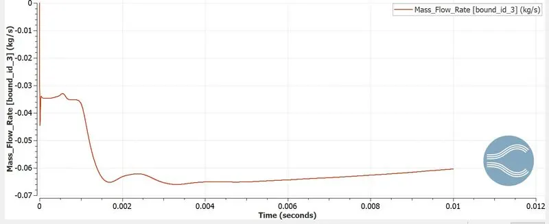
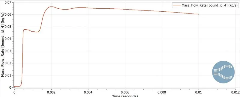
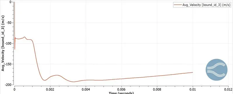
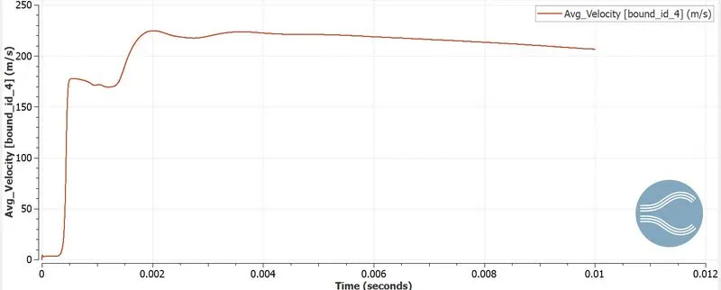
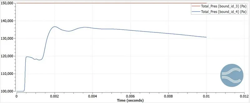
Show the plots for pressure, velocity, mass flow rate and total cell count.
Introduction:
The throttle body is an important part of your air intake system that controls the air flowing into your engine. It's located between your air intake and engine manifold where fresh air is pulled into the engine for the combustion process.
Model:
Case Setup:
1) A geometry for the throttle flow is imported in converge studio.
2) The necessary boundary conditions are defined.
3)The necessary steps are then followed in setting up the case where materials, simulation parameters, initial conditions, physical models etc are all specified.
4) Base gride size & embedding is also specified
The boundary conditions are applied to the surfaces as follows:
Inlet :
Pressure:150000 Pa
Outlet :
Pressure:100000 Pa
Elbow:
Wall
Law of wall
Throttle:
Wall
Rotating wall
Law of wall
Geometry:
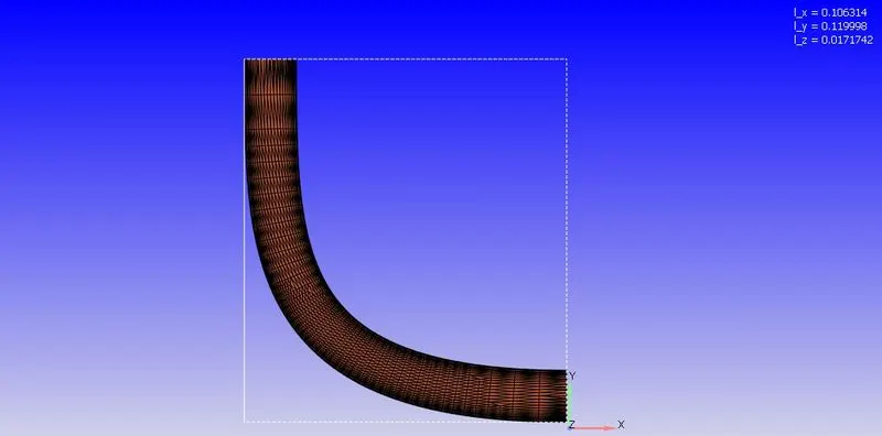
Throttle:
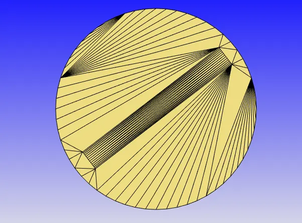
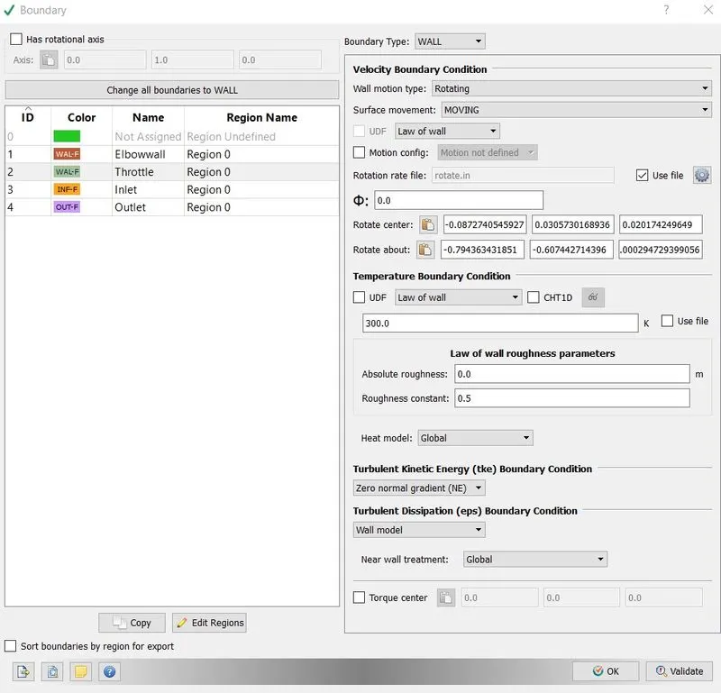
Centre: -0.0872741 0.030573 0.0201742
Normal: -0.794363 -0.607443 -0.000294729
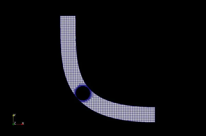
Mesh:
Gride size:
dx-dy-dz=2e-3
Embedding:
Scale :2
Embedding layers: 2
Contours:
Velocity contour:
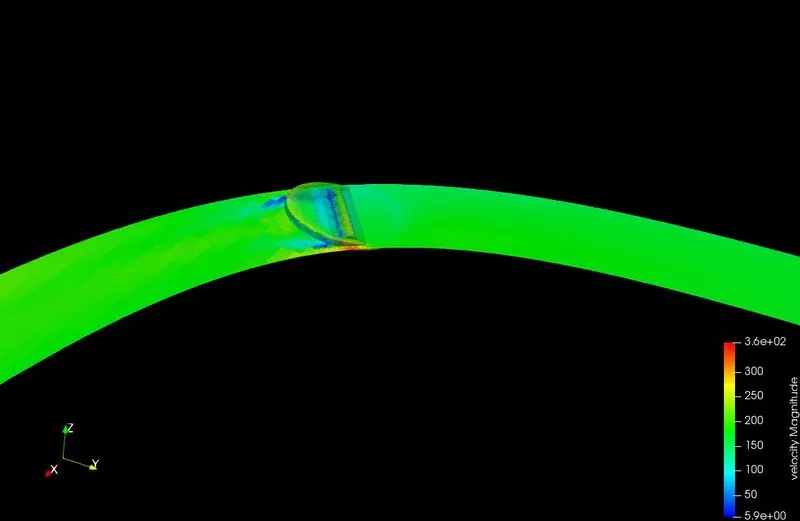
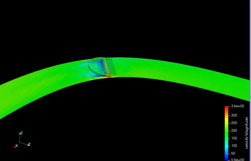
Velocity Streamline:
Pressure contour:
Plots:
Massflow:
Inlet MassFlow:
Outlet MassFlow:
Inlet AvgVelocity:
Outlet AvgVelocity:
Pressure:
Totalcells:
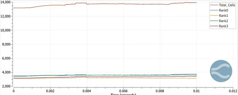
We can see that since the throttle valve remains in the 25 degrees angle position from 2-4ms, and in zero degrees angle position after 8ms, the mesh geometries remain unchanged for that time step. For the remaining time steps, the mesh geometry, and hence the total number of mesh elements change with respect to time.Due to the rotation of throttle plate,wake region is formed on plate causing decceleration of flow leads to separation of flow hence decrease in static preassure at outlet.