Week 4-1D Element Creation Challenge
AIM :
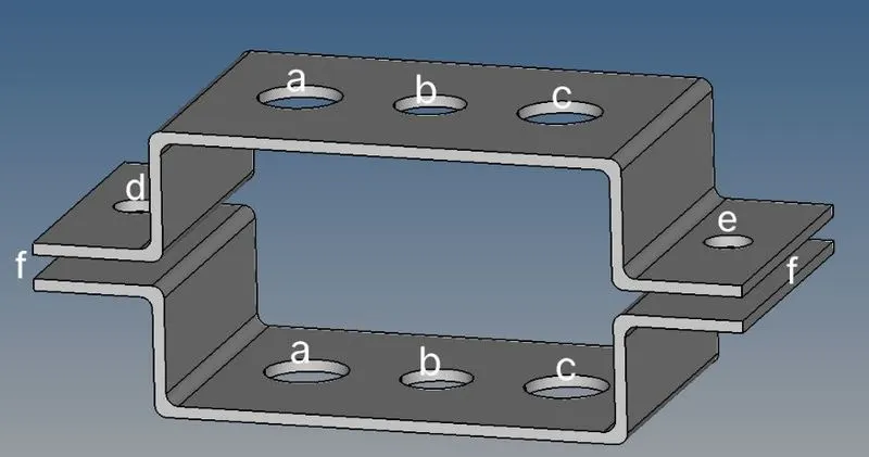
To Mesh the Given component with the Size of 5 Units. Create 1D elements on the following component with given cross-section and DOF.
OBJECTIVE:
a. Rod element:- Translational DOF should be Constrained with RBE2 link
Cross-Section: BOX- Dimension a= 12 mm
dimension b=10 mm
Thickness t= 0.75 mm
b. Beam element:- All DOF should be constrained with RBE3 link
Cross-Section: I Section- Dimension a= 8 mm
Dimension b= 10 mm
Dimension c= 8.5 mm
Thickness t1= 0.75 mm
Thickness t2= .6 mm
Thickness t3= .6 mm
c. Bar element:- Constrain only x and y DOFs With RBE3 link
Cross-section: X section- Dimension DIM1= 5 mm
Thickness DIM2= 1.2 mm
Dimension DIM3= 10 mm
Thickness DIM4= 1.2mm
d. & e. Apply the mass of magnitude 10 with the RBE2 link
f. Join the two components with Spring elements
CAD MODEL:
PROCEDURE:
First of all we need to import the geometry,the file type is in IGES.
Go to File >> Import-Geometry >> (Select file) >> Import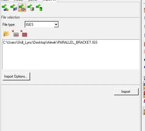
After importing the object if it is solid or any surface it will be in wire frame mode.we have to make into shaded view so we can see the entire components.
Then we are going to create a mid suraface,
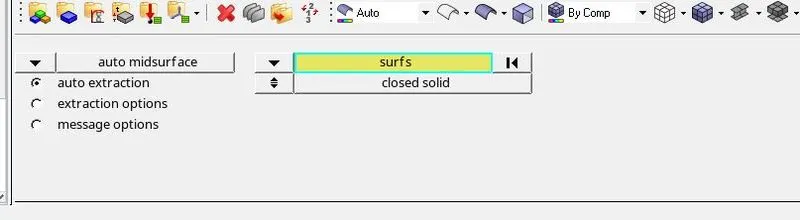
Goemetry>midsurface>and select surface and click extract to create a midsurface.
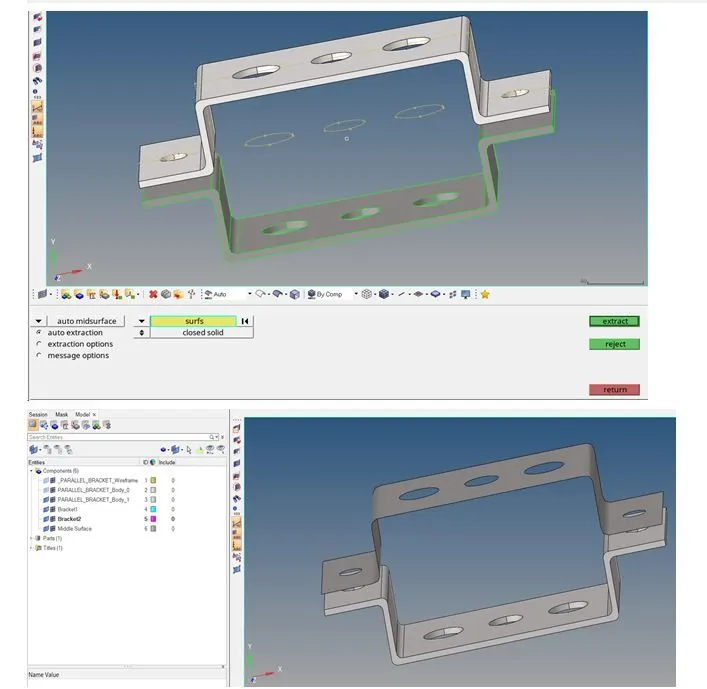
Then create midsurface for lower bracket and rename it,Delete solids by Selecting delete<solids<all<delete.
Rename the midsurfaces as bracket 1 and bracket 2,and hide the surface,assign material by right click<create<material<steel<return.
create properties for bracket1 and bracket2
create<properties,click on this properties and assign thickness 5 and keep element type as shell and add material
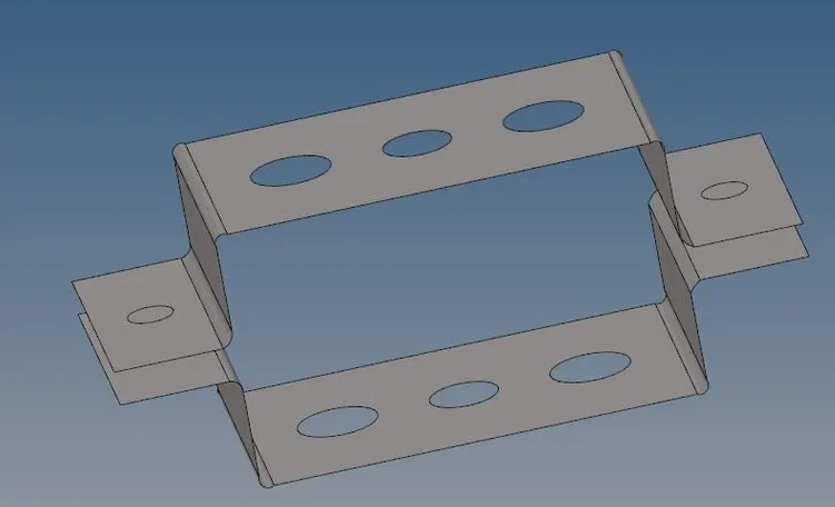
the output will be like this after the solids removed we need to add a washer split at the holes for these splits gives us the better mesh flow and rigidness at the holes.
So inoder to give washer split
Geometry>quickedit>washer split>give the offset value as 5mm, click the hole were we need the washer split.
The output will be,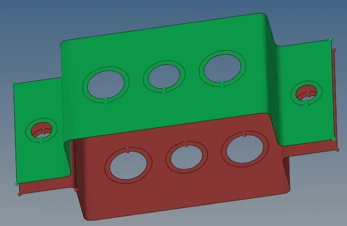
After creating the washer split we need to create a mesh on the object.
So we need to mesh inoder for that 2D> automesh >Select the surfaces and give the element size as 5mm and mesh.
the output will be,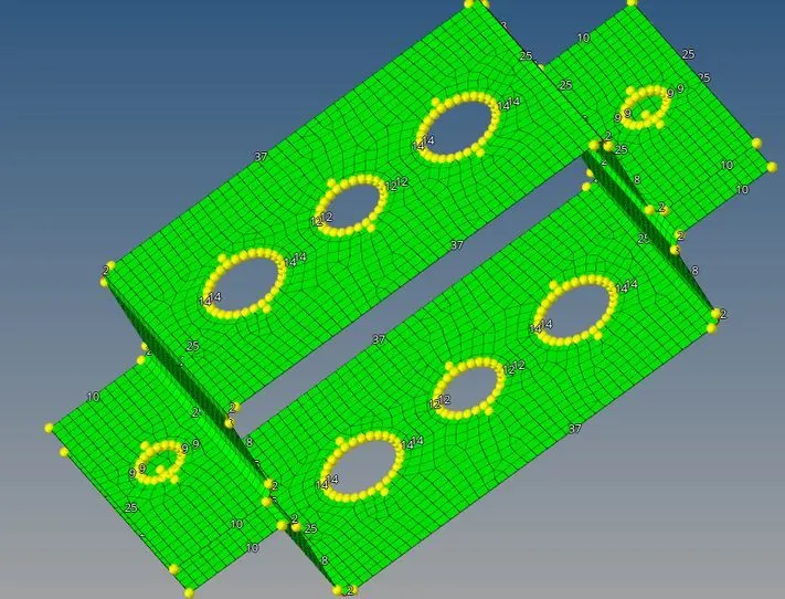
So we need some element adjustments in the model near the washer split. By left mouse click we can increase the number of nodes and decrease using right mouse click.
So after arrange all the nodes finish and return.
This is the meshed object.
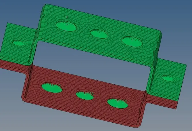
So then we need to create 1D element for the given model with the given cross section and DOF's so for the given component at a location we need to create rod element by taking translational Dof's as the constraints with RBE2 link. so first create RBE2 link at the location.
So now go to 1D >rigids> calculate node>multiple nodes> click on nodes and select nodes by path and click mouse on the model to create nodes near the circle.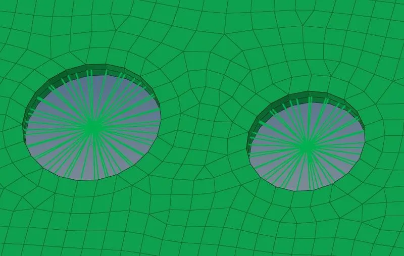
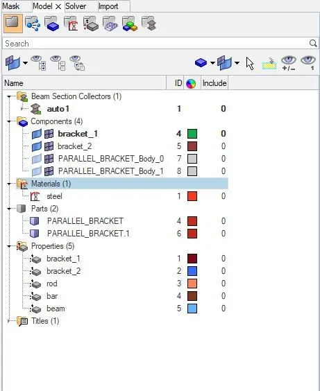
click the mouse right button on components section and select the material to add it for the component, It will be renamed to bracket1 and also create another property as bracket2.Go to components section and delete the first three components.To rename the midsurface is bracket 1 and another bracket 2,and set the properties to required specifications.
Rigid elements are mostly RBE2 elements. These elements have infinite stiffness. These elements never bend, rotate, or move. In RBE2, the load distribution is uniform irrespective of the position from the load.
In RBE3 elements, the load distribution depends on the distance from the load. Load distribution is more on the nodes closer to the load.
After creating RBE2 and RBE3 links we need to create 1d elements in hypermesh.
First of all creating a rod on 'a'
1D>rods>select nodes> select element type as CROD.
the given below is the output for creating rod on 'a'.
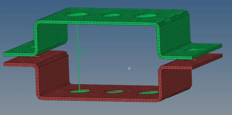
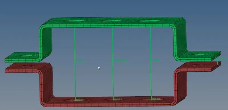
after that create a bars 'b' and 'c' so we need to go 1D>bars >select nodes >orientation >element type(CBEAM or CBAR)
then create the bar and beam on b and c.
So at last we need to create section in hyper mesh.
Go to 1D>Hyperbeam>Standard Section and choose kind as thin-walled box and click on produce.
then a new window will open in that window we can add the dimensions as per the requirements that given in the solution.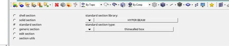
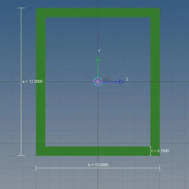
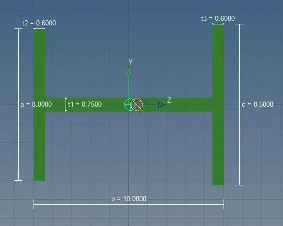
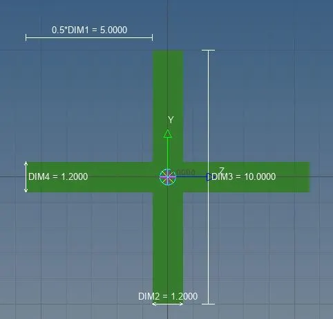
Add the given properties to rod ,beam, bar and assign the cross section to them.
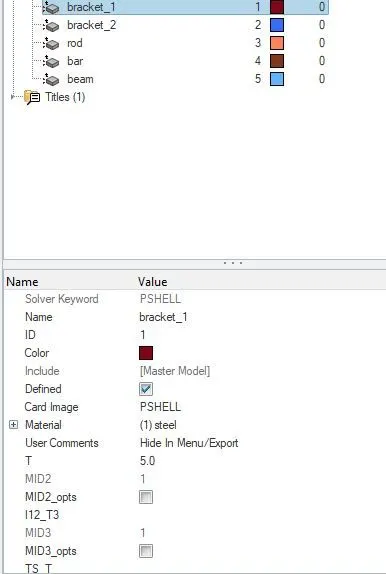
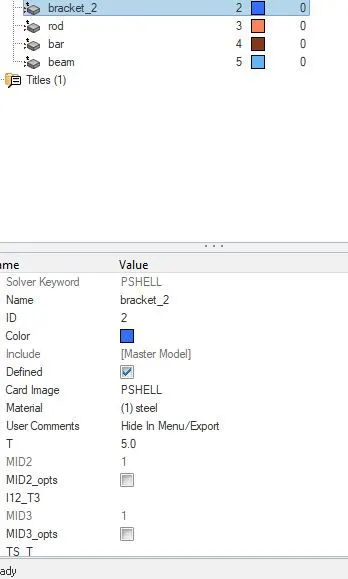
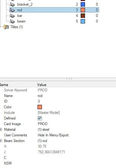
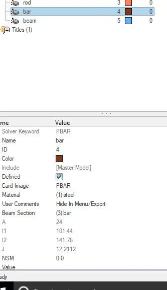
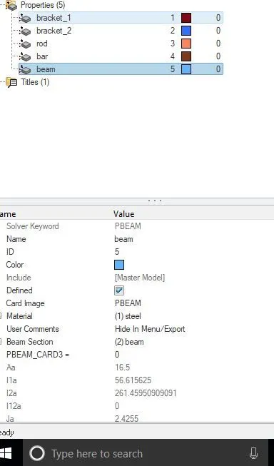
After all we need to update beam bar and rod,Set properties of rod,beam and bar,Go to update the elements.
In 1D select the rod click on the element and set property element type option.
Click on the update,
Repeat the same process for beam and bar elements.
Click on the return button.
After that the last procedure we need Apply the mass at d. & e of magnitude 10 with the RBE2 link.
Creating masses at ‘d ’and 'e' points.
Select rigid and create RBE2 as shown in above points.
Go to masses and click on the RBE2 node give mass 10,Click on create it will be applied mass.
Repeat the steps for another side point.
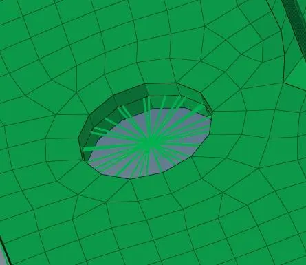
Create springs at ‘f’ point.
Select 1D on the main menu bar. Go to springs select the node 1 & node 2.
Click on the element type as CELAS1 spring and click on the create.
repeat the steps for another side.
CONCULSION:
Hence we had done all the solutions to be done in this problem.
we had done the mesh with the given component with the Size of 5 Units.Create 1D elements with given cross-section and DOF