Week 4-1D Element Creation Challenge
AIM :
To Mesh the Given component with the Size of 5 Units & to Create ID elements on the following component with the given cross-section and DOF using Hypermesh Software.
OBJECTIVE:
- Import the geometry, extract the Mid-surface, and Mesh the given geometry with the size of 5 units.
- Create a 1D element on the component with the given cross-section & DOF using HYPERMESH GUI.
SOFTWARE TOOL USED :
Altair HyperWorks Version 2022
GIVEN DATA :
a. Rod element:- Translational DOF should be Constrained with RBE2 link
Cross-Section: BOX- Dimension a= 12 mm
dimension b=10 mm
Thickness t= 0.75 mm
b. Beam element:- All DOF should be constrained with RBE3 link
Cross-Section: I Section- Dimension a= 8 mm
Dimension b= 10 mm
Dimension c= 8.5 mm
Thickness t1= 0.75 mm
Thickness t2= .6 mm
Thickness t3= .6 mm
c. Bar element:- Constrain only x and y DOFs With RBE3 link
Cross-section: X section- Dimension DIM1= 5 mm
Thickness DIM2= 1.2 mm
Dimension DIM3= 10 mm
Thickness DIM4= 1.2mm
d. & e. Apply the mass of magnitude 10 with the RBE2 link
f. Join the two components with Spring elements
THEORY :
1. Geometry Clean-up :
Designers have different priorities while creating CAD geometry than analysts who are seeking to use the data. Usually, a single smooth surface is divided into smaller patches, each of which is a distinct mathematical face. And often, there will be gaps, overlaps, or other alignment issues at the junction of two surfaces.
In geometry cleanup, analysts integrate several faces onto a single smooth surface to make the geometry more suitable for meshing. This enables the creation of the elements across the entire region at once and eliminates the need for false or unintentional edges in the finished mesh.
Some commands for the geometry cleanup are as follows :
- Geometry -----> Edge edit -----> Replace
- Geometry -----> Surfaces -----> Ruled
- Geometry -----> Quick edit -----> Filler surface
2. Meshing/Mesh generation :
Mesh generation is the process of discretizing the entire model into smaller elements in other words Mesh is a network that is formed of cells and points. Meshing is often used in FEA and CFD domains.
There are two types of meshing, 2D Mesh & 3D Mesh. In 2D Mesh, the mid surface is extracted from the component and then meshing is done on the mid surface whereas in 3D Mesh, direct meshing is done on the component from inside out. The difference between the 2D & 3D mesh is that the mesh type in 2D Mesh is mixed whereas in 3D Mesh the mesh type is Ortho tria ( for complex regions such as fillets and hemmings) or Tria ( For regions that are flat and not as complicated ).
3. Difference between RBE2 and RBE3 element :
|
RBE2 |
RBE3 |
|
It is a rigid element and all the nodes are constrained. |
Nodes can be moved and can be translated where the load is applied. |
|
Load distribution is uniform. |
The node close to mass will have more load than the node farther from the node where the load is applied. |
|
RBE2 elements cannot have materials. |
RBE3 elements can have a material assigned. |
4. Difference between Rod, Bar, and Beam :
|
|
ROD |
BAR |
BEAM |
|
Based on the area of cross-section |
Circular |
Non-circular like rectangular, square, I section bar, etc |
It can be of any shape either circular or rectangular, square, etc. |
|
Based on the type of loading |
Axial load is irrespective of compressive or tensile but it should not be torsion or bending. |
Axial load is irrespective of compressive or tensile but it should not be torsion or bending. |
It can be subjected to any load such as tensile, compressive, etc. |
PROCEDURE :
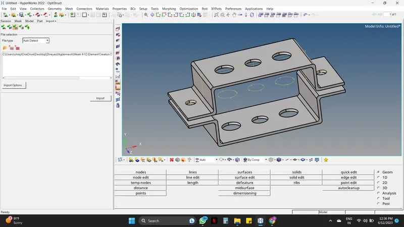
Step 01 : Importing CAD Model.
- The initial step is to import the geometry into HYPERMESH Software.
Import Model -----> Import Geometry -----> File type - IGES ----> Select Location -----> Click Import -----> Fress F to fit the model.
Step 02 : Geometry cleanup
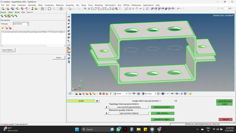
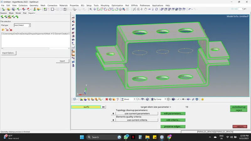
Geometry -----> Autocleanup -----> Mouse right-click on Surfs and select all ----> Autocleanup.
Step 03 : Mid-surface generation
- The mid surface is generated to reduce the complexity as by simplifying the cad model we get more accurate simulation results in a shorter time.
- In Hypermesh there are many ways to extract the mid surface, an engineer must try to take the exact mid surface on every edge, curve, and complex area. Capturing the exact mid-surface is important because it can later lead to irregular mesh flow and quality issues during meshing.
The following approaches are some methods to extract mid-surface.
- Offset Approach.
- Offset + planes + sweep Approach.
- Offset + planes Approach.
- Skin Offset Approach.
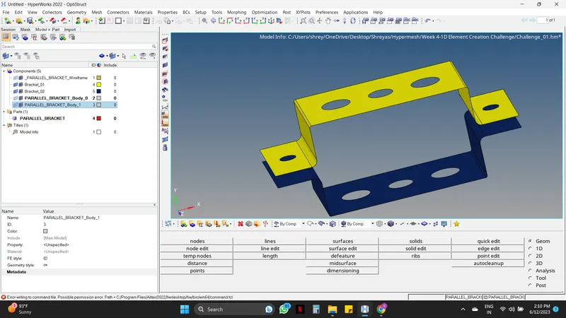
Here in this particular component, Skin Approach will be the best fit as it can Capture all the edges properly.
Skin Offset Approach :
Geometry -----> Midsurface -----> Automidsurface ----> Select the Extraction options and in that Skin Offset -----> Now select auto extraction again -----> Select the bracket one by one -----> Extract.
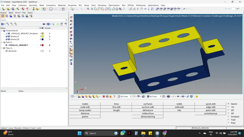
Step 04 : Deleting the Solids
- After creating the midsurface the solids must be deleted.
Components -----> Right-click on the component which needs to be deleted -----> Delete.
Step 05 : Creation of Washer Split.
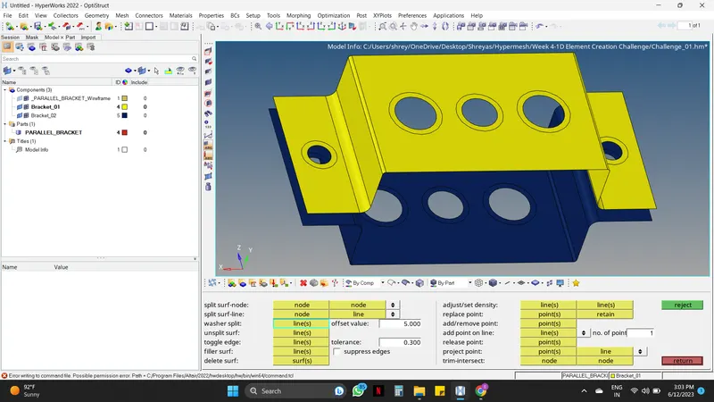
- Creating the washer splits at the holes as these splits will give better mesh flow and rigidness at the holes.
Geometry -----> Quick edit -----> Washer split and enter the offset value as 5mm ----> Select the holes which need the washer split.
Step 06 : Creating and Assigning the Properties and Materials.
- Here two new properties and one material must be created for assigning them to the component.
For creating properties :
Mouse right-click on the Tab area -----> Create -----> Property.
For creating Material :
Mouse right-click on the Tab area -----> Create -----> Material.
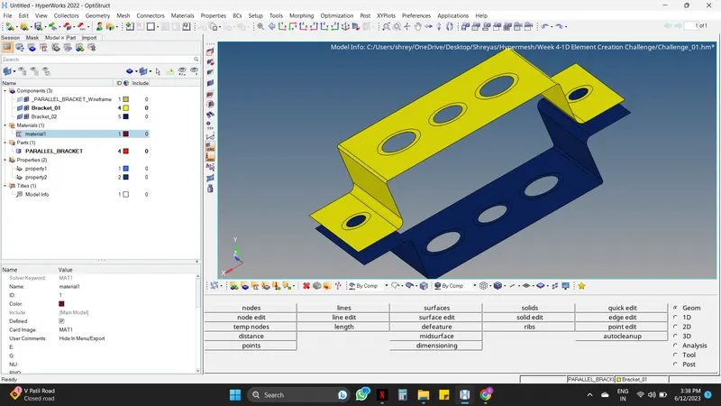
- Now for assigning them to the bracket follow the steps given below.
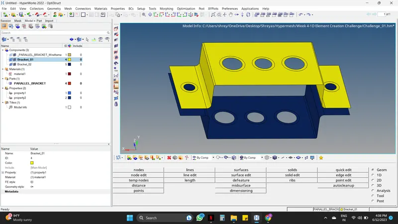
Mouse Left click on the Bracket_01 in the Tab area -----> Asign the property and material in the Message bar.
- Do the above same steps with Bracket_02.
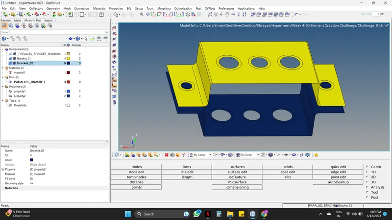
Step 07 : Mesh Generation
2D -----> Automesh -----> Enter element size as 5mm ----> Mouse Right-click on the Surfs and Select displayed -----> Mesh.
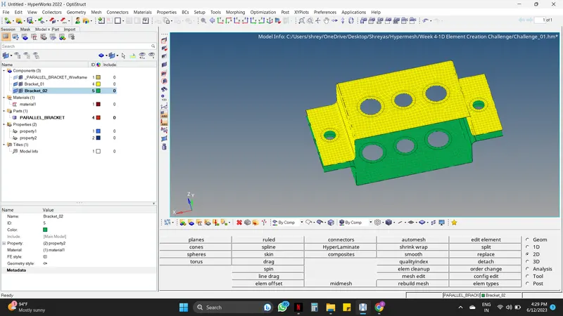
( NOTE : Here the color of the Bracket was changed from blue to green for proper visibility of the mesh )
- After the generation of the Mesh Quality index must be checked, Since there is no Quality index given engineer can move forward.
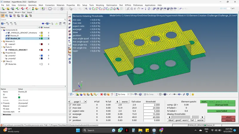
Step 08 : Creating Connections
Follow the below steps for RBE2 Connection :
1D -----> Rigids -----> Select Calculate nodes on top nodes option ----> Select multiple nodes on the bottom nodes option -----> Mouse right-click on the bottom nodes and select By Path -----> Select the Nodes for connection -----> Create.
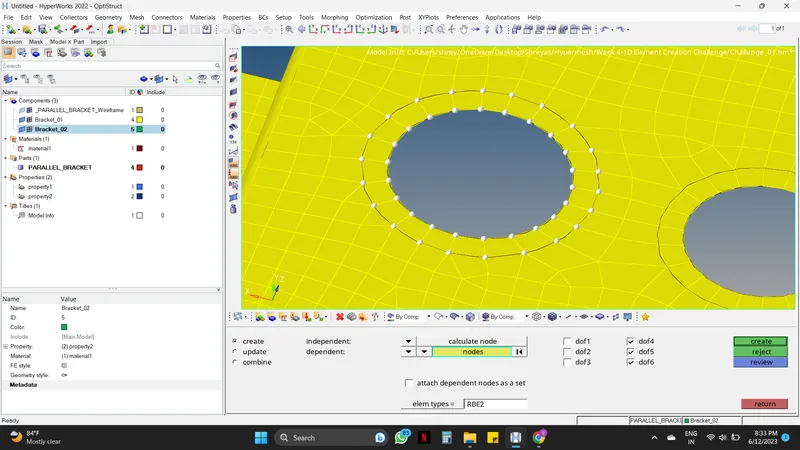
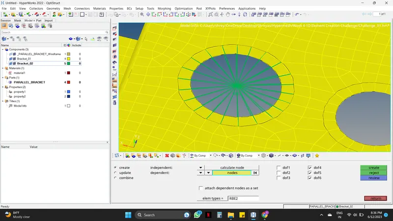
- As mentioned in the given data RBE2 connection must be created on a,d, and e hollow sections.
- The below fig shows the RBE2 connection at "a hollow section" where the Translational DOF is Constrained with the RBE2 link (dof 1, 2, and 3 are unchecked)
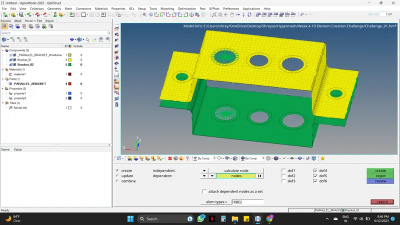
- The below fig shows the RBE2 connection at "d & e hollow section".
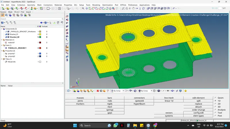
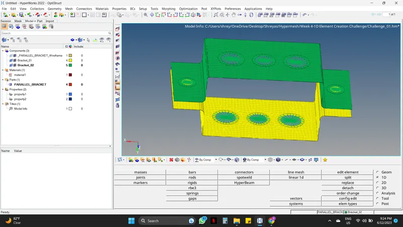
- The below fig shows the RBE2 connection at "b hollow section" where all the Translational DOF is Constrained with the RBE3 link (dof 1, 2, and 3 are checked)
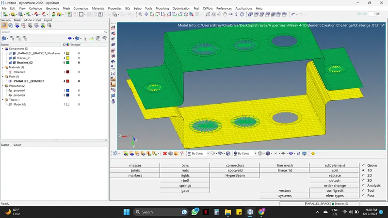
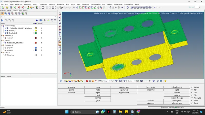
- The below fig shows the RBE2 connection at "c hollow section" where all the Translational DOF is Constrained with the RBE3 link (dof 1, 2, 4, and 5 are unchecked)
Step 09 : Creating the Properties for elements
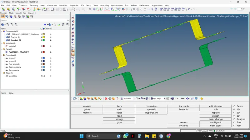
- Before creating the elements i.e. Rod, Beam, Bar, and Spring their properties must be created.
For creating properties follow the below steps :
Mouse right-click on the Tab area -----> Create -----> Property -----> Change the card Image from PSHELL to PROD (Hence this will be the property for the Rod)
NOTE :
Steps for creating the properties will be the same, only the card image will change according to the elements i.e. PROD, PBEAM, PBAR, PSHELL
Step 10 : Creating the elements
- Here for creating the elements i.e. Rod, Beam, and Bar the steps will be the same except for the dimensions.
- First, the elements must be created with proper dimensions in the Hyperbeam view, and after the creation, the elements must be assigned to their appropriate position.
Creation of elements in Hyper beam view :
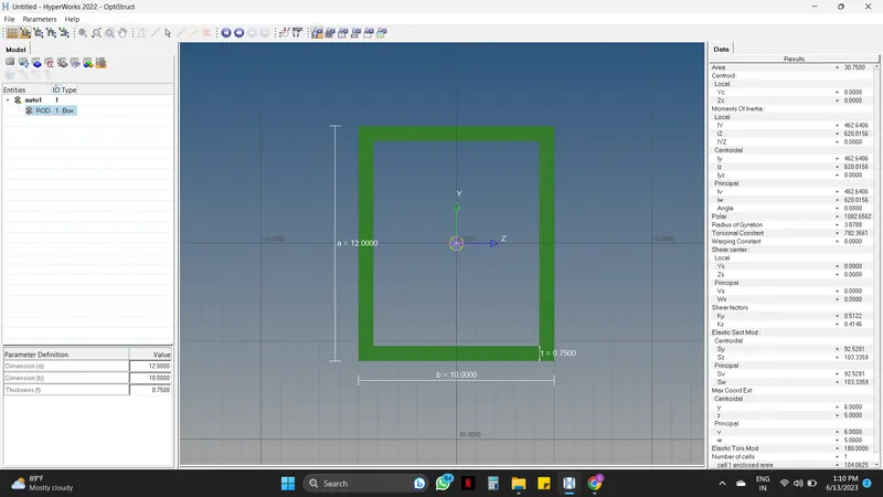
a. Rod element :
Cross-Section: BOX- Dimension a= 12 mm
dimension b=10 mm
Thickness t= 0.75 mm
Follow the below steps for creating the Rod element :
1D -----> Hyperbeam -----> Standard section ----> Select standard section library : HYPERBEAM & Standard section type : Thinwalled Box -----> Create -----> Give the dimensions -----> Rename it for better understanding.
- Hence the Rod element is created as per the given dimensions.
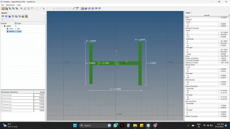
b. Beam element : All DOF should be constrained with RBE3 link
Cross-Section: I Section- Dimension a= 8 mm
Dimension b= 10 mm
Dimension c= 8.5 mm
Thickness t1= 0.75 mm
Thickness t2= .6 mm
Thickness t3= .6 mm
Follow the below steps for creating the Beam element :
- For creating the Beam element engineer can follow the above steps or can use a different approach as mentioned below which will help in the creation of the elements in one go.
Hyperbeam view -----> Mouse right-click on Tab area and select Create -----> Standard section ----> Hypermesh -----> Standard I section -----> Give the dimensions -----> Rename it for better understanding.
c. Bar element : Constrain only x and y DOFs With RBE3 link
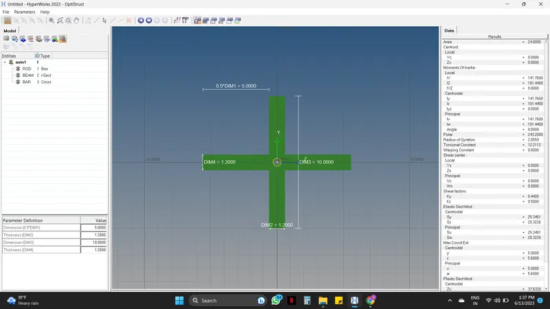
Cross-section: X section- Dimension DIM1= 5 mm
Thickness DIM2= 1.2 mm
Dimension DIM3= 10 mm
Thickness DIM4= 1.2mm
- The steps for creating the Bar element are similar to the above elements steps. Engineers can go with any approach.
Positioning the created Elements :
- For positioning the elements the very first step is to assign the Beam section of the element's property with their respective hyperbeam model. After assigning the Beam section the positioning can be done with the following steps.
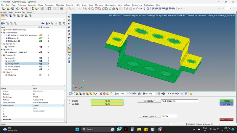
a. Rod element :
1D -----> Rods -----> Insert the property and the element type ----> Select the nodes where the rod must be created.
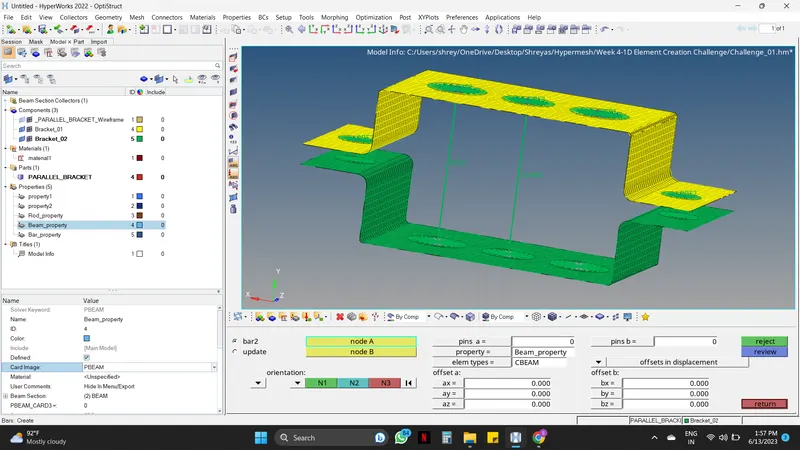
b. Beam element :
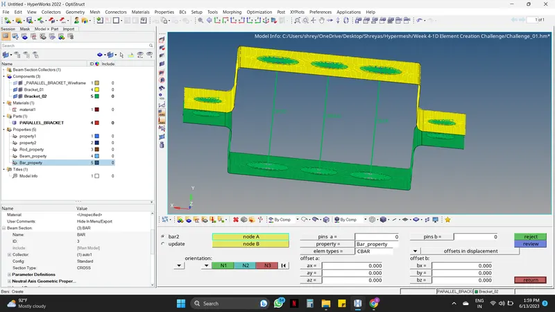
1D -----> Bars -----> Insert the property and the element type ----> Select the nodes where the Beam must be created -----> Select the cross-section.
c. Bar element :
1D -----> Bars -----> Insert the property and the element type ----> Select the nodes where the Bar must be created -----> Select the cross-section.
Step 11 : Applying the Masses
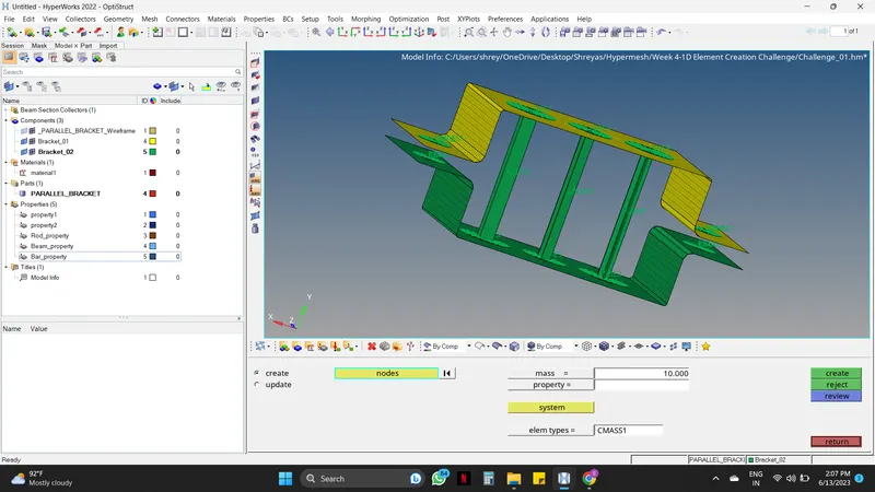
1D -----> Masses -----> Insert the mass value and the element type ----> Select the nodes where the Mass must be applied -----> Create.
Step 12 : Joining the components with Spring elements.
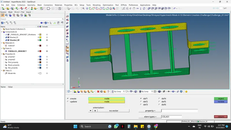
1D -----> Springs -----> Insert the element type : CELAS1 ----> Select the nodes where the Spring elements must be applied.
LEARNING OUTCOMES :
By doing this Project, the following aspects can be learned:
- Extraction of a mid surface, generation of Mesh, creation of the washer split on a component with assigning appropriate properties.
- Deploying the connection on different surfaces, and Creating solid elements as per any given dimensions.
- Familiarized and working with all the commands present on the Main menu such as Geometry, 1D, 2D, Tools, etc.
- Work on HYPERMESH Optistruct with a flow.
CONCLUSION :
- In this Project, all the given objectives were fulfilled using different commands and different approaches with ease.