Week 4-1D Element Creation Challenge
Aim
To mesh the given component with the size of 5 Units and to create 1D elements on the following component with given cross-section and DOF using Hypermesh.
Procedure
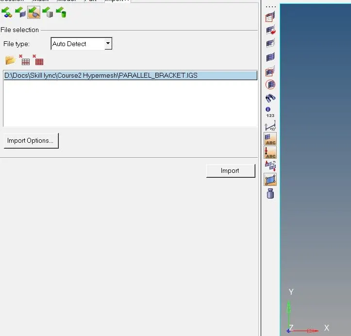
Imported the CAD geometry using the import geometry option on Hypermesh. As it supports the .igs file hence the challenge .iges file is successfully opened. Chose the optistruct profile to carry out the preprocessing.

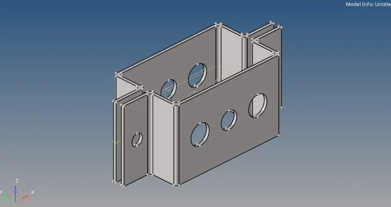
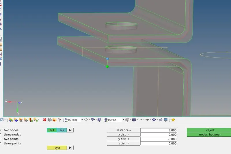
Measurements were taken for the sheet metal component (bracket)
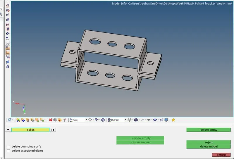
Before generating the midsurface at first performed the solid deletion on the component. Used delete option with solid selection then clicked on delete entity.
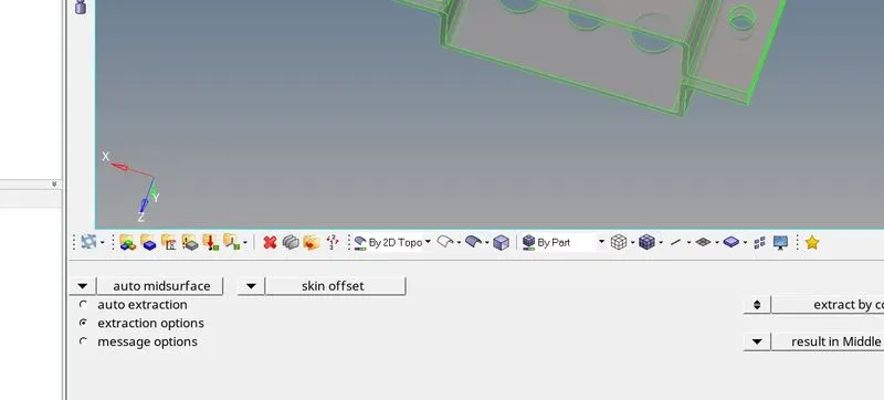
Now it's time for the mid surface to be generated as it reduces complexity during analysis by simplifying CAD and gives better simulation results in a shorter time. Used the Geometry>midsurface>automidsurface>extract option with extraction options as "skin offset" to generate the midsurface.
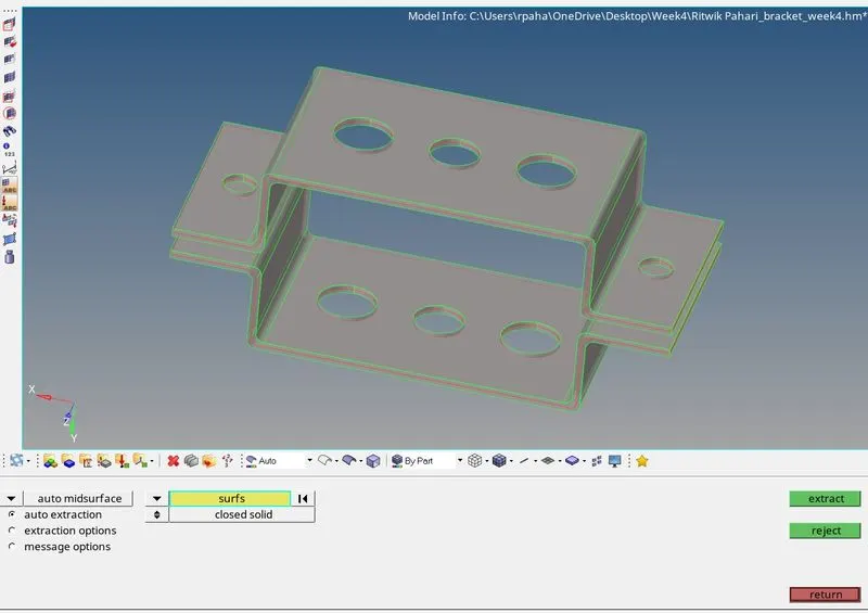
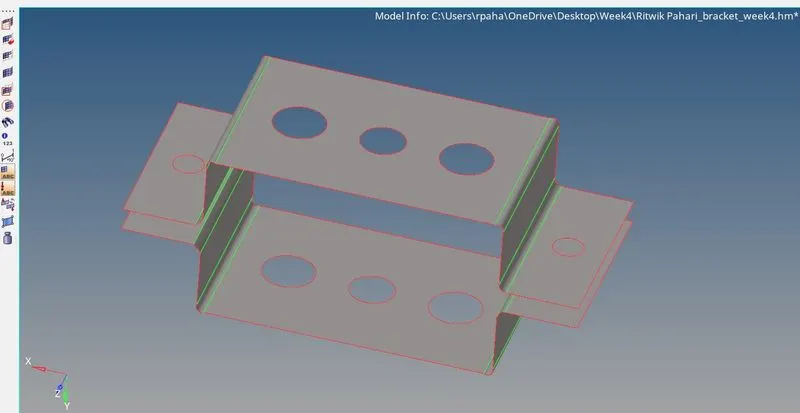
The midsurface which was generated:
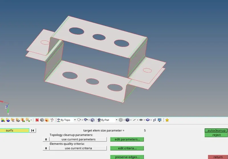
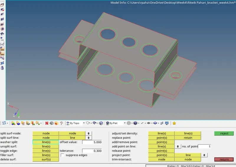
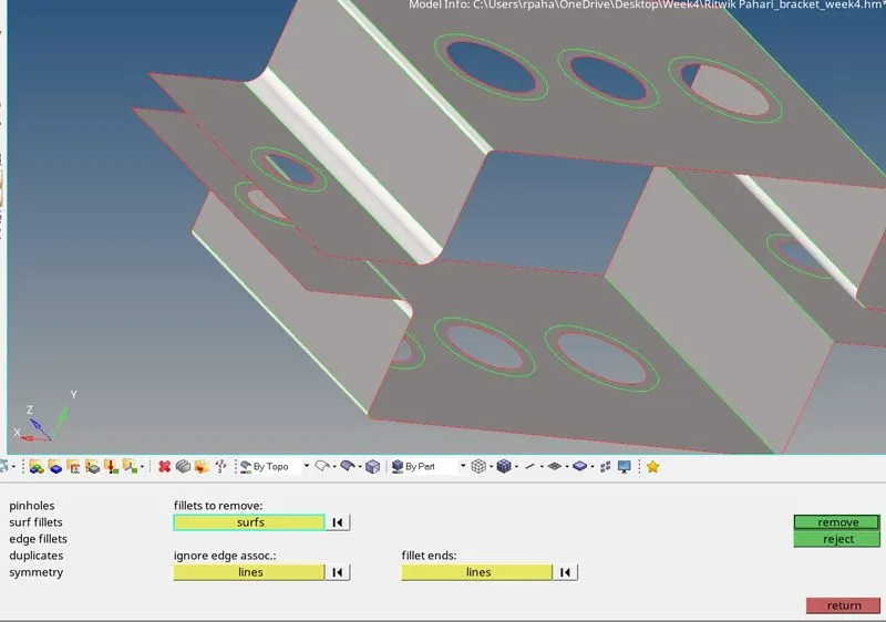
Geometry checkup for the whole component is performed using autocleanup by providing the target element size as 5. Sometimes this creates washer-splits on its own for the holes, but sometimes we have to do it manually. Used Quick edit>washer split with offset value as 5 to create the washer splits around the holes. Also defeatured the fillet regions for better mesh flow as the element size is slightly large and the fillets of the current component may not give a better mesh flow.(Geometry>Defeature>surface fillets>selected the lines making up the surface>find>remove)
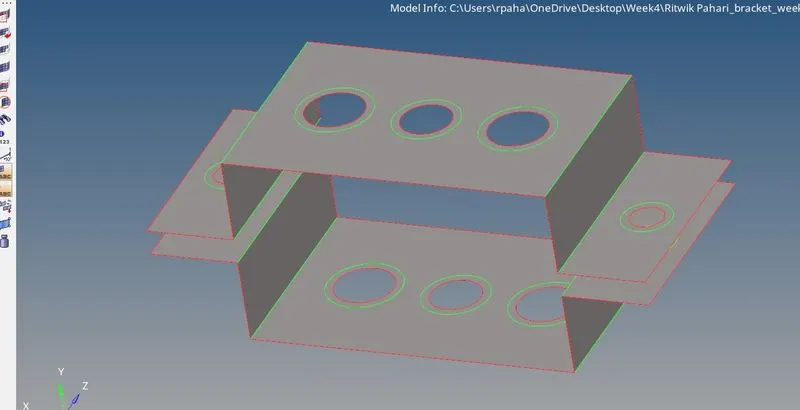
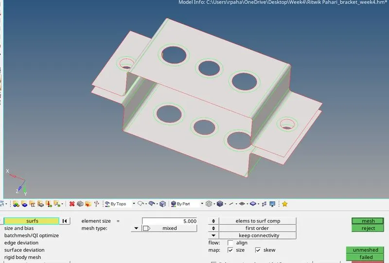
Now went to the 2D option and clicked on automesh. Given the element size as "5" units and selected the mesh type as "mixed", selected all the sufaces of the misurface using surfs>displayed and then meshed the component clicking on the mesh command.
Used the mesh and rebuild mesh command to achieve better mesh flow, used qualityIndex>cleanuptools> drag tria element to remove trias at the edges and the boundaries and also used this to combine opposite trias using combine option in the element edit option.
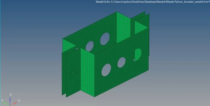
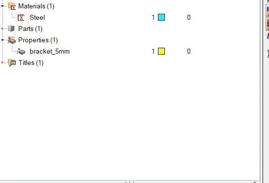
Here created a property and material for the midsurface component and provided the thickness as 5mm and assigned the material and property to the midsurface component so that the component and mesh can be viewed with 2D detailed representation.
After generating the mesh advanced towards the main objective of generating the 1-D elements. As provided in the question, carried out the generation of the RBE2 and RBE3 elements with the given DOF constraints in the given a, b, c, d, e, f areas.
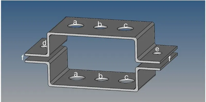
Created RBE2 link by going to 1d and then selected "rigids". Under create changed to calculate node and then selected nodes by path as node selection and selected the nodes at the periphery and around the washer limit and assigned the degrees of freedom as per requirement. For "a" translational DOF should be constrained with RBE2 link, for that selected degrees of freedom as, dof1, dof2 & dof3 only unticking the rotational DOFs. For "d" & "e" translational and rotational both degrees of freedom were constrained with RBE2 link, by selecting all the dofs.
Then created RBE3 elements at b region with all DOFs constrained and at c region with only x and y DOFs constrained.
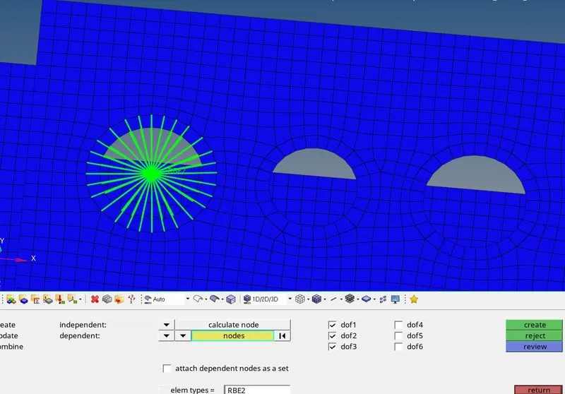
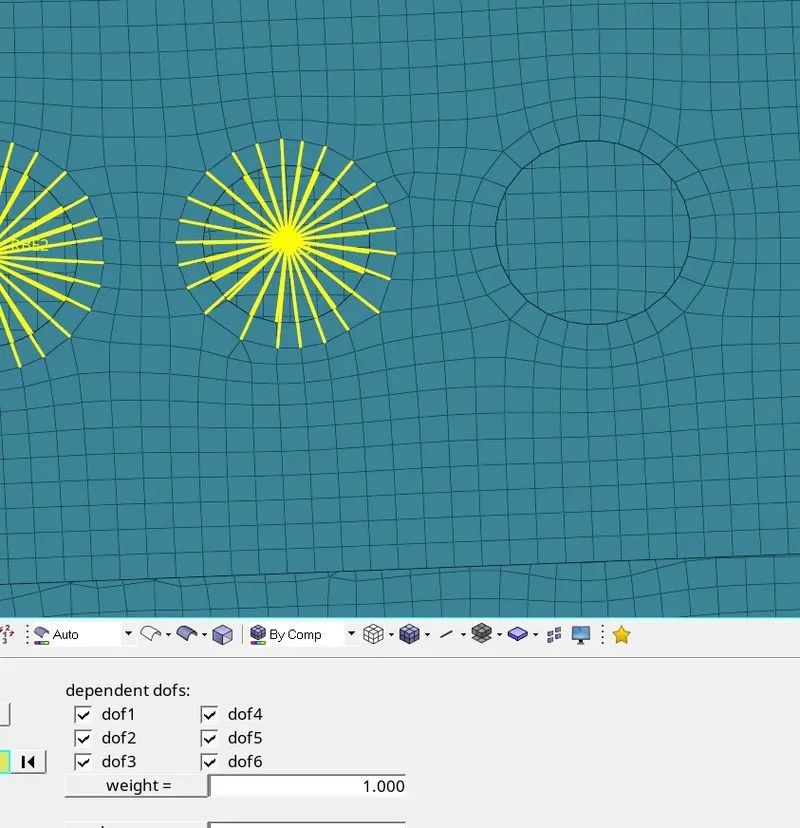
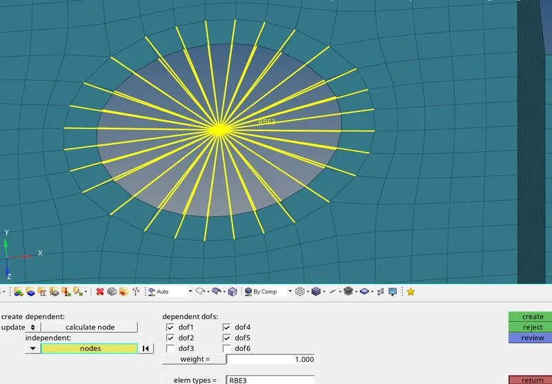
After creating all the RBE2 and RBE3 elements:
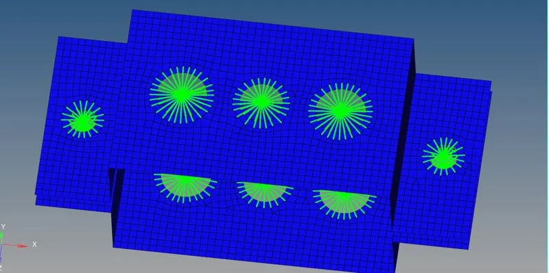
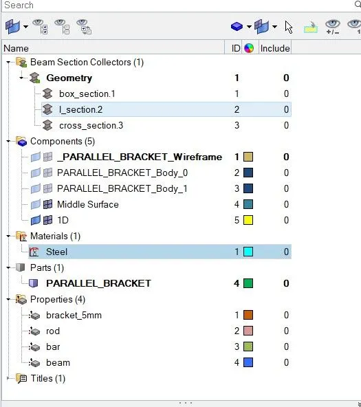
Now as per the question cross sections like box, I section and CROSS sections are to be made in order to provide the beam-section property to the rod, bar and beam. So to create these geometries used the 1D>Hyperbeam>Standard Section with thinwalled box turned on. A hyperbeam view was generated with a box cross section. Edited the box dimensions as per the question provided values :
Cross-Section: BOX- Dimension a= 12 mm
dimension b=10 mm
Thickness t= 0.75 mm
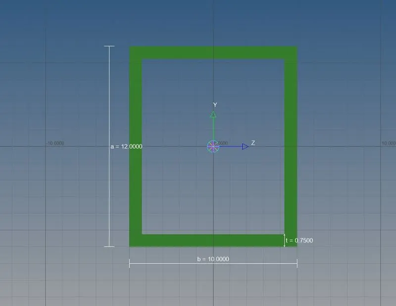
Then created the I section by right clicking on the hyperbeam menu and selected the Standard I section under hypermesh menu. Then edited the box dimensions as per the question provided values :
Cross-Section: I Section- Dimension a= 8 mm
Dimension b= 10 mm
Dimension c= 8.5 mm
Thickness t1= 0.75 mm
Thickness t2= .6 mm
Thickness t3= .6 mm
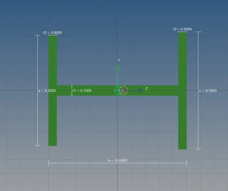
Then created the CROSS section by right clicking on the hyperbeam menu and selected the CROSS under optistruct menu. Then edited the box dimensions as per the question provided values :
Cross-section: X section- Dimension DIM1= 5 mm
Thickness DIM2= 1.2 mm
Dimension DIM3= 10 mm
Thickness DIM4= 1.2mm
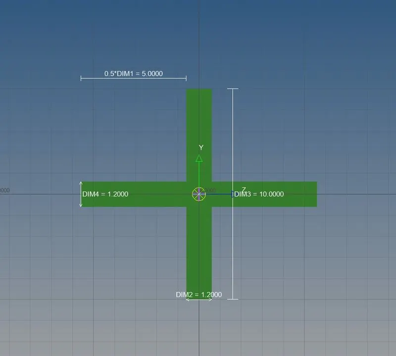
Now before creating the rod, bar and beam elements created the properties and materials for these entities. Then changed the card images as PROD, PBAR and PBEAM respectively, assigned the same material generated earlier and selected the beamsections as box, X section and I section respectively for rod, bar and beam in the property expanded tab.
Then generated the rod, bar and beam connections using the centre nodes of the RBE2 and RBE3 connections. In the 1D panel used the rod and bar options, selected the element type as CROD, CBAR and CBEAM respectively for rod, bar and beam, selected the nodes and created the rod, bar and beam elements. Also at "f" region selected corner nodes and generated spring elements using Springs option in the 1 D panel with dof1 turned on.
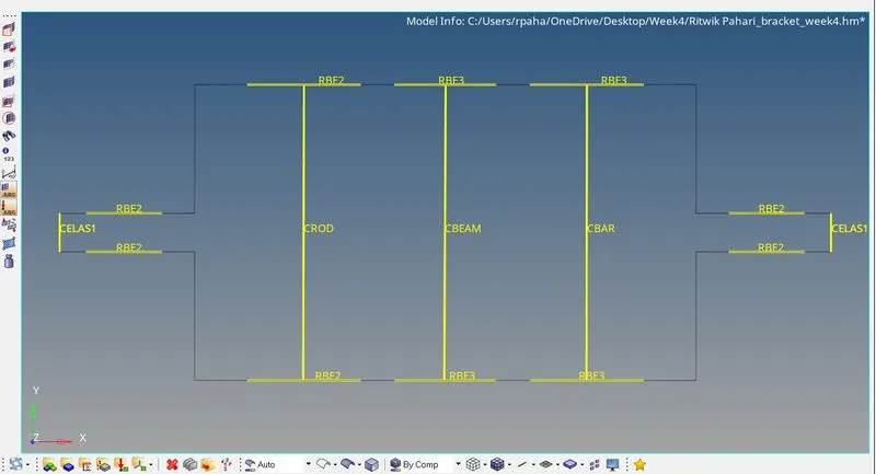
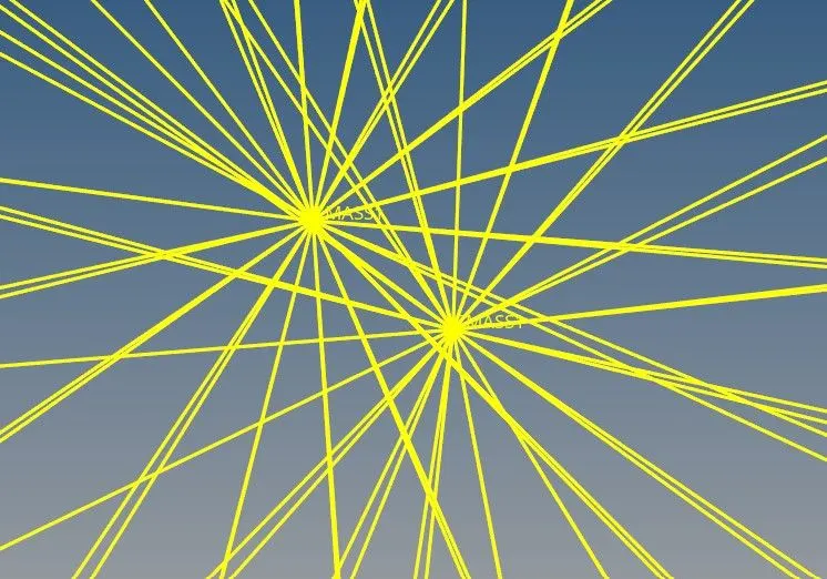
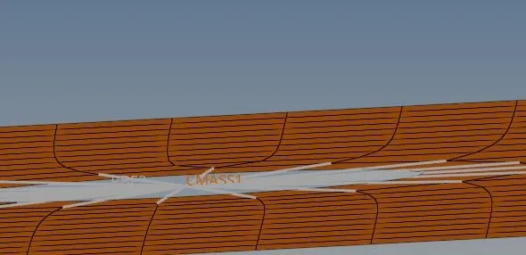
Then applied mass of magnitude 10 to the RBE2 links at "d" and "e". Used the masses option in the 1D panel, entered magnitude as 10 units, marked element type as CMASS1, assigned property same as the midsurface one, selected the node and provided mass.
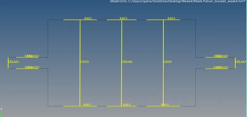
When viewed under property mode:
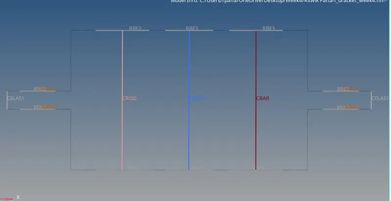
Viewed when "1D detailed element representation" option is turned on:
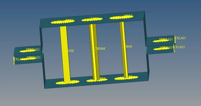
Zoomed in view:
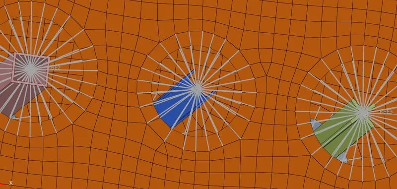
Viewed when "1D detailed element representation" and "2D detailed element representation" both options are turned on:
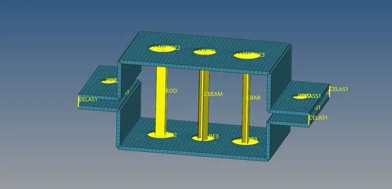
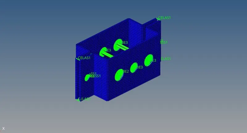
Learning Outcomes
At the end of this challenge I am more familiar with Hypermesh workflow, can perform cleanup, can generate mid surface, can perform defeaturing, can generate mesh and create 1-D elements.
Conclusion
Hence, the given component with the size of 5 Units is meshed and 1D elements on the following component with given cross-section and DOF are created using Hypermesh.