Week 4-1D Element Creation Challenge
OBJECTIVE:
- To perform mid surface extraction on the given cad model and mesh them using 2D elements.
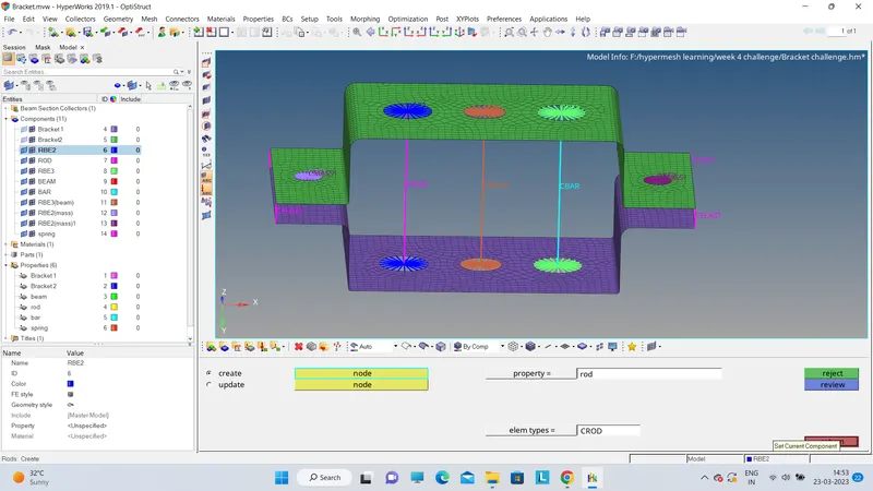
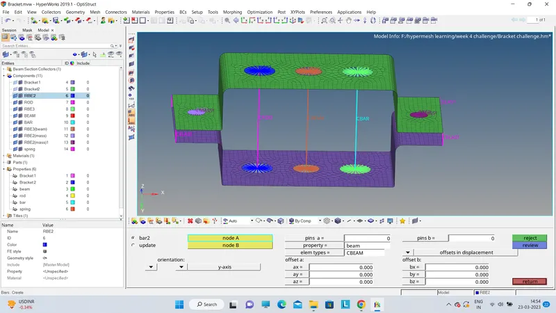
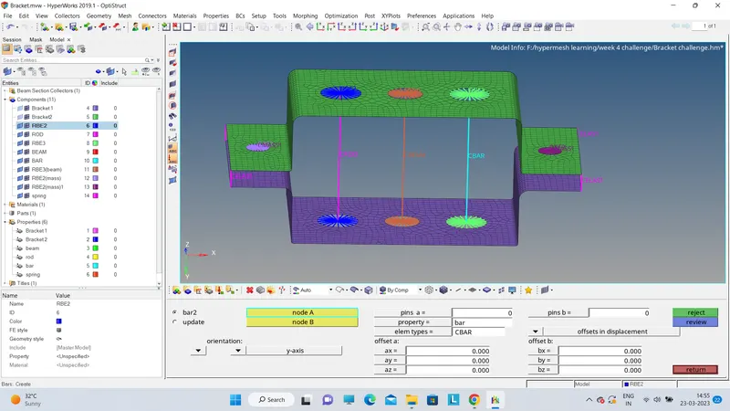
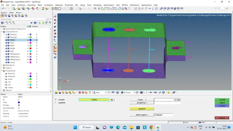
- Create rigid elements as per the instructions given , connect them using bar , rod and beam elements and assign cross section property to them.
CAD MODEL IMAGE:
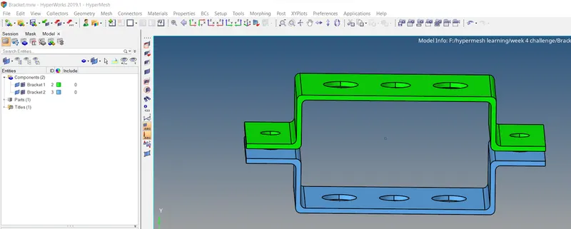
Here we can see two parts of bracket highlighted in different colours.
PROCEDURE:
1. Go to import > geometry > import the igs cad file.
2.Next part is the mid surface extraction. For this we have different option but to capture mid surface correctly use offset surface option.
Geometry > surface edit > offset > assign offset value of 3mm ( half of the thickness)
3. Mid surfaces are generated as given below.
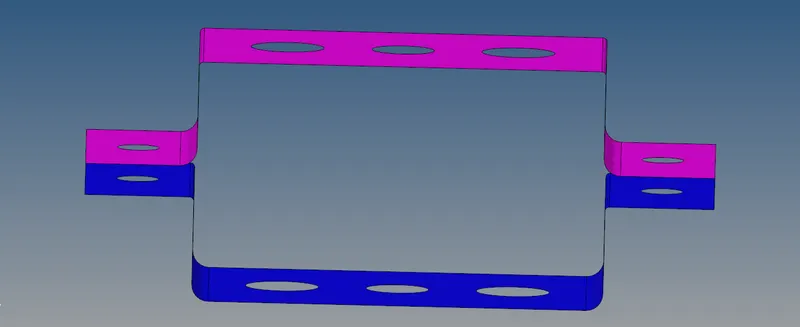
Rename these components as bracket 1 and bracket 2
4. Now delete the solid bodies from option delete > solids > delete entity
5. Create property for these brackets as PSHELL and assign material and thickness value of 6mm.
6. Assign each components these properties respectively.
7. Go to tools > washer split > assign value 5 as shown below
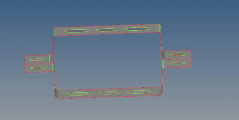
8. After this mesh the mid surface with value of 5mm and curvatures are captured accurately. The meshed photo is given below.
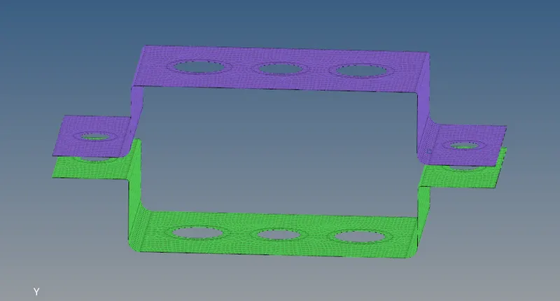
9. The quality of mesh is checked through 2D> quality index and check for duplicates and connectivity as shown below.
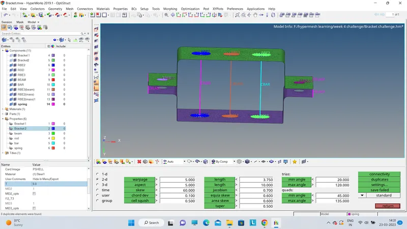
10. Now create RBE2 for hole 'a' as per the figure below by selecting nodes on the circumference of holes and constraining translational dof.
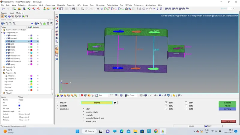
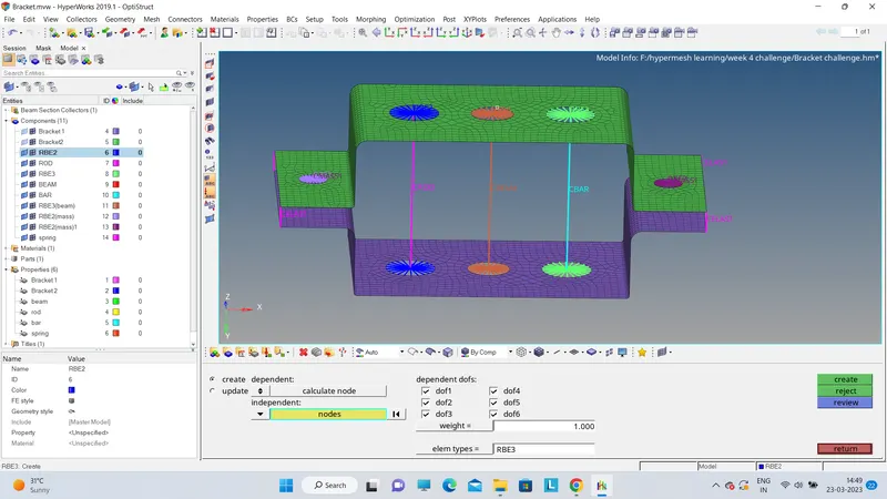
11. Create RBE 3 for hole 'b' with all dof constrained as shown below.
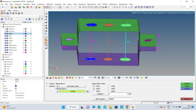
12. Create RBE 2 for hole 'c' with translational in x and y directions as shown below.
13. Similiarly create RBE 2 elements for hole d and e.
14. Create rod element for hole 'a' as shown below.
15. create beam element for hole 'b' as shown below.
16. Create bar element for hole 'c' as shown below.
17. create mass of unit 10 on hole d and e as shown below with element type C mass 1.
18. Finally create spring element with suitable stiffness to connect two brackets as shown below.

19. Now the final step is creating cross sections and assigning these to respective 1d elements. For that go to
hyperbeam > create standard section > Box section
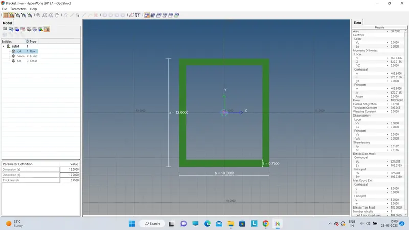
Similiarly create I section and Cross section with required properties.
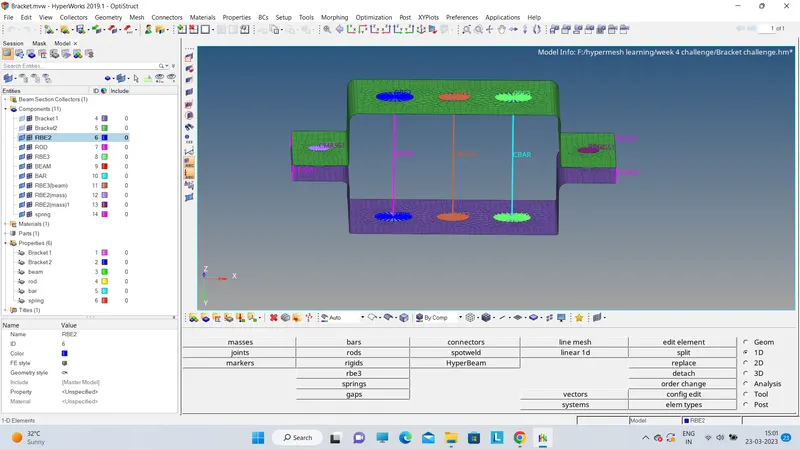
20. Create proprty card bar , rod , beam and assign these cross sections that are created and the property tabel look like below image.
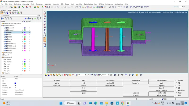
21. Assign all elements with these properties and click on detailed representation to view the complete model as below.
CONCLUSIONS
- Necessary commands to create mid surface , 1d elements etc were studied and applied over the model as shown above.
- Meshing was done satisfying the quality criteria also.