Week 4-1D Element Creation Challenge
Aim:- Mesh the given component and learn how to create 1D elements for different purposes.
Objective:- Mesh the Given component with the Size of 5 Units. Create 1D elements on the following component with given cross-section and DOF.
Given Data:-
a. Rod element:- Translational DOF should be Constrained with RBE2 link
Cross-Section: BOX- Dimension a= 12 mm
dimension b=10 mm
Thickness t= 0.75 mm
b. Beam element:- All DOF should be constrained with RBE3 link
Cross-Section: I Section- Dimension a= 8 mm
Dimension b= 10 mm
Dimension c= 8.5 mm
Thickness t1= 0.75 mm
Thickness t2= .6 mm
Thickness t3= .6 mm
c. Bar element:- Constrain only x and y DOFs With RBE3 link
Cross-section: X section- Dimension DIM1= 5 mm
Thickness DIM2= 1.2 mm
Dimension DIM3= 10 mm
Thickness DIM4= 1.2mm
d. & e. Apply the mass of magnitude 10 with the RBE2 link
f. Join the two components with Spring elements
Figure 1:- Given
Procedure:-
1. Import Model: First import the given model which is in IGS file type.
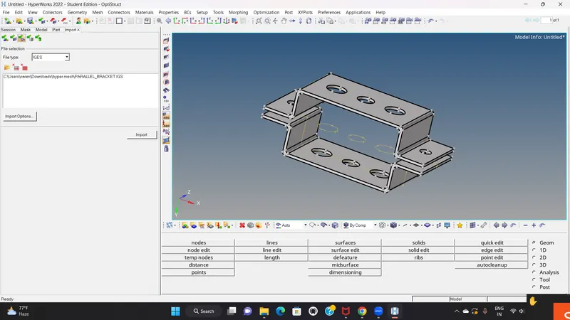
Figure 2:-Import Model
2. Mid Surface:
* Extract the mid surface for the model by using midsurface option in geometry panel. for both brackets we have to extract the midsurface separately. we use automidsurface option for creating mid surface where we use extraction option as Skin offset for creating mid surface.
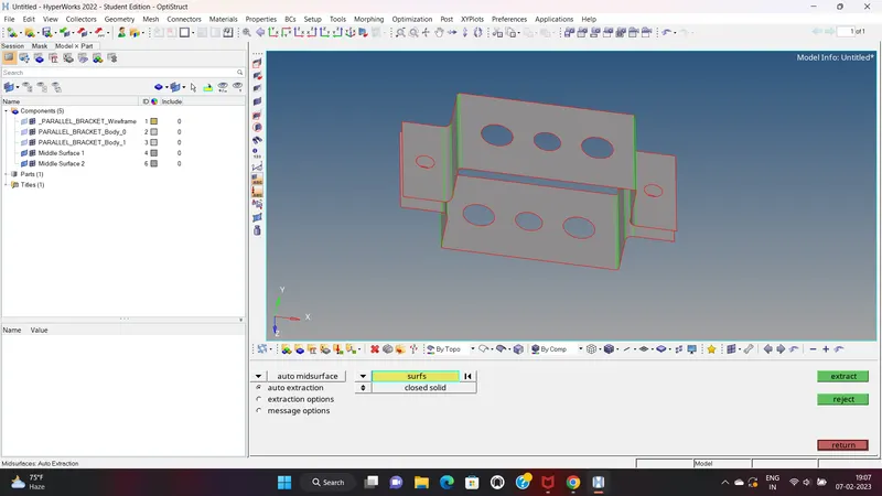
Figure 3:-Mid Surface
3. Meshing:
WAsher split:
* Washer split is used to capture the mesh near the holes properly.
* The offset value for washer split is 5 units.
* Then we do autocleanup of the geometry which is the primary procedure of meshing. ( geom-autocleanup)
* After the autocleanup the go to 2D and click on automesh and done mseh by size and bias mesh type with the mixed element and element size is 5 units and mesh the component. (2D-automesh)
* Around the circles increase the density and done meshing process.
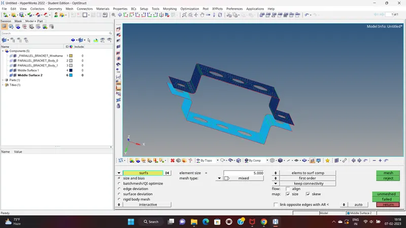
Figure 4:- Meshed model
4. 1D Elements:
* 1D elements used in this project are,
CROD
CBEAM
CBAR
REB2
REB3
* First we create the REB2 and REB3 link on the different hole as specified in the objective.
* For creating REB2 link we have to select 1D panel and then click on the rigids. then create the REB2 link with different DOF ( degree of freedom).
* For creating REB3 link we have to select 1D panel and then click on the reb3 and create reb3 link with appropriate DOF.
* To given the required shape (cross-section) to the bar, rod, beam we use Hyperbeam section of hypermesh.
For Rod element:-
BOX
Dimension a= 12 mm
dimension b=10 mm
Thickness t= 0.75 mm
* to create the Box cross section go to 1D - Hypermesh - create - standard section - hypermesh - thin walled box.
* the given cross section is created and enter the given dimentions data as shown in figure.
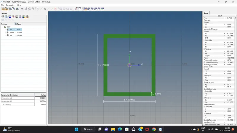
Figure 5:- Rod (cross section)
For Beam element:-
Cross-Section: I Section
Dimension a= 8 mm
Dimension b= 10 mm
Dimension c= 8.5 mm
Thickness t1= 0.75 mm
Thickness t2= .6 mm
Thickness t3= .6 mm
* to create the I cross section go to 1D - Hypermesh - create - standard section - hypermesh - I -section
* the given cross section is created and enter the given dimentions data as shown in figure
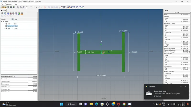
Figure 6:- Beam (cross section)
For Bar element:-
Cross-section: X section
Dimension DIM1= 5 mm
Thickness DIM2= 1.2 mm
Dimension DIM3= 10 mm
Thickness DIM4= 1.2mm
* to create the X cross section go to 1D - Hypermesh - create - standard section - Optistruct - Cross.
* the given cross section is created and enter the given dimentions data as shown in figure.
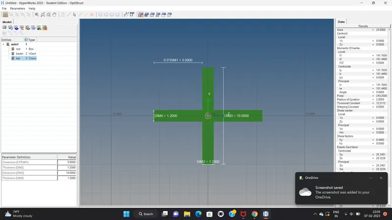
Figure 7:- Bar (cross section)
Hence, the cross section has been created for bar ,rod and beam element as per given data. Now these cross section should be assigned to the perticular property.
5. Assign property;-
* After creating cross section we have to create the properties for the different elements.
* Then we have to assign the property to the perticular components and materials.
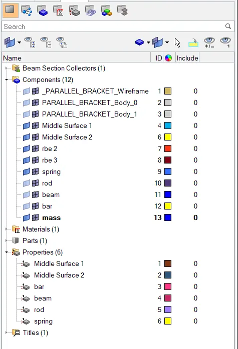
a. Creation of Rod element-
* First we creat the REB2 cluster in both hole (a) in bracket surface.
* Then give appropriate DOF as per given insturction.
* Creat CROD element by connecting hole (a).
* And give BOX cross section by using Hyperbeam section.
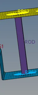
Fig 7:- Creation of rod element
b. Creation of Beam element-
* First we creat the REB3 cluster in both hole (b) in bracket surface.
* Then give appropriate DOF as per given insturction.
* Creat CBEAM element by connecting hole (b).
* And give I cross section by using Hyperbeam section.
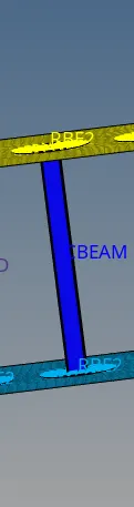
Fig 8:- Creation of beam element
c. Creation of Bar element-
* First we creat the REB3 cluster in both hole (c) in bracket surface.
* Then give appropriate DOF as per given insturction.
* Creat CBAR element by connecting hole (b).
* And give X cross section by using Hyperbeam section.
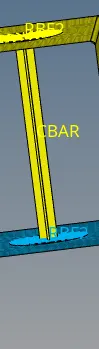
Fig 9:- Creation of bar element
d. & e. Apply the mass of magnitude 10 with the RBE2 link:-
* Created REB2 cluster for hole (d and e ) as per input data.
* And then applied a mass of a magnitude 10.
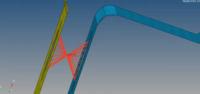
Fig 10:- mass on d and e hole
f. Join the two components with Spring elements :-
* For joining two components we use spring element , and use of rbe2 rigid element*
* First we create a roh of rbe2 element in the end edge of upper component and as well as bottom and then fix the spring element between them.
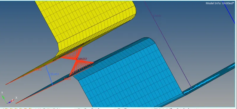
Fig 11:-join of 2 component with spring
Conclusion:- Here we mesh the given component and create the 1-D elements as per given instruction, and we learn how to create 1D element and how to use them into a model.
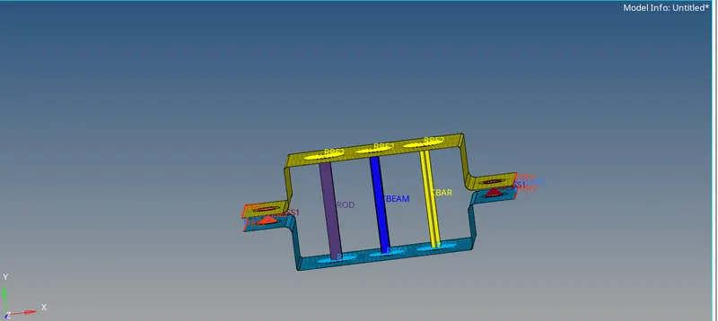
Fig 12:- Complete meshed bracket model with 1D elements