Week 4-1D Element Creation Challenge using HYPERMESH
AIM:
To Mesh the Given component with the Size of 5 Units & to Create 1D elements on the following component with given cross-section and DOF.
GIVEN DATA:
a. Rod element:- Translational DOF should be Constrained with RBE2 link
Cross-Section: BOX- Dimension a= 12 mm
dimension b=10 mm
Thickness t= 0.75 mm
b. Beam element:- All DOF should be constrained with RBE3 link
Cross-Section: I Section- Dimension a= 8 mm
Dimension b= 10 mm
Dimension c= 8.5 mm
Thickness t1= 0.75 mm
Thickness t2= .6 mm
Thickness t3= .6 mm
c. Bar element:- Constrain only x and y DOFs With RBE3 link
Cross-section: X section- Dimension DIM1= 5 mm
Thickness DIM2= 1.2 mm
Dimension DIM3= 10 mm
Thickness DIM4= 1.2mm
d. & e. Apply the mass of magnitude 10 with the RBE2 link
f. Join the two components with Spring elements
Figure 1. Given data
THEORY:
PROJECT METHODOLOGY:
1. MID SURFACE:
- Auto mid surface has been used to extract the midsurface for this simple bracket.
- Components has been created and assigned to the particular mid surfaces.
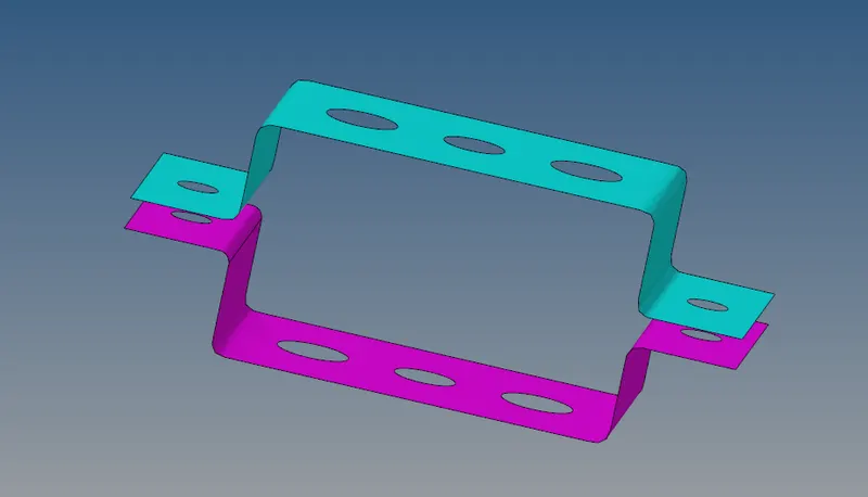
Figure 2. Mid surface
2. ASSIGN MATERIAL:
- Create material.
- Here I have created a material and assigned to steel.
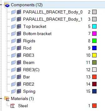
Figure 3. Component & materials assigned
3. ASSIGN PROPERTY:
- Create property
- Enter Thickness value & element type.
- Also assign this created property to the particular component & material.
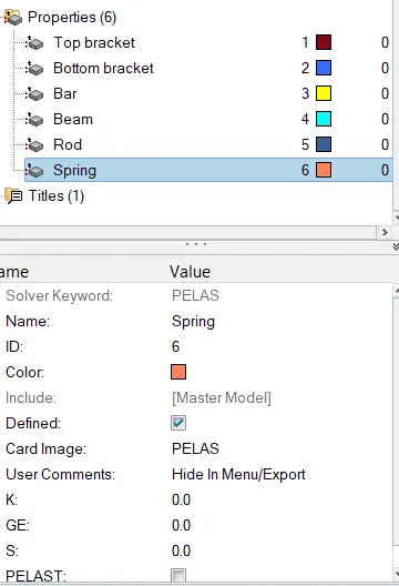
Figure 4. Property assigned
4. WASHER SPLIT:
- Washer spilt is used to capture the mesh near the holes properly.
- The washer split offset value is given to 5 units in this project.
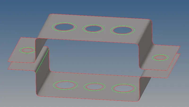
Figure 5. Washer split
5. 2D MESH:
- For this project auto mesh is been performed for the element target length of 5 units.
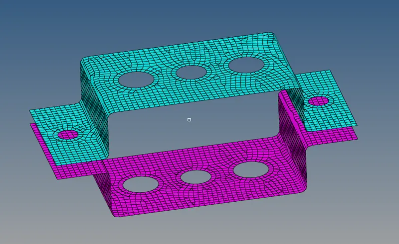
Figure 6. Shell mesh
6. 1D ELEMENTS:
- Some 1D elements used in this projects are,
- PBAR
- PROD
- PBEAM
- RBE2
- RBE3
- As per the given details I have deployed the 1D elements.
- To deploy bar, rod, beam elements hyperbeam has been used.
- Where hyperbeam is used to create a cross sections.
HYPERBEAM:
From the given data a. rod element, b. beam element, c. bar element we will be creating a cross sections using hyper beam.
a. Rod element - (cross section - box):
- The given cross section details for rod elements are,
-
Cross-Section: BOX
-
Dimension a= 12 mm, b=10 mm
-
Thickness t= 0.75 mm
-
- To create this cross section Go to --> 1D --> Hyperbeam --> Create --> standard section ---> Hypermesh --> Thin walled box.
- The standard cross section shape will be created and enter the given dimensions data as shown in the below figure.
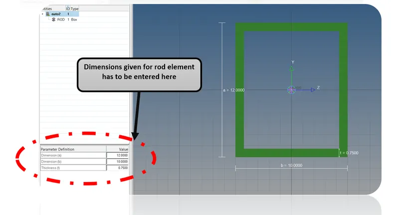
Figure 7. Box - cross section (Rod) - HYPER BEAM
b. BEAM ELEMENT - (I-Section):
- The given cross section details for beam elements are,
- Cross-Section: I Section
- Dimension: a= 8 mm, b= 10 mm, c= 8.5 mm
- Thickness : t1= 0.75 mm, t2= .6 m, t3= .6 mm
- To create this cross section Go to --> 1D --> Hyperbeam --> Create --> standard section ---> Hypermesh --> I - section
- The standard cross section shape will be created and enter the given dimensions data as shown in the below figure.
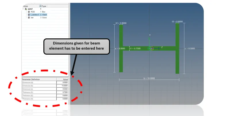
Figure 8. I-Section (Beam) - HYPER BEAM
c. BAR ELEMENT (X -SECTION):
- The given cross section details for beam elements are,
- Cross-section: X section
- Dimension DIM1= 5 mm
- Thickness DIM2= 1.2 mm
- Dimension DIM3= 10 mm
- Thickness DIM4= 1.2mm
- To create this cross section Go to --> 1D --> Hyperbeam --> Create --> standard section ---> Optistruct --> CROSS
- The standard cross section shape will be created and enter the given dimensions data as shown in the below figure.
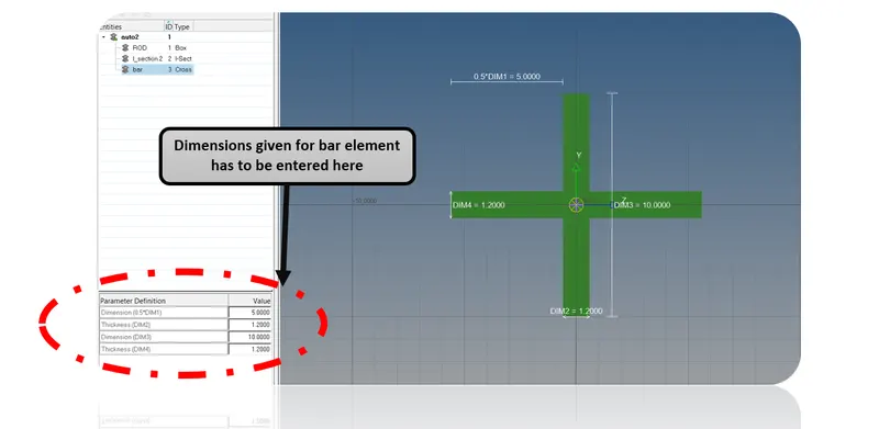
Figure 9. X-SECTION (Bar) - HYPERBEAM
Hence, the cross section has been created for bar, rod, beam element as per given data. Now these cross sections should be assigned to the particular property.
APPROACH:
a. Approach for Rod element:
- Created RBE2 cluster element for hole (a) by constraining translational as per input data.
- Created CROD element by connecting hole (a).
- CROD - Thin walled cross section as per input.
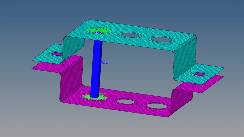
Figure 10. Approach a.
b. Approach for beam element:
- Created RBE3 cluster element for hole (b) by constraining all dof as per input data.
- Created CBEAM element by connecting hole (b).
- CBeam - I-cross section as per input.
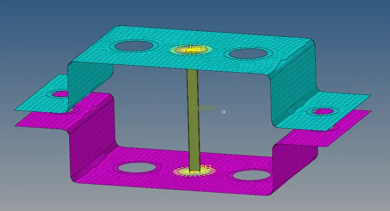
Figure 11. Approach b.
c. Approach for BAR element:
- Created RBE3 cluster element for hole (c) by constraining only X & Y dof as per input data.
- Created CBAR element by connecting hole (b).
- CBAR - X -section as per input.
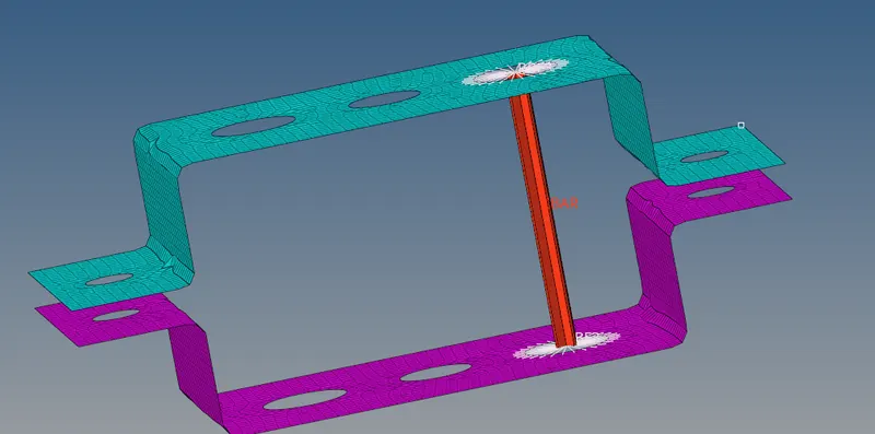
Figure 12. Approach c.
d. & e. Apply the mass of magnitude 10 with the RBE2 link:
- Created RBE2 cluster element for hole (d & e) as per input data.
- Applied a mass of magnitude 10.
- Cmass
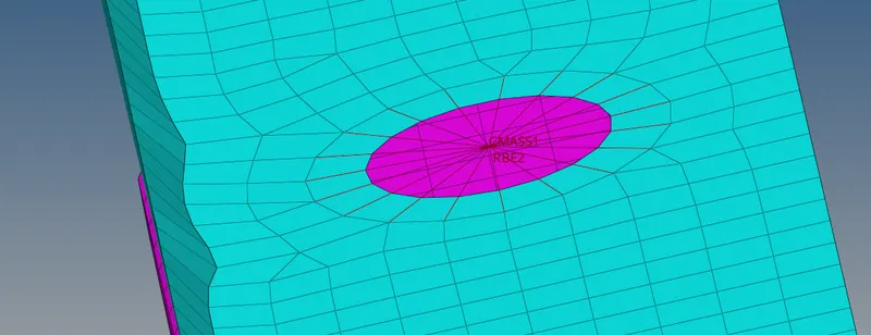
Figure 13. Approach d & e
f. Join the two components with Spring elements
- Spring elements are created at the four corners of the brackets to join the component.
- CElas
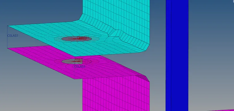
Figure 14. Approach f
Finally, Select 1D detailed element representation to view the cross section of bar,rod, beam element & Select 2D detailed element representation to view the thickness of the mid surface.
CONCLUSION:
The mesh & creation of 1D element has been successfully achieved as per the given inputs.
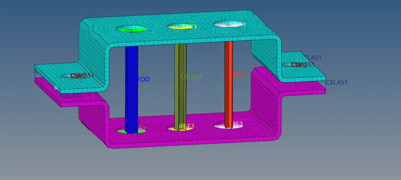
Figure 15. Final view
LEARNING OUTCOMES:
From this challenge, I can able create a 1D element as per the given inputs.