Week 4-1D Element Creation Challenge
Challenge 3
Aim – Creating 1D element.
Google Drive Link- https://drive.google.com/file/d/1SaqZoDXSJvM8wYM6BpkoSDcy9nzLs4y1/view?usp=share_link
Procedure-
Step 1 – Import the CAD model. Measured the thickness of bracket from geometry-dimensioning-selected the two nodes.
Step 2 -Extracted the mid surface of the bracket from Geometry- Mid surface – auto mid surface -Selected the body -Extract.
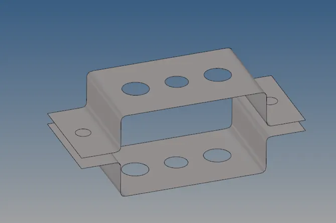
Fig 1- Mid surface of component.
Step 3 – created the material and property Card assigned the thickness to 5 units. From Model Menu- RMB- Create -new- material card. Same method for property card . assigned the material and the property card to the mid surface.
Step 4- Added the zone cut of 4 units near the holes, From Geometry- Quick edit- washer split.
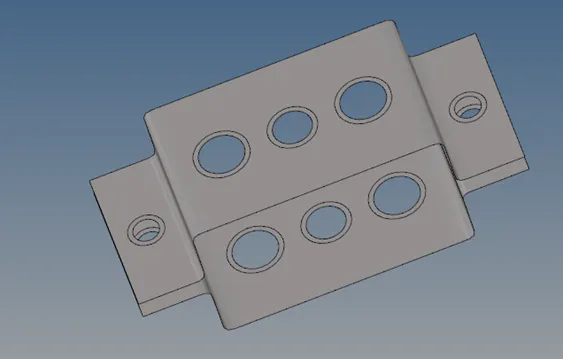
Fig 2 – Washer Split.
Step 5- Meshing the mid surface from 2D- auto meshing- element size as 5- element type – mixed.
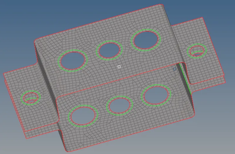
Fig 2 – meshing
Step 6 –
- Created cluster RBE 2 elements for Rod Element location, from 1 D –Rigids - Calculate nodes-multi nodes - selected the nodes By Path -MMB. Same process other hole.
- Created RBE 3 element for Beam element hole from 1 D – RBE 3-selected the nodes-MMB
- Same Procedure for Bar element holes except constrained only X and Y DOF .
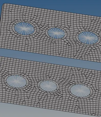
Fig 3 – RBE3 and RBE2 Elements.
Step 7 – Created the cross section for the Rod, Bar and beam element from 1D- Hyper beam-create- standard section - Box – define the dimension. Similar process for Cross and I-section.
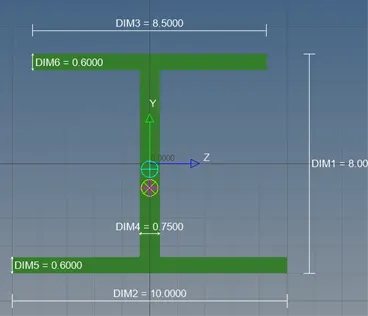
Fig 4 – I section
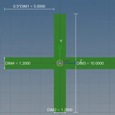
Fig 5- X (Cross) section
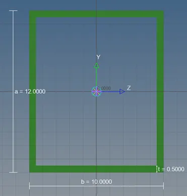
Fig 6- Box section
Step 8 - Created the Property Car for BAR, Beam and ROD, assigned the cross section, material and Card image to PBAR,PBEAM and PROD as per the question.
Step 9 –Joined the master nodes with BAR from, 1D-Bar-Selected the two master nodes- Property to Bar-Element type to Cbar-orientation – 2 parallel nodes near hole.
Step 10- Joined the master nodes with Beam from, 1D-BAR-Selected the two master nodes- Property to Bar-Element type to C Beam-orientation – 2 parallel nodes near hole-MMB.
Step 11 - Joined the master nodes with ROD from, 1D-ROD-Selected the two master nodes- Property to Bar-Element type to CROD-MMB.
Step 12- Applied mass from, 1D-masses-10 units- selected the nodes-Element type – ConM2-MMB
Step 13- Added the spring elements from 1D – Springs – Selected the Parallel nodes-MMB.
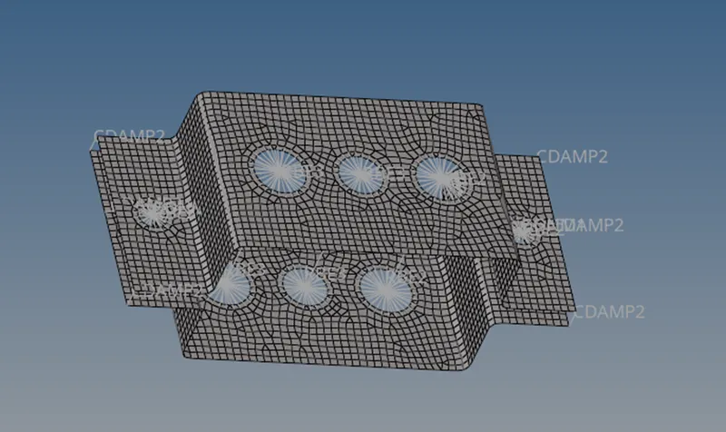
Fig 7 – Model after applying all connections and elements.
Step 14 – Correct Representation of all elements by switching on the 1 D detailed Element representation and 2 D detailed element representation.
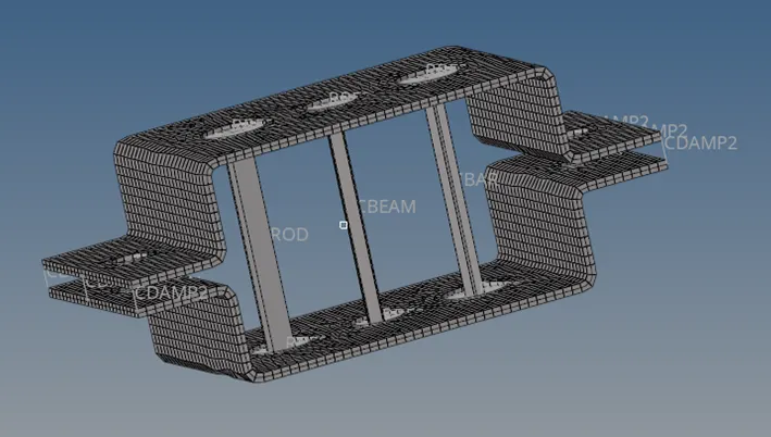
Fig 8 -Detailed representation.
Conclusion
- We learned about the different types of 1D element and application of the same.
- Learned about the hyperbeam option of hypermesh.
- Basics of meshing and washer split.