Week 4-1D Element Creation Challenge
Step 1: Open the Hypermesh> optistruct.
Step 2: Click on import the model select the file location of the given downloaded file then click import.
Step 3: The model of the parallel brackets is seen as shown. Now create a mid surface to each bracket with different names say brac1 and brac2. Create a material for the brackets here let's take Mat 1 element and name the material. Create properties for each of them separately as property1 and property2.
Step 4: Now define the material in properties 1 and 2 with the material name. Also, define the property in the created components. The model can be deleted as we have extracted the midsurface of it.
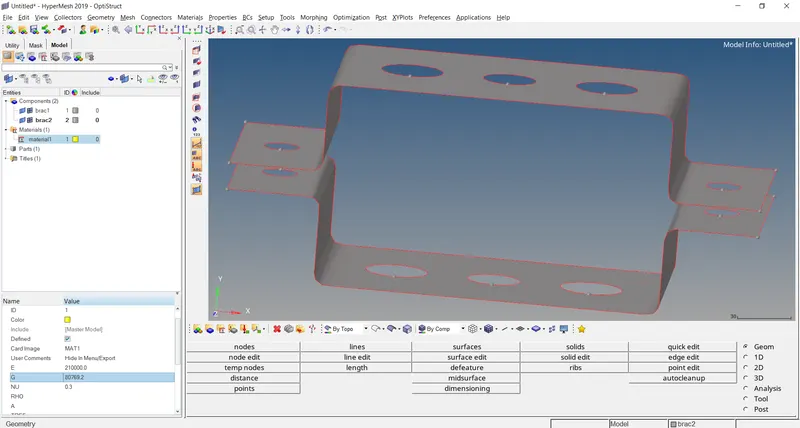
Step 5: As we can see there are circular holes in the geometry. To get a better mesh we can add a circle around it. Go to Geometry > quick edit > washer split. Change the offset value to a higher value and select the circle around which we are creating another circle.
Step 6: Now in 2d select automesh option with element size as given. First, select the circular surfaces and mesh them. For a better mesh, you can change the number of elements being made. Then select all the other surfaces and click mesh.
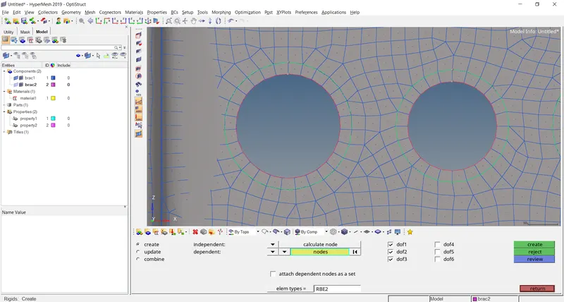
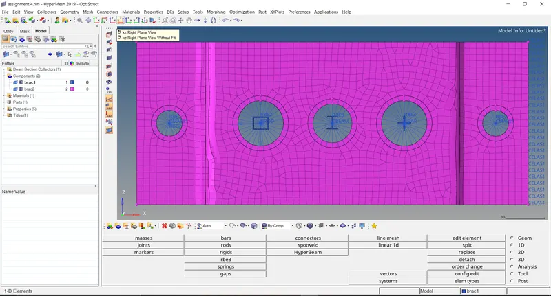
Step 7: Now go to 1D > hyperbeam > standard > thin-walled box > create. Here we get a tab where the values are given are placed. This can be done for the other just by right-clicking Create> (Type) in our case I section and cross.
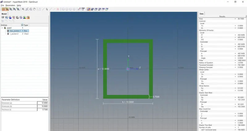
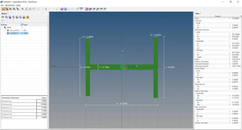
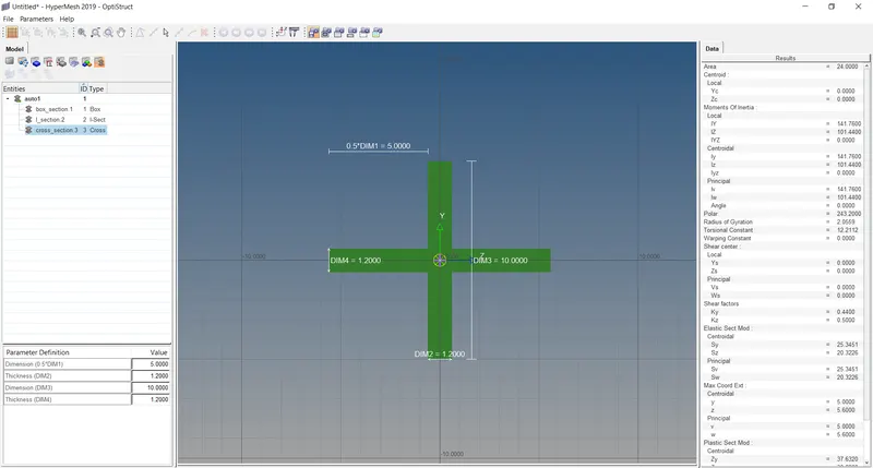
Step 8: After finishing click on the model at the top to go back to our model. At A we need a rod element with an RBE2 link. First create an RBE2 link i.e. rigid > multiple nodes > calculate nodes > Dof 1,2,3. Now select the nodes of a and click create.
Step 9: Similarly for RBE3 elements according to the DOF asked. After completion of RBE2 & RBE3 elements, we have to assign them to the element asked.
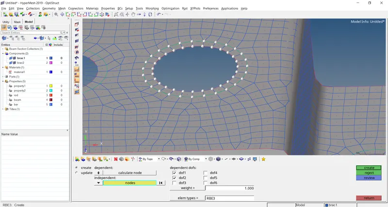
Step 10: To create a rod element 1D > Rods > elem types > CROD > select the points A in both Brackets > create.
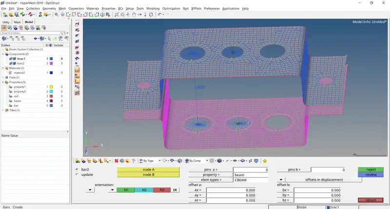
Step 11: Beam elements 1D > Bars > elem types > CBEAM > select the RBE3 nodes and the circumference > create
Step 12: Bar elements 1D > Bars > elem types > CBAR > select the RBE3 nodes and the circumference > create.
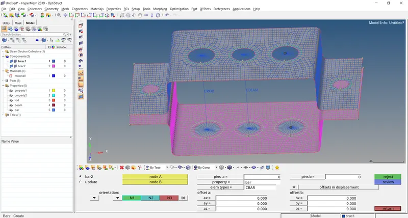
Step 13: For masses select the node and type the mass, select the property as 1 for brac1 and 2 for brac2 as we have assigned it to them. As we can see we have not assigned the property for the beam, bar, and rod lets make these properties.
Step 14: For rods select PROD and the beam section as a box which we have already made, similarly for beam>PBEAM for bar>PBAR.
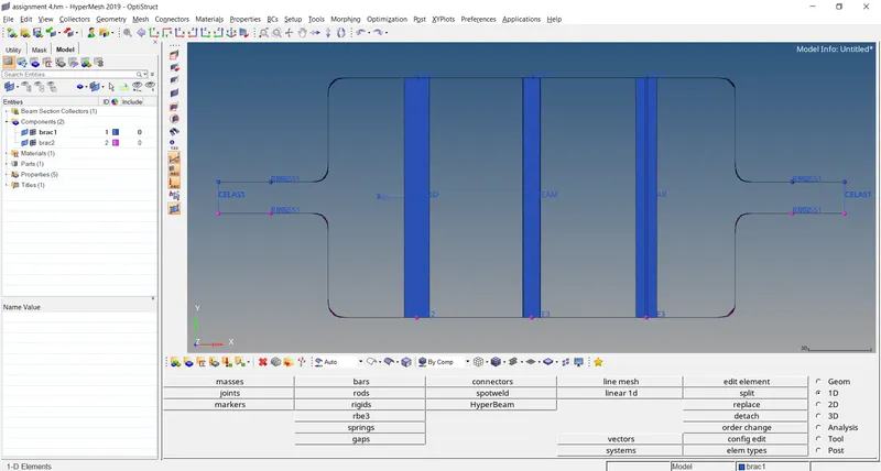
Step 15: Now go to rods and update the property also for beam and bar. From the top view, it looks like this.
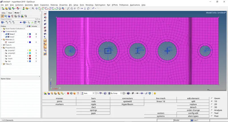
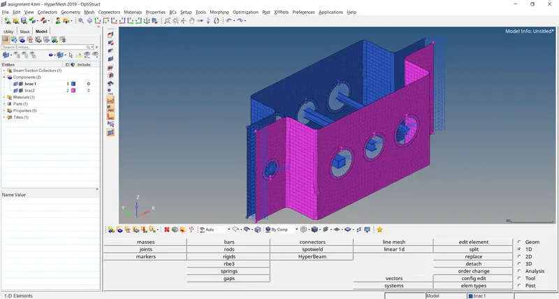
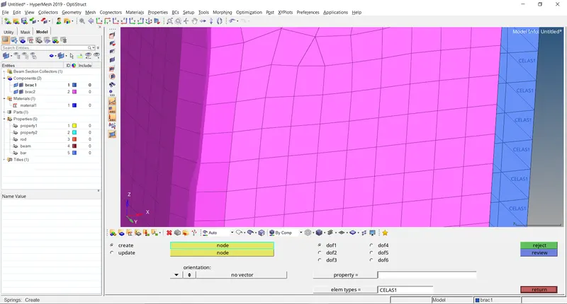
Step 16: To join the two components at the edge using springs go to spring > select the two nodes and a spring element is made do it for all the nodes in the edge i.e. at F as asked.
The result is as shown: