Week 4-1D Element Creation Challenge
#3 - Week 4 /1D Element Creation Challenge. ->
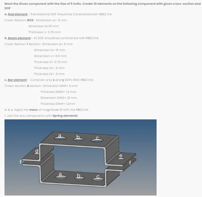
AIM: To study and create 1D element on the given component.
OBJECTIVE:
- To mesh the model with the given element size of 5units.
- To create 1D elements on the component with the given cross-section and degree of freedom(dof).
INTRODUCTION:
1D elements are used for modeling line-type members such as columns, piers, beams or poles. 2D elements are commonly used for plate-type members such as walls, slabs, shells, bridge abutments, tanks, domes. 3D elements are used for structure with complex geometry which cannot be simplified for analysis.
While working with 1D elements we come across the following element types:
- CROD
- CBAR
- CBEAM
-> CROD:
- CROD elements support (allow) tension and compression only. Also, in certain software’s used for rotational as well but also limited.
- The nodes of a CROD element only have translation degrees of freedom (still this element has a torsional stiffness).
-> CBAR:
- CBARS elements support (allow) tension, compression and bending as well.
- A CBAR element is a kind of simplified CBEAM element and should be used whenever the cross-section of the structure and its properties is constant and symmetrical.
- The CBAR element requires that its shear centre and the neutral axis coincide. Due to this requirement CBAR elements are not useful for modelling structures that may warp, such as open channel-sections.
-> CBEAM:
- CBEAMS elements support (allow) tension, compression and bending as well.
- CBEAM elements are used to model more “complicated” geometries with varying cross-sections.
- In CBEAM elements the neutral axis and shear centre are non-coincident.
Apart from above 1D Elements, there are different types of 1D Elements used to connect the nodes, which are called Rigid Links.
- RBE2
- RBE3
-> RBE2:
- RBE2/Rigids are 1D elements has infinite stiffness and the nodes will not move at all.
- In RBE2 links the applied load will be distributed equally irrespective of their position and distance from the node to each and every element.
-> RBE3:
- RBE3 elements, on the other hand, serve to distribute loads without inducing unwanted stiffness. It is not an element to be used to model a connection, but rather an element to induce a motion in a node as a function of the weighted average of other nodes.
- RBE3 elements are similar to RBE2 with the only changes being the reversal of the Independent and Dependant nodes and the addition of a weight field.
PROCEDURE:
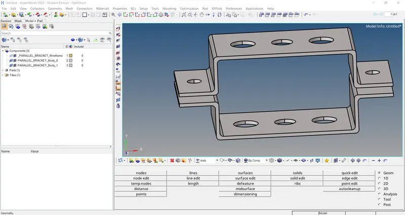
- The model (PARALLEL_BRACKET) was imported into the Hyperworks software.
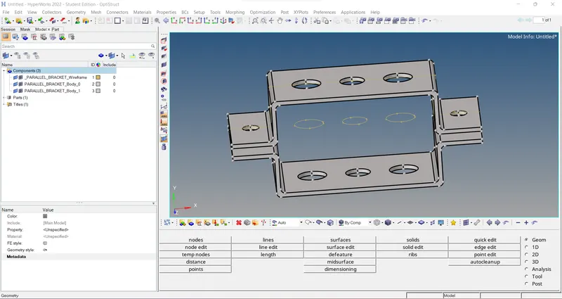
2. Then, need to extract mid surface for that go to Geom > mid-surface > auto mid-surface > auto extraction(surfs) > extraction options and set it to ‘offset + planes’ > go to auto extraction and select the surface (displayed) where the mid-surface to be created and extract.
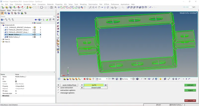
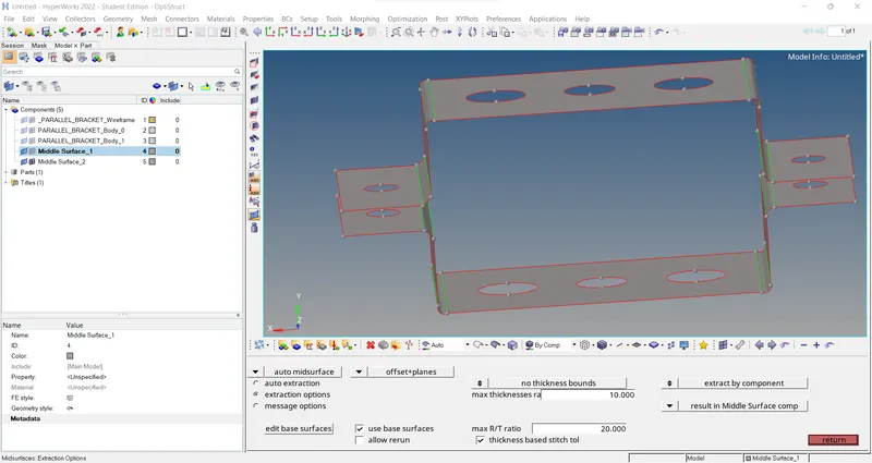
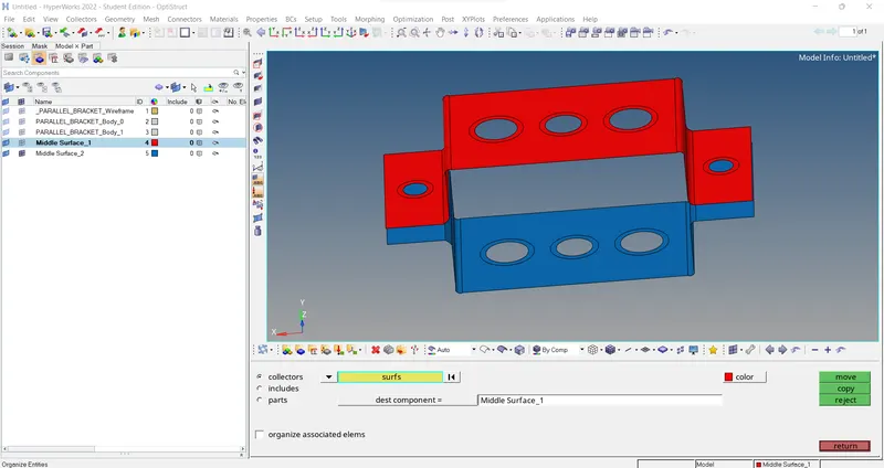
3. And create new component card as Bracket_1, Bracket_2 for upper and lower bracket Mid-surfaces separately.
[Note: Go to Tool > Organize > collectors > surfs > dest. component as Bracket_1/2 > select the lower surface > Move.]
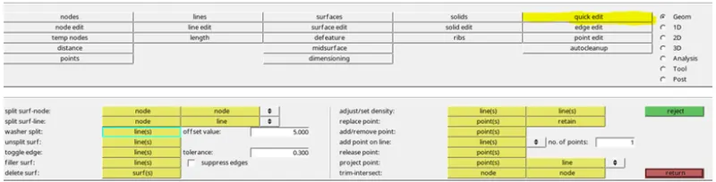
4. Then, hide the components which are not required and then go to Geom > quick edit > washer split (set offset value as 5mm) > select the circles on the surface to create washer split which will helps in creating finer mesh.
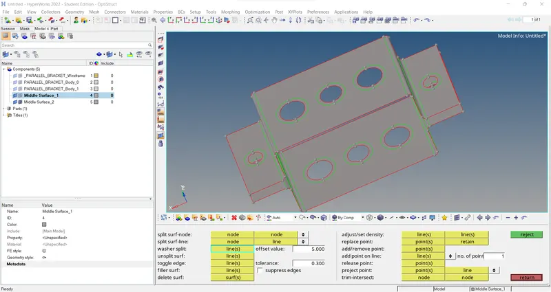
5. Go to 2D > Auto Mesh > Surfs > element size as 5mm > mesh.
[Note: make hole element number as similar as washer element number by left mouse click for increase and right click for decrease.]
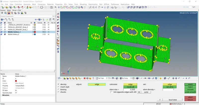
6. And also create the components and properties for Bracket_1, Bracket_2, Rod, Beam and Bar individually. And assign with proper image cards, material, and Beam sections. (Also in Materials create a default material for Bracket_1&2 and a steel material for rod, beam, bar.)

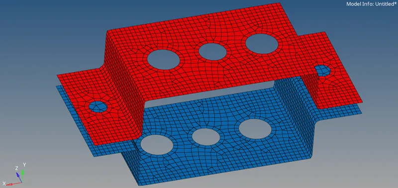
- Next, we are going to create links as given and for that go to 1D>Rigids (for Rbe2 links)>select multiple nodes and nodes by path option>click on the circle in a direction.
- for a. /Rod element (Cross-Section: ‘BOX’) -> Translational DOF should be Constrained with RBE2 link.
- for b. /Beam element (Cross-Section: ‘I’) -> All DOF should be constrained with RBE3 link.
- for c. /Bar element (Cross-Section: ‘X’) -> Constrain only x and y DOFs With RBE3 link.
- for d & e Apply the mass of magnitude 10 with the RBE2 link.
- and for f Join the two components with Spring elements.
RBE2 & RBE3 LINK CREATION ->
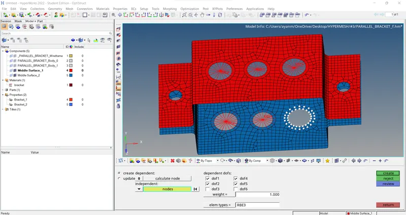
-> For a // Once the mesh was generated, RBE2 links were created. This was done by choosing the "Rigids > selecting nodes by the path and selecting multiple nodes > create". Translational DOFs were constrained according to the question. Similar steps were followed for the other connecting RBE2 link as well.
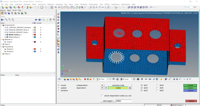
-> For b // RBE3 links were also created. This was done by choosing the "rbe3 > selecting nodes by the path and selecting multiple nodes > create". All DOFs were constrained according to the question. Similar steps were followed for the other connecting RBE3 link as well.
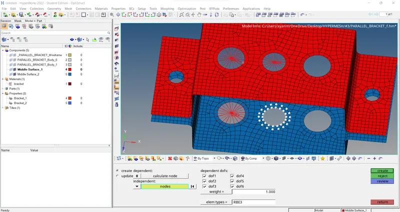
-> For c // Similarly, RBE3 links were again created. This was done by choosing the "rbe3 > selecting nodes by the path and selecting multiple nodes > create". Only x and y DOFs were constrained according to the question. Similar steps were followed for the other connecting RBE3 link as well.
1D Element Creation:
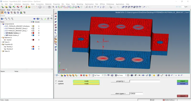
a) ROD Element -
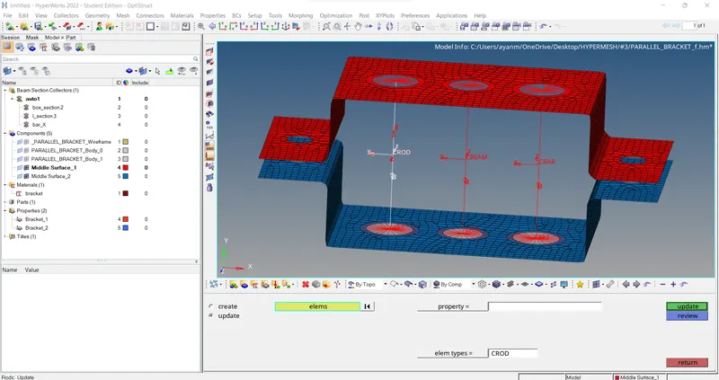
The ROD element was created by selecting the following commands "rods > nodes selection > CROD > create".
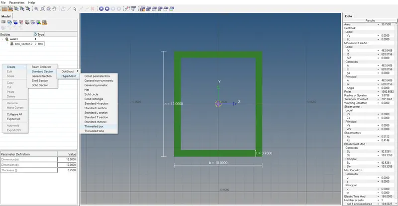
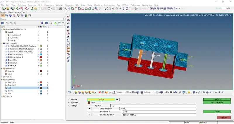
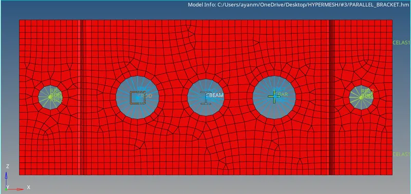
Once the element was created, it was crucial to assign the cross-section to the element. It was done by "1D > Hyper Beam > standard section > create". Then the Hyper beam windows opened and according to the question, a box of necessary dimensions was created. This was done by "create > standard section > Hyper mesh > thin-walled box". Then the properties of the ROD element had to be given > therefore, the property was created with "create > property > Card image = PROD > Beam section = box_section". Similar steps were applied for CBEAM and CBAR elements creation as well.
b) BEAM Element -
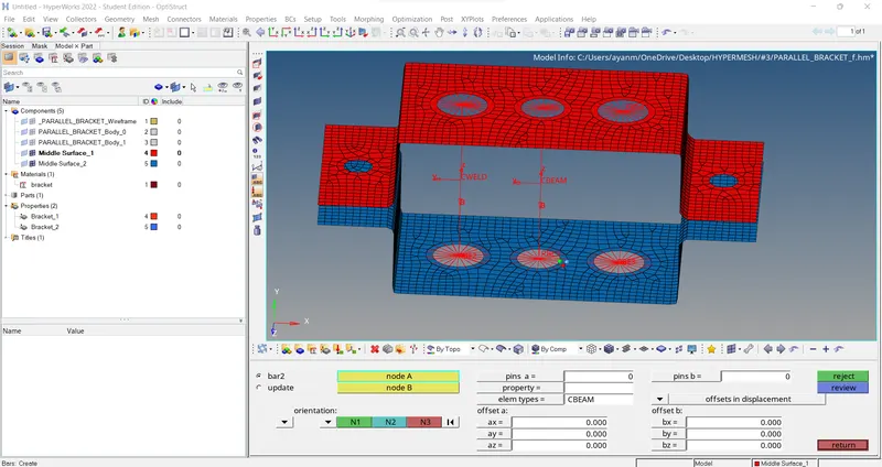
The BEAM element was created by selecting the following commands "bars > nodes selection > element type = CBEAM > orientation = nodes selection along axis > create".
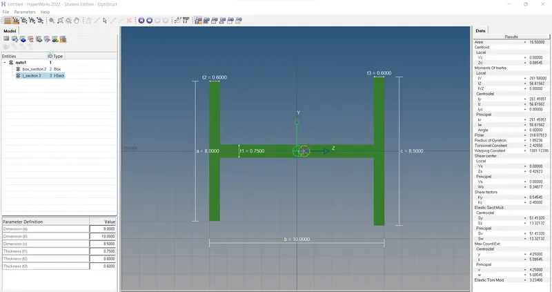
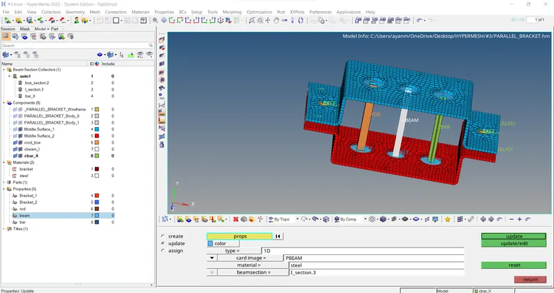
Once the element was created, it was crucial to assign the cross-section to the element. It was done by "1D > Hyper Beam > standard section > create". Then the Hyper beam windows opened and according to the question, an I-section of necessary dimensions was created. This was done by "create > standard section > Hyper mesh > I section". Then the properties of the Beam element had to be given > therefore, the property was created with "create > property > Card image = PBEAM > Beam section = I_section".
c) BAR Element -
The BAR element was created by selecting the following commands "bars > nodes selection > element type = CBAR > orientation = nodes selection along axis > create".
Once the element was created, it was crucial to assign the cross-section to the element. It was done by "1D > Hyper Beam > standard section > create". Then the Hyper beam windows opened and according to the question, an X-section of necessary dimensions was created. This was done by "create > standard section > OptiStruct > Cross". Then the properties of the Beam element had to be given, therefore, the property was created with "create > property > Card image = PBAR > Beam section = bar_X".
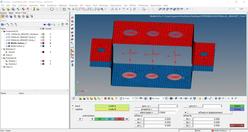
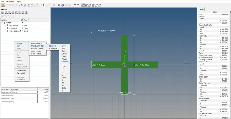
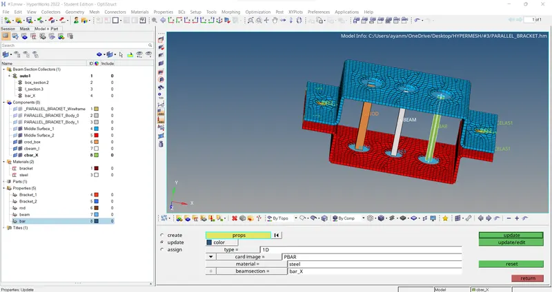
// [NOTE: Orientation also done for bar, beam, rod properly along with X-axis]
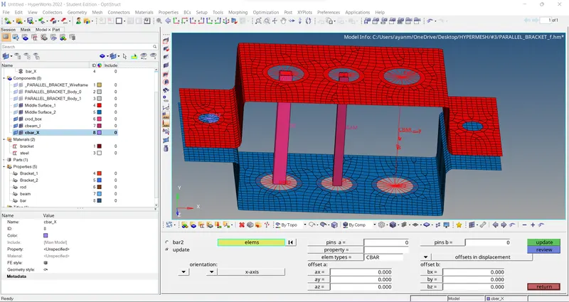 //
//
d & e) mass of magnitude 10 with the RBE2 link -
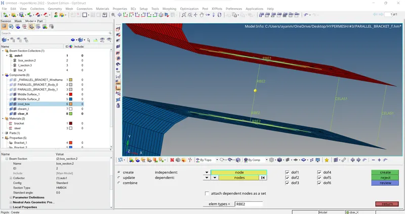
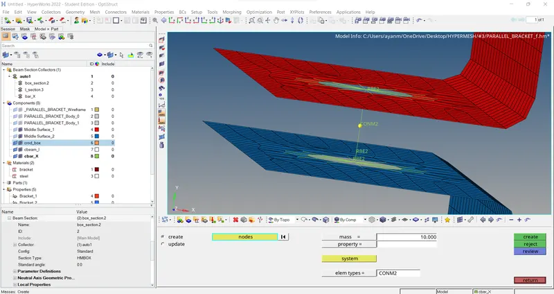
Once the mesh was generated, RBE2 links were created. This was done by choosing the "Rigids > selecting nodes by the path and selecting multiple nodes > create". The centre node of the link was selected and a mass of 10 was applied. This was done by "1D > mass > node selection > mass = 10 > element type = CONM2". Similar steps were applied for the other hole as well at ' e '.
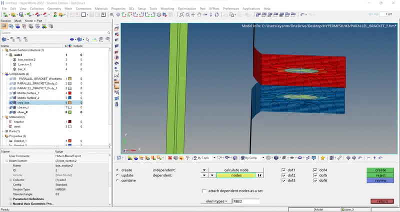
[Note: After creating RBE2 link in hole regions then go to geom > nodes > Interpolate nodes > select 2 master nodes of RBE2 link (for middle node creation) > Then again go to 1D > rigids (RBE2) > create link with master node & middle node for both side > After that go for 1D > masses > select middle node > mass = 10 / elem type = CONM2 create.]
f) Joining the two components by Spring elements -
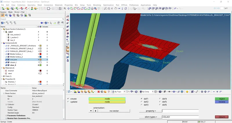
The Two components were joined by spring elements marked as ' f '. The spring elements were generated by “1D > selection of nodes > dof1 > element type = CELAS1“.
Results and Final Model Images:
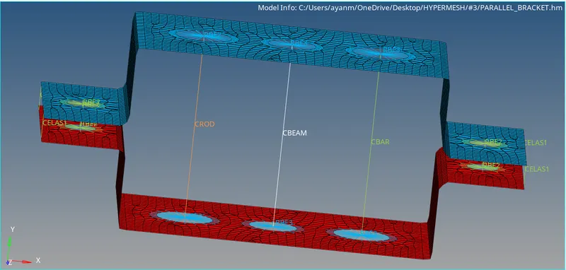
-> 1D Traditional element Representation ..
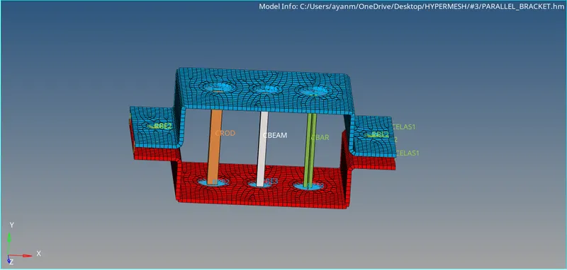
-> 1D Detailed element Representation ..
-> 1D detailed cross-sections BOX, I-sec and X-sec for ROD, BEAM, and Bar element respectively (left to right)…
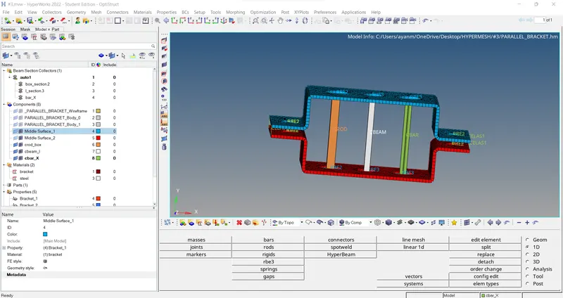
->> FINAL VIEW OF THE MODEL ....
CONCLUSIONs:
- Through this challenge I have learnt about how to extract the mid-surface and how to create rods, bars and beams.
- and also, about RBE2 links, RBE3 links and springs and got an idea about 1D element.
- And learnt to use some of the new commands in the Hyper Mesh tool like Hyper Beam, Mid-surface, Organize, RODs, BARS, rigids, Rbe3, springs, masses.
FINAL MODEL LINK ->
https://drive.google.com/file/d/1RKPbjAmd1omjREjqIB0XIC55dZlwscAh/view?usp=sharing