Week 4-1D Element Creation Challenge
AIM
TO take the midsurface of the given component and create 1D element with the given cross section in the component with given degree of freedom.
OBJECTIVE
* Generating mid surface of parallel bracket.
* Generating P Shell mesh on mid surface of parallel bracket.
* Creating 1D Element with given crossection and degree of freedom.
PROCEDURE
The process start with opening the hyperworks and select a solver, let it be optistruct. Then using the import option, we can import the component into the hypermesh. For that click on import and browse the directory for the CAD file of the component and then Click on import. Then the component gets imported to the hypermesh.
Then at first we need to delete the solids which may be presented in the component. For that we need to Go to DELETE panel and select the solid option, then by pressing CTRL +LEFT mouse button drag we can the displayed solids and then Hit DELETE. Then the solids will get deleted. And what we are left is the surfaces of the component.
Then we need midsurfacing of the component that we need to Go to geometry Panel>MIDSURAFCE>Select the Extraction options as oFFSET+PLANES+SWEEPS>Then click on AUTOEXTRACTION>Select the surfaces to midsurfacing .Select only the surfaces of one plate at a time, since after midsurfacing the bracket midsurface of the that plate will be obtained in a new collector. Then we should create a new collector and make it as current component and then do the midsurfacing of other plate. So that we can get the midsurfaces of each plate in two different collectors.
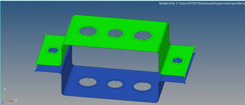
Midsurface of parellel bracket
Then we can 2D mesh the plates. For that go to2D >AUTOMESH>select the surface to mesh>hit MESH. The entire component will be meshed in this manner.
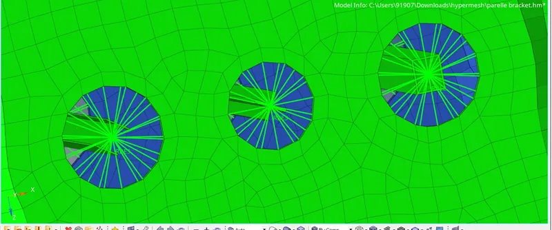
Then we need to create 1D element in the mesh. For that First create rod element .So first go to 1D panel>Select RBE2 and select the nodes around the circular washers and inside of washer as well. Then we need to specify the degree of freedom as dof 1, dof2, dof3 as unchecking ensuring the element have freedom in three translational axes .Then hit create
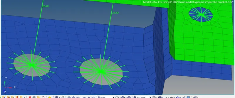
RBE2 cluster
Similar manner we need to create the RBE2 element in the bottom plate mesh as well. Then we will have a independent node and several dependent nodes in the RBE2 cluster. We need to go to 1D>ROD>select the independent nodes of the RBE2 cluster and Hit CREATE. Then we can see the CROD is formed. Similarly we need to CREATE RBE3 element cluster in the next hole and uncheck all the dof so that the element will be having all the directional freedoms. Then we can choose the independent nodes to form the CBEAM element. For that Go to 1D>BEAM>select the independent nodes>hit CREATE.
Similarly CREATE RBE3 cluster in the third hole and use the independent nodes to create BAR element. Go to 1D>RBE3>uncheck dof1, dof2 >select the nodes in the hole>hit CREATE.
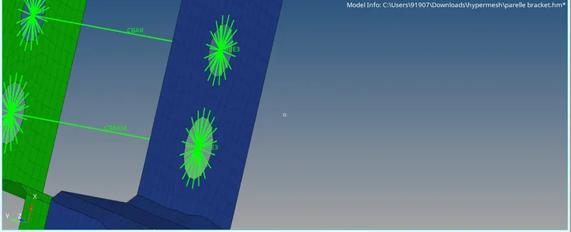
RBE3 cluister
Then at the position d and e, we need to create a RBE2 element cluster with all sorts of degree of freedoms. For that Go to 1D >select RBE2 >uncheck all DOF > select the nodes around the holes at d and e>hit CREATE.
We need to apply mass of 10 magnitude at d and e, so we need to GO to 1D>MASSES>select the independent nodes at d and e of RBE2 cluster of links. Then choose ELEMENT TYPE as CMASS1.We need to connect the two bracket plates with SPRING elements. For that go to1D>SPRINGS> choose the nodes off the mesh at the f region of two plates> hit CREATE.
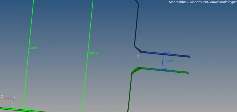
CELA1 spring element
What next is to create the cross sections for the ROD,BAR and BEAM. For that go to 1D>HYPERBEAM.In hyperbeam Left click on entities side >CREATE>STANDARD SECTION>OPTISTRUCT>BOX> Input dimensions into the value spaces.Similarly create Beam element with I Section by Go to Left click on entities side >CREATE>STANDARD SECTION>HYPERMESH>STANDARD I SECTION>> Input dimensions into the value spaces.Similarly go to Left click on entities side >CREATE>STANDARD SECTION>OPTISTRUCT> CROSS> Input dimensions into the value spaces for beam element.
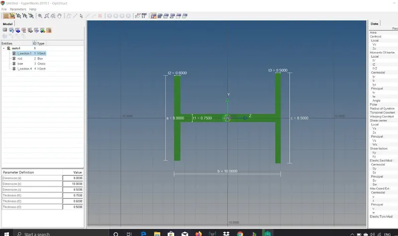
I - section in hyperbeam
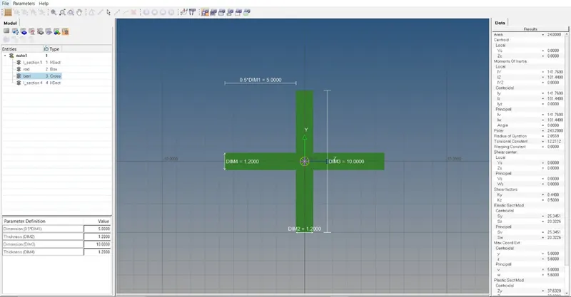
cross- section in hyperbeam
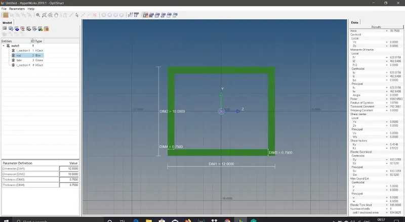
box -section in hyperbeam
CROD elements support tension and compression only, whereas CBARS and CBEAMS allow bending as well. A CBAR element is a kind of simplified CBEAM element and should be used whenever the cross-section of the structure and its properties is constant and symmetrical. The CBAR element requires that its shear center and the neutral axis coincide. Due to this requirement CBAR elements are not useful for modeling structures that may warp, such as openchannel-sections. This limitation is not present in CBEAM elements.
We need to create a new material as steel and gives inputs like rho,nu,Modulus of eleasticity etc..
Then CREATE 3 properties for bar ,rod and beam in the model browser.
From the drop down list of properties,edit each properties and change card image to PROD,PBEAM,PBAR and beam section to rod,beam,bar respectively to ROD,BEAM and BAR.And also assign material to each of the properties.
To view the crosss sections of elements in the hypermesh,Switch to 1d detailed reprensentation.
RESULT
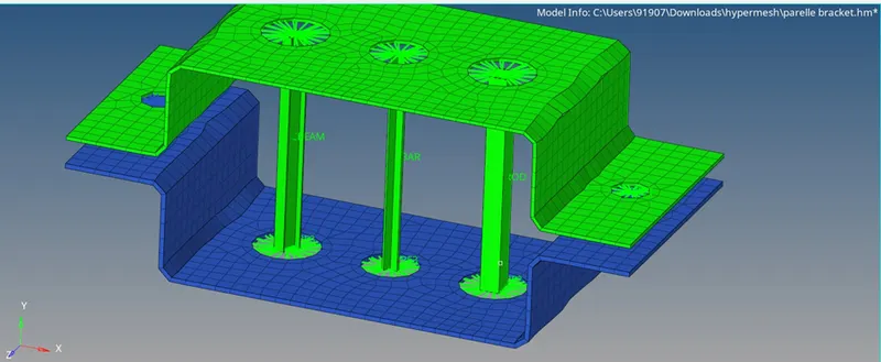
After creating bar,beam and rod.
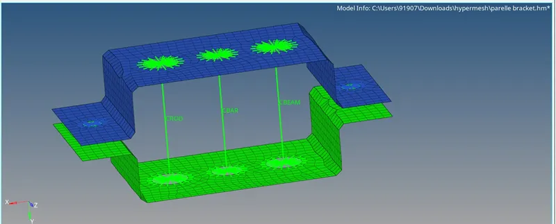
Viewing the cross section of elements in detailed representation.