Week 4-1D Element Creation Challenge
AIM:Mesh the Given component with the Size of 5 Units. Create 1D elements on the following component with given cross-section and DOF.
a. Rod element:- Translational DOF should be Constrained with RBE2 link
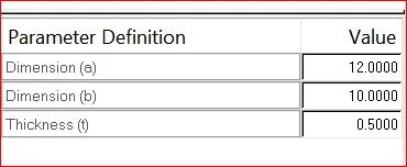
Cross-Section: BOX- Dimension a= 12 mm
dimension b=10 mm
Thickness t= 0.75 mm
b. Beam element:- All DOF should be constrained with RBE3 link
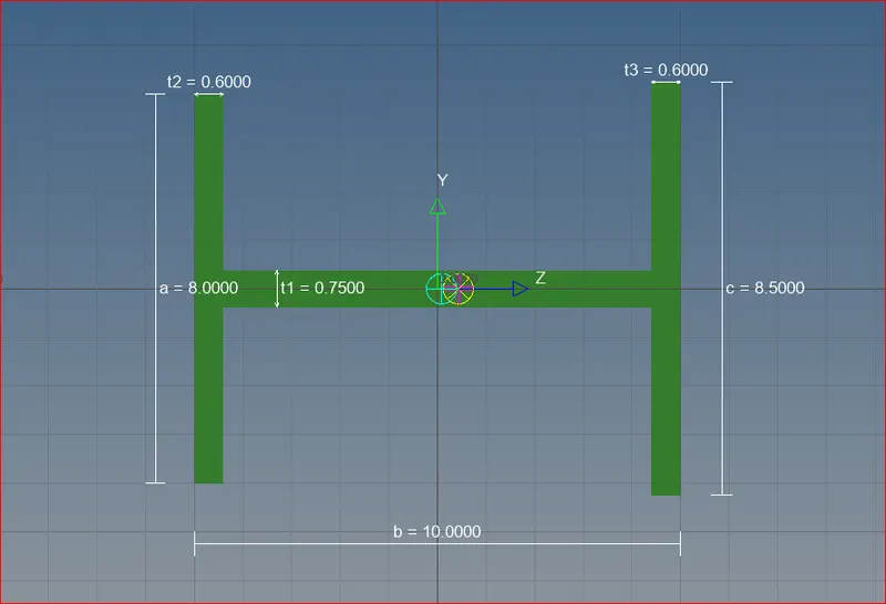
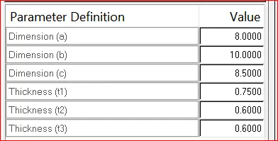
Cross-Section: I Section- Dimension a= 8 mm
Dimension b= 10 mm
Dimension c= 8.5 mm
Thickness t1= 0.75 mm
Thickness t2= 0.6 mm
Thickness t3= 0.6 mm
c. Bar element:- Constrain only x and y DOFs With RBE3 link
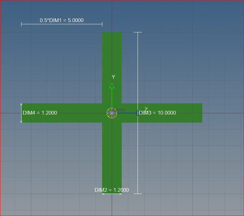
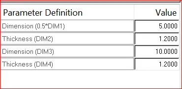
Cross-section: X section- Dimension DIM1= 5 mm
Thickness DIM2= 1.2 mm
Dimension DIM3= 10 mm
Thickness DIM4= 1.2mm
d. & e. Apply the mass of magnitude 10 with the RBE2 link
f. Join the two components with Spring elements.
SOFTWARE USED: Altair Hypermesh.
About Software: Optistruct-Hypermesh is software which is used in CAE domain. it is mainly used for Meshing of 1D,2D,3D, elements and Connections.Iti is a preprocessor which is used by many Automobile companies.
PROCEDURE:
1) IMPORT A CAD GEOMETRY.
2) GEOMETRY CLEANUP
3)SKIN/MID SURFACE GENERATION.
4)SHELL/SOLID MESHING. (THICKNESS DEPENDENCY).
5)ELEMENTARY QUALITY CHECK.
6)MESH IMPROVEMENT
7)APPLY LOAD & BOUNDARY CONDITIONS.
8)EXPORT INPUT FILE.
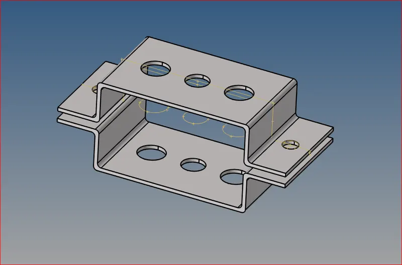
1) IMPORT A CAD GEOMETRY : This is the first step in any preprocessor software either Ansa or Hypermesh. we need to import a cad model weather it is a step file or iges or hm.
below figure represents the cad model importing.
2) GEOMETRY CLEANUP:After importing a cad model due to software isssues , some issues occurs in the cad model like sharp edges, holes, extra cons, triple,single, double,etc.As a CAE engineer we need to resolve all the issues by auto cleanup tool in Hypermesh.
3)SKIN/MID SURFACE GENERATION: This is the step we need to decrease the computational time by reducing the thickness with result accuracy. by decreasing the thickness is nothing but a shell element. in order to produce shell, there is a option in hypermesh is mid surface -automid-surface extraction.
4)SHELL/SOLID MESHING. (THICKNESS DEPENDENCY): After successfully producing/extracting a mid surface we need to create a mesh on it.by meshing there is seperate option is Auto-Mesh by using that tool we create meshing on the two brackets. so we have to create different property for two brackets for more visibility and understanding. by creating the two pid's after, go to organise and assign property of component which property we want. and after assign material, colour, thickness etc.
below figure reresent the meshing of a component.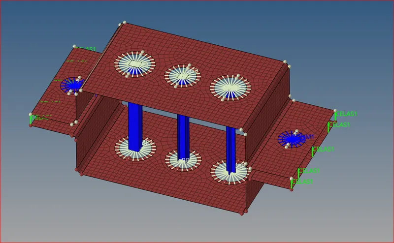
5)ELEMENTARY QUALITY CHECK: In this we need to assign some quality parameters ,but for this component there is no quality criteria and mesh parameters.
but in the question they menctioned mesh size as 5 units. so we created mesh as per the requirement.
6)MESH IMPROVEMENT: In this we will work on mesh improvement means if necesaary we will create some brackets at nearer to the holes.
- Is there any opposite trias we need to remove.
- If there any trias touching each other we need to remove.
- If there is any tria in the feature line we need to remove.
- if there is any rotational quads we need to remove.
- if there is any rotational tria we need to remove.
These factors will helping to improve mesh.
As per the question i created rod, beam, and bar.
firstly i created a rod with BOX cross section.below figure represents the box.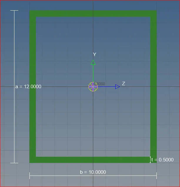
secondly i created a beam with I cross section.below figure represents the i.
finally i created a bar with X cross section.below figure represents the x cross section.
After creating the cross sectons i created rbe2,rbe3, springs and, bar,rod, beams ,and masses according to question.
After assigning the all the elements the figure shown below.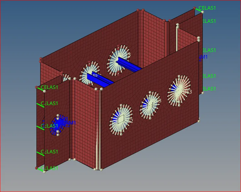
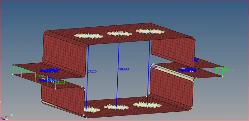
RESULTS: As per the question menctioned.
- I imported cad model.
- I done geometry clean up.
- I extracted a mid surface.
- I created a meshing.
- I done with cross sections- BOX, X, I.
- I done connections with required mass where it is required such as ROD,BEAM,BAR,RBE2,RBE3,SPRING,MASS.
- I created property for each component and rigid elements.
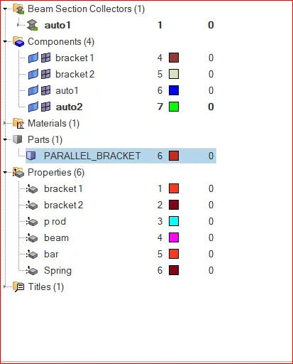
- Below figure repreents the detailed view of property, material, assigned thickness etc.