Week 4-1D Element Creation Challenge
Objective : 1) To study & perform midsurface extraction in hyperworks.
2) Create 1D elements on the given component with different cross sections and DOF
Midsurface:
Midsurface is nothing but the surface between the two surfaces.The midsurface is a 2D representation of 3D or solid objects
Import the model:
1. Firstly, model needs to be imported in hyperworks desktop.
2. Followed by the path as import geometry > select IGES > select the model file.
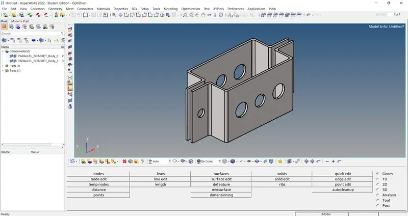
Extract midsurface:
Step 1:Selected the geometry tools option in main menu page.
Step 2:Selected midsurface tool.
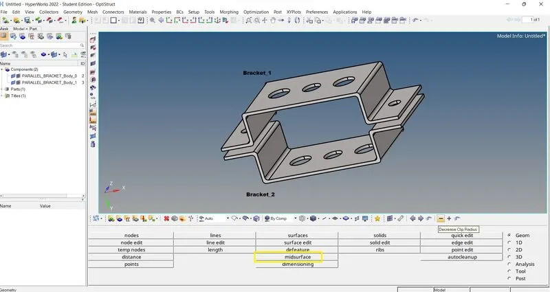
Step 3: Selected the surface of the ‘bracket_1’ and selected extract
Step 4:The midsurface was extracted and renamed it as Bracket_1
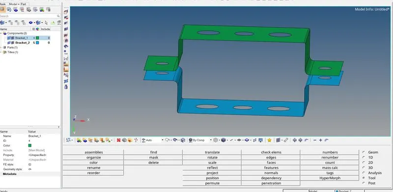
Step 5: In model view window followed the path as : create > material and a new component was created as Bracket_2
Step 6: Repeated the procedure from step 1 to step 4 for ‘bracket_2’
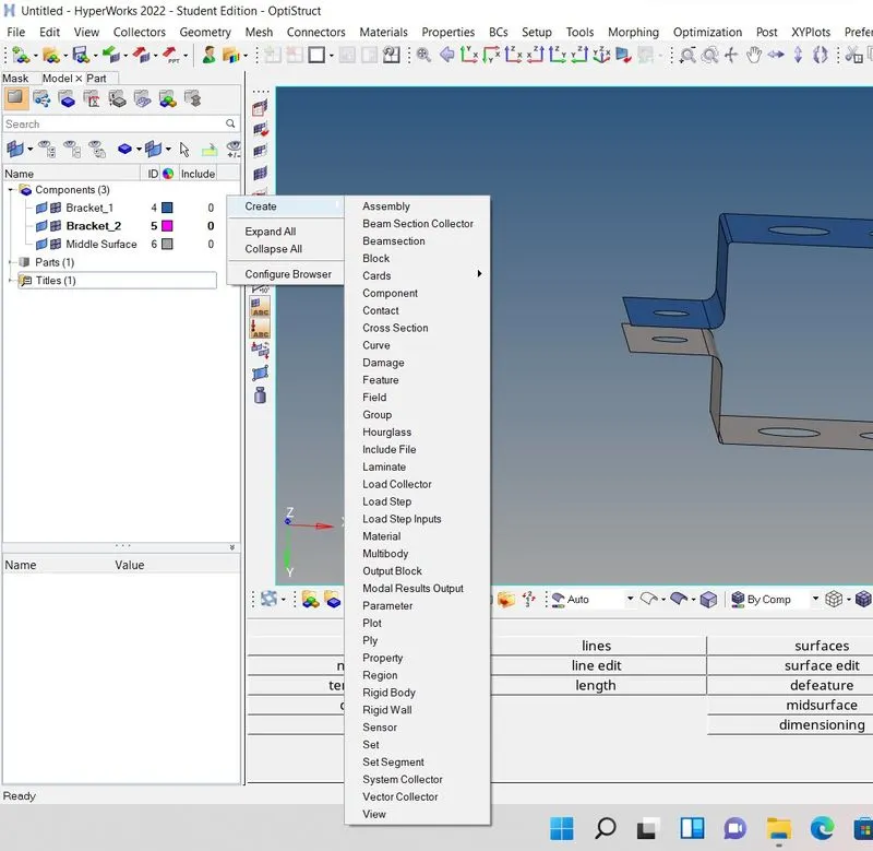
Move midsurface under component created:
Step 1: selected the Tool option in main menu page
Step 2: Selected midsurface of ‘bracket_1’ component under surface tab and selected move.

Step 3: Delete solid objects bracket_1’ and bracket_2’
Create material:
Step 1: In model view window followed the path as : create > property
Step 2: Renamed it as Steel.
Step 3: Selected the card image defining the steel material.
Create property:
Step 1: In model view window followed the path as : create > property
Step 2: Renamed it as Bracket_1and Bracket_2
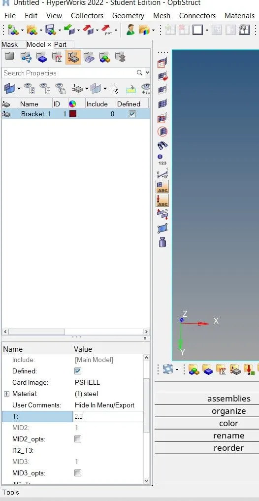
Step 3: selected the card image as PSHELL and material as steel.
Step 4: assigned thickness of 2 and 2.5 to bracket_1 & bracket_2 respectively.
Assign the property to the component:
Step 1: Selected the Bracket_1 and Bracket_2 component in model view.
Step 2: respective property was specified to the respective component.
Create mesh:
In order to create mesh, washer split was created for holes to ensure proper mesh
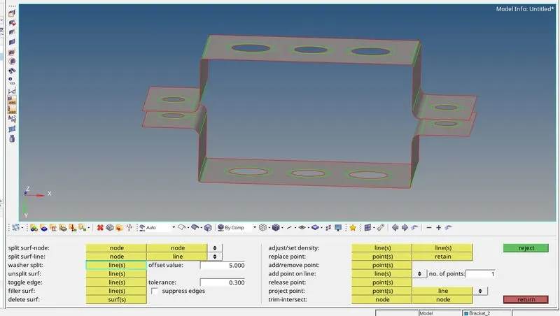
Step 1: In main menu page, selected 2D option and automesh tool was selected
Step 2: Selected the surfaces of both the component
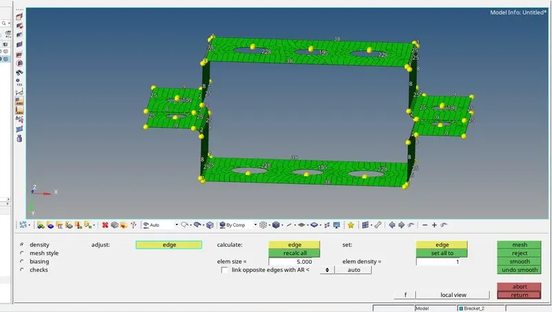
Step 3: Selected the mesh size as 5 and mesh type as mixed and selected mesh.
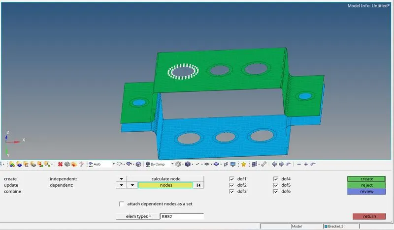
Create RBE2 link at washer a:
Step 1: Followed the path as main menu page>1D>rigids
Step 2: Selected create option and set nodes selection option as multiple nodes and calculate mode.
Step 3: Selected element type as RBE 2
Step 4: Deselected dof1, dof2 and dof3 to give only translational DOF (degree of freedom).
Step 5: Selected create option.
Create RBE2 link at washer d & e:
Step 1: Followed the path as main menu page>1D>rigids
Step 2: Selected create option and set nodes selection option as multiple nodes and calculate mode.
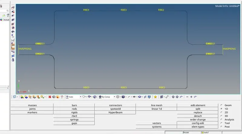
Step 3: Selected element type as RBE.
Step 4: Deselected dof1, dof2 and dof3 to give only translational DOF (degree of freedom).
Step 5: Selected create option.
Create RBE3 link at washer b and c:
Step 1: Followed the path as main menu page>1D>RBE3
Step 2: Selected create dependent option and set nodes selection option as multiple nodes and calculate node
Step 3: Deselect all dofs to give DOF in all direction at washer b.
Step 4: Deselect dof1 and dof2 to give DOF in only X and Y direction.
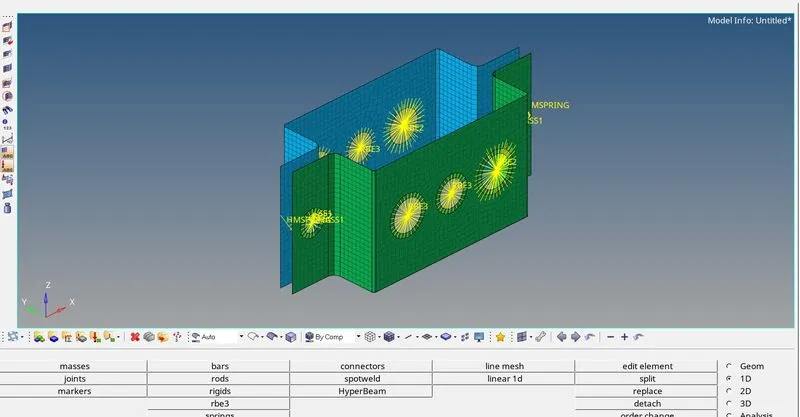
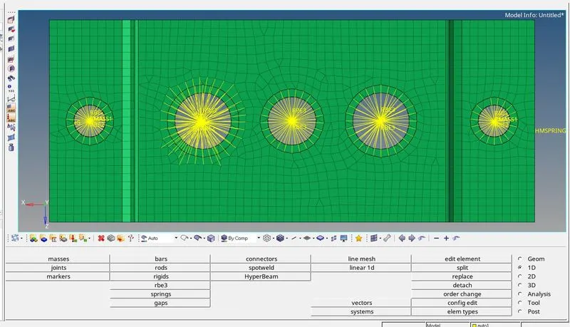
Create Bar, Rod and Beam sections:
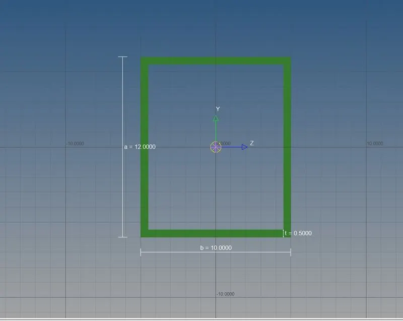
Create Bar section:
Step 1: Followed the path as main menu page>1D>HyperBeam

Step 2: Selected the standard section and selected section type.
Step 3: Selected create tab and HyperBeam window was opened.
Step 4: Followed path as create>standard section>hypermesh>Thinwalled box
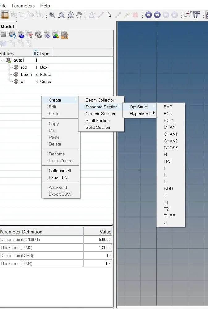
Step 5: Given dimensions were applied to the section.
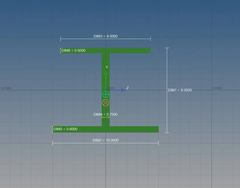
Create I section Beam:
Step 1: Followed the path as main menu page>1D>HyperBeam
Step 2: Selected the standard section and selected section type.
Step 3: Selected create tab and HyperBeam window was opened
Step 4: Followed path as create>standard section>hypermesh>Standard section
Step 5: Given dimensions were applied to the section.
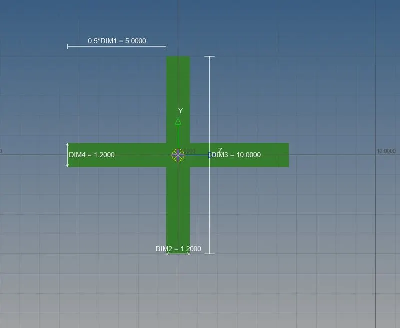
Create Cross cross section:
Step 1: Followed the path as main menu page>1D>HyperBeam
Step 2: Selected the standard section and selected section type
Step 3: Selected create tab and HyperBeam window was opened.
Step 4: Followed path as create>standard section>Optistruct>Cross
Step 5: Given dimensions were applied to the section
Create properties for Bar, Rod and Beam elements:
Step 1: In model view window followed the path as: create > property
Step 2: Created property for each rod, bar and beam element with same name respectively.
Step 3: Selected card image as:
PROD for Rod
PBAR for Bar
PBEAM for Beam
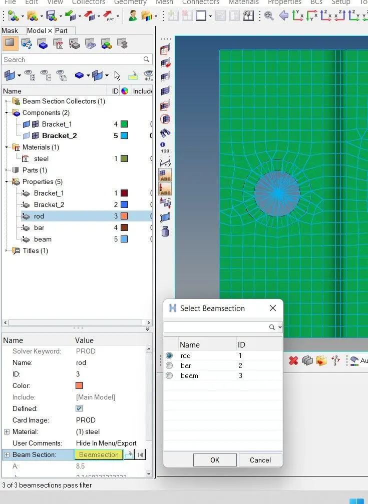
Step 4: Selected cross section for respective property.
Create Rod element at washer a:
Step 1: Followed the path as Main menu page>1D>Rods.
Step 2: Selected create option and selected the start and end nodes.
Step 3: Selected property as rod and element type as CROD and rod element was created.


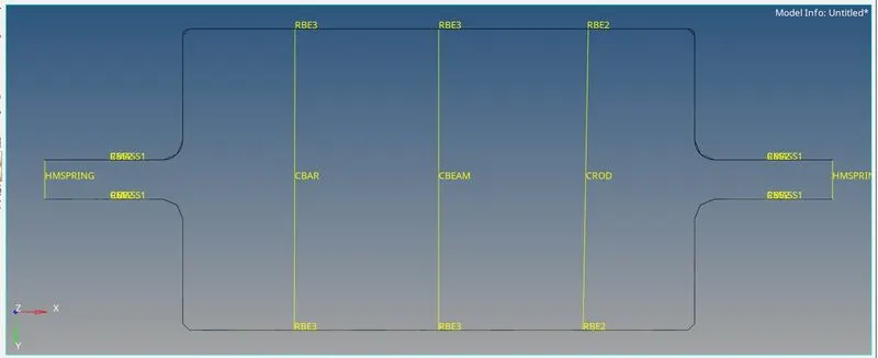
Create Beam element at washer b:
Step 1: Followed the path as Main menu page>1D>bars
Step 2: Selected bar2 option and selected the node A and node B.
Step 3: Selected property as Beam and element type as CBEAM
Step 4: Selected N1, N2 and N3 nodes for orientation and Beam element was created.
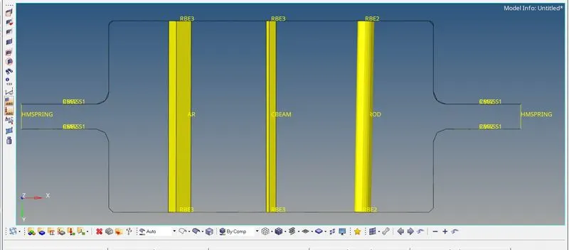
Create Bar element washer c:
Step 1: Followed the path as Main menu page>1D>bars
Step 2: Selected bar2 option and selected the node A and node B.
Step 3: Selected property as Bar and element type as CBAR
Step 4: Selected N1, N2 and N3 nodes for orientation and BAR element was created
Apply mass at washer d & e:
Step 1: Followed the path as Main menu page>1D>masses
Step 2: Selected create option and selected node
Step 3: Selected create option and selected node
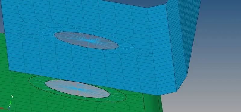
Step 4: Specified magnitude of 10.
Step 5: Selected element type and selected create.
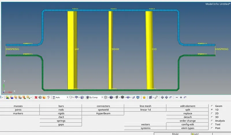
Final Model:
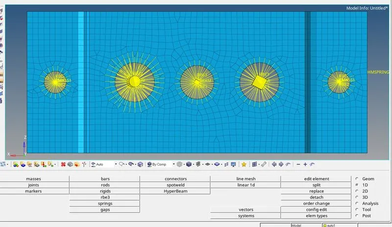
Conclusion:
We successfully extracted midsurface and created 1D elements on given model with given cross section and DOF.