Week 4-1D Element Creation Challenge
Mesh the Given component with the Size of 5 Units. Create 1D elements on the following component with given cross-section and DOF
a. Rod element:- Translational DOF should be Constrained with RBE2 link
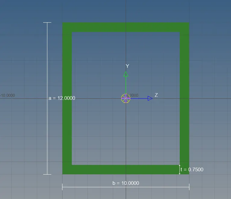
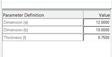
Cross-Section: BOX- Dimension a= 12 mm
dimension b=10 mm
Thickness t= 0.75 mm
b. Beam element:- All DOF should be constrained with RBE3 link
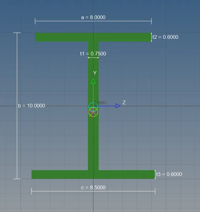
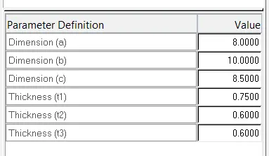
Cross-Section: I Section- Dimension a= 8 mm
Dimension b= 10 mm
Dimension c= 8.5 mm
Thickness t1= 0.75 mm
Thickness t2= .6 mm
Thickness t3= .6 mm
c. Bar element:- Constrain only x and y DOFs With RBE3 link
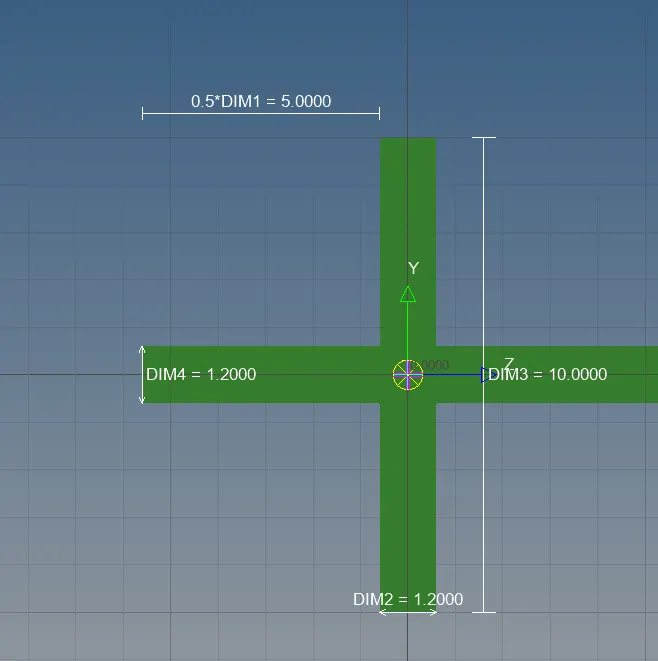
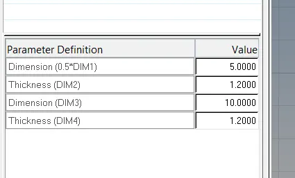
Cross-section: X section- Dimension DIM1= 5 mm
Thickness DIM2= 1.2 mm
Dimension DIM3= 10 mm
Thickness DIM4= 1.2mm
d. & e. Apply the mass of magnitude 10 with the RBE2 link
f. Join the two components with Spring elements
ANS:-
OBJECTIVE:-
Meshing the given model and creating 1d element for given cross section and dof.
Procedure:-
1. creating mid surface
2. meshing.
3. rigiding nodes
4. creating 1 D models
5. applying 1D models
1. creating mid surface:-
creating mid surface with command geometry>midsurface>auto midsurface selecting the component. as shown in figure
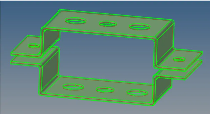
after this hiding the model and keeping only midurface in display.
2. meshing:-
before meshing washer-split is done
after midsurfacing meshing is done 2D>automesh>elementsize>
later nodes of holes and washer are matched.
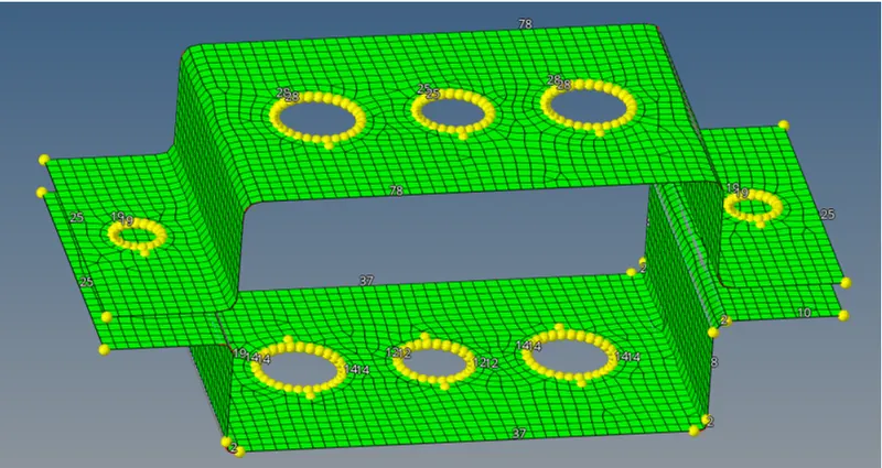
colors of different component changed in model
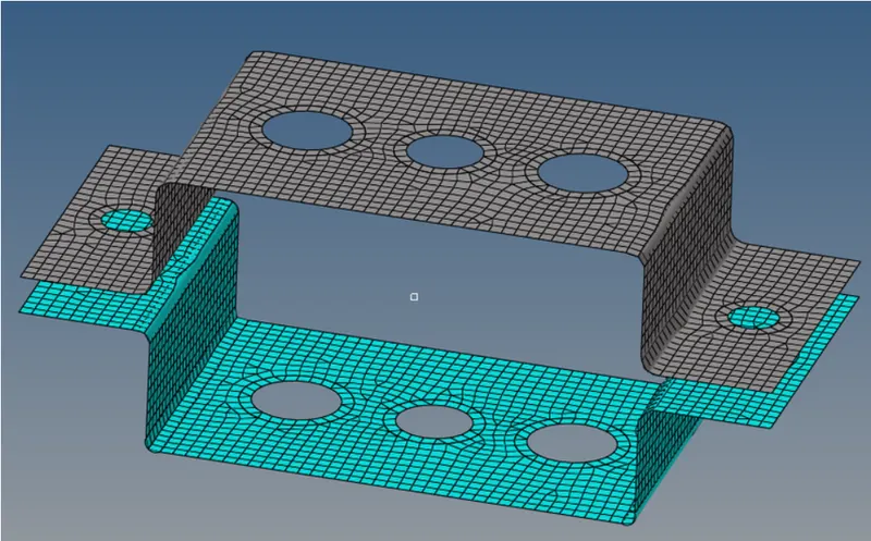
3. rigiding nodes
after successfully completing the meshing holes is to be rigid.
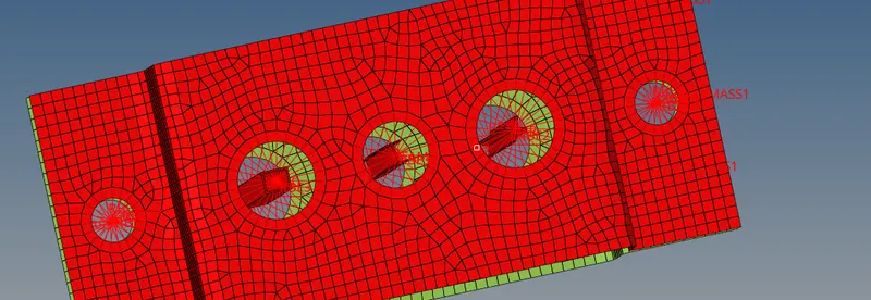
for RBE2- 1D>rigids>calculatenodes>nodes selesction by path.
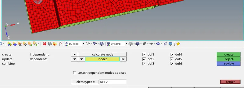
for RBE3- 1D>RBE3>calculatenodes>path selection

for spring - 1D>springs>node1>node2.

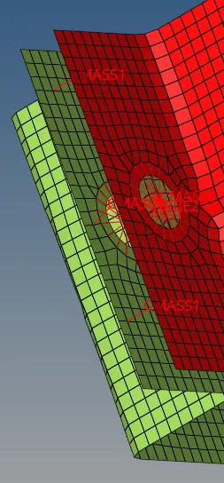
4. creating 1 D models
creating 1D elements hyperbeam>liabfrary>optistruct/hyperbeam>standard section>selecting cross sections.


ROD ELEMENT>BOX SECTION
BEAM ELEMENT> I SECTION
BAR ELEMENT> X SECTION
5. applying 1D models
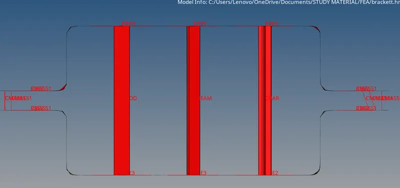
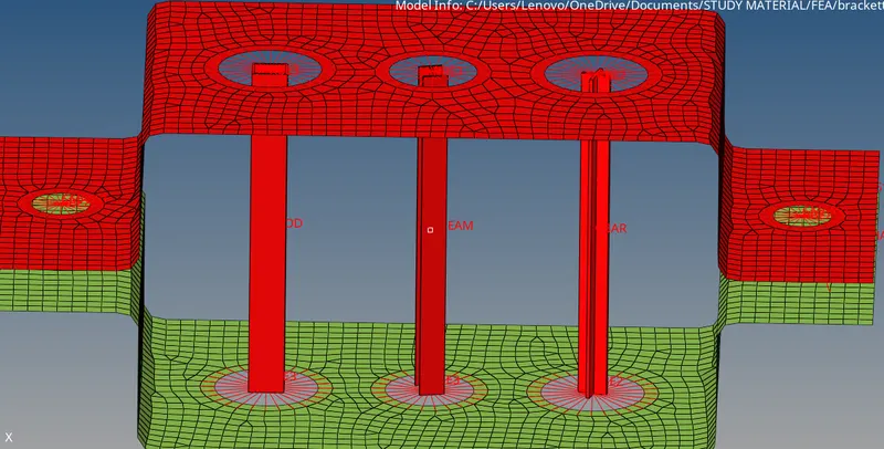
FINAL IMAGE:-
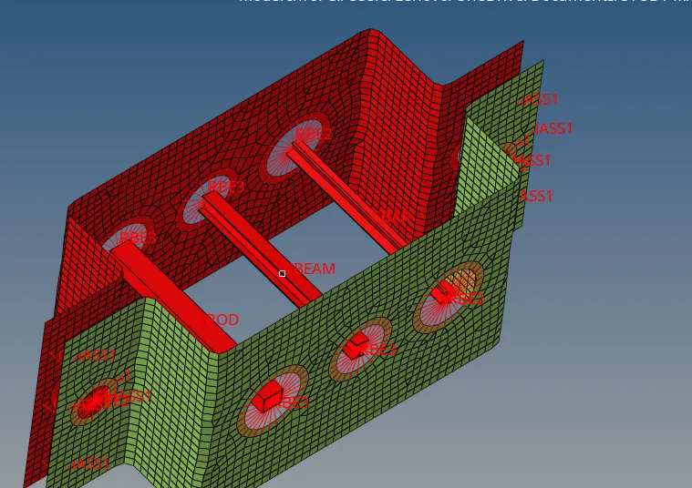
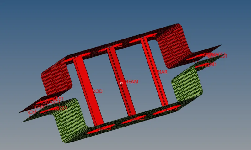
RESULTS:-
attempted the challenge for meshing and creating 1D elements and completed successfully.
model of .hm file is attached for reference.