Week 4-1D Element Creation Challenge
Assignement-3
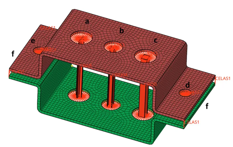
Objective: To mesh a given component and create 1D elements on meshed component with cross-section as shown in below image.
Also join the two components using spring elements and assign point mass at the given locations.
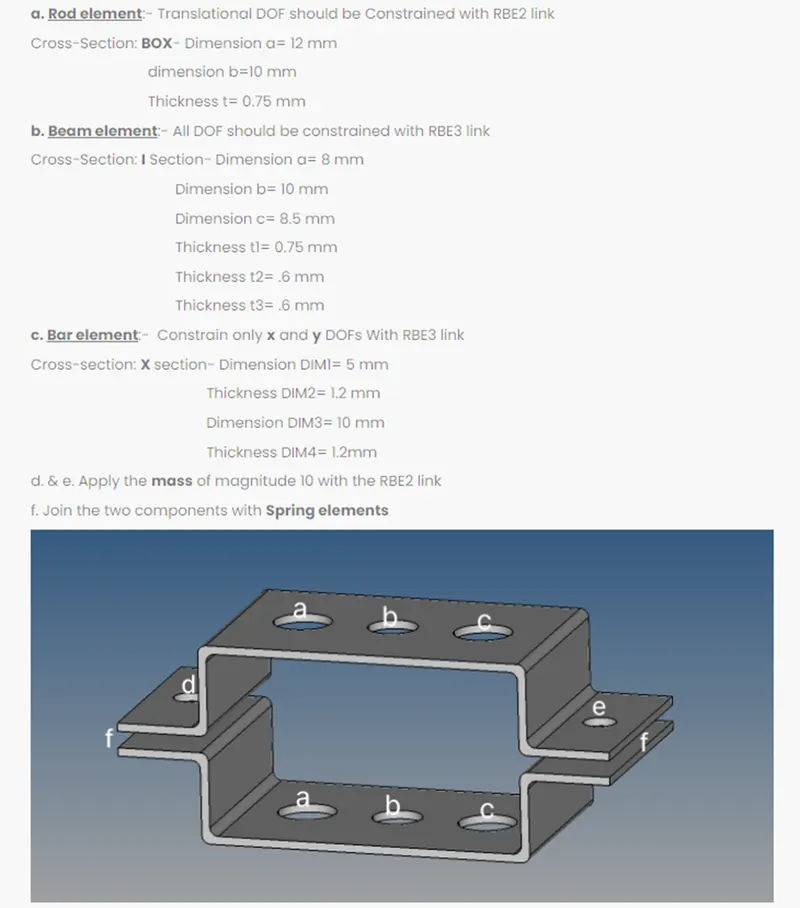
Description:
- Import the geometry.
- Delete all the unnecessary line
- Then extract mid surface out of the solid model
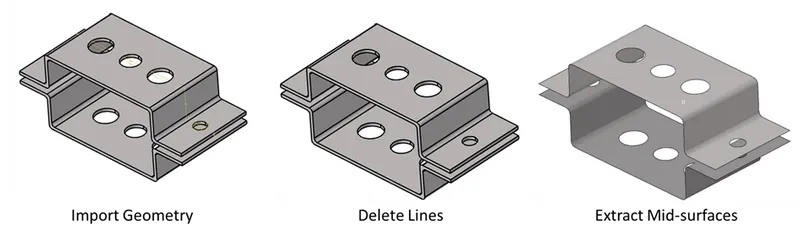
- In order have good mesh, split surfaces in the fillet regions
- Mesh the surfaces using elements of size 5 units
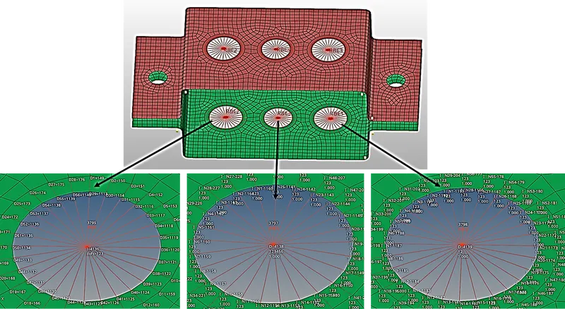
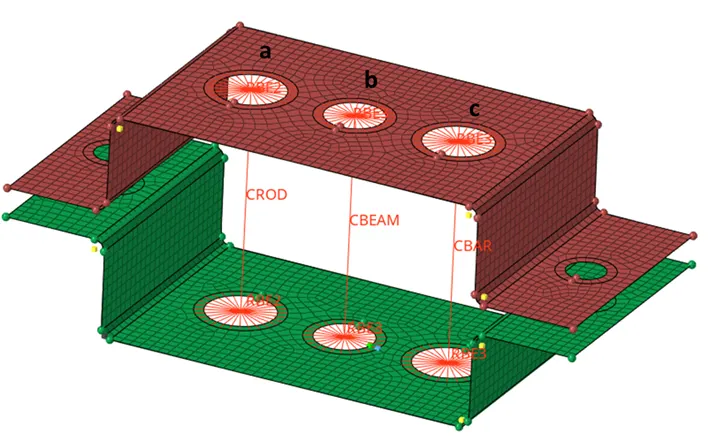
- As stated in the objective, create links/spiders of RBE2 and RBE3 at the respective locations
- Ensure that the RBE2 has only translational DOF constrained and RBE3 has all the DOF constrained in one of the link and other RBE3 link has only X and Y DOF constrained. This can be seen in the image below.
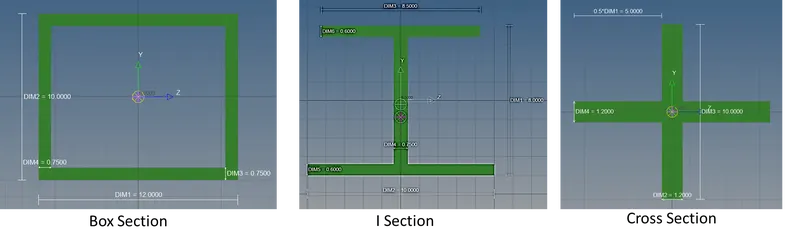
- Next create Rod, Beam and Bar element at the position a, b, c as stated in the objective.
- Using hyperbeam create box, I and cross cross-section for the rod, beam and bar element respectively.
- Then define steel material using material card image MAT1. Define young’s modulus, poisson’s ratio, shear modulus and density for steel.
- Next create property for shell element and assign 5 unit thickness with material definition as steel.
- Similarly created property for rod, beam and bar as well as define material as steel.
- The properties created has to be then assigned to the respective components using update command.
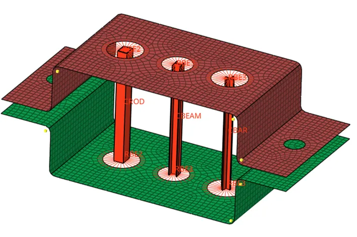
- To visualize cross-section turn on 1D detailed element representation option
- Next create RBE2 link at location d and e to define point mass of 10 units.
- Point mass is defined by creating cmass with property image card pmass.
- Finally connect upper and lower brackets using spring elements. This is done by defining celas1 element with property card pelas having appropriate spring stiffness.
Results:
The final model obtained is as shown