Week 4-1D Element Creation Challenge
Questions:
A].
Mesh the Given component with the Size of 5 Units.
B].
Create 1D element of following specifications with given cross-section and DOF.
Rod element:- Translational DOF should be Constrained with RBE2 link
Cross-Section: BOX- Dimension a= 12 mm
dimension b=10 mm
Thickness t= 0.75 mm
C].
Create 1D element of following specifications with given cross-section and DOF.
Beam element:- All DOF should be constrained with RBE3 link
Cross-Section: I Section- Dimension a= 8 mm
Dimension b= 10 mm
Dimension c= 8.5 mm
Thickness t1= 0.75 mm
Thickness t2= .6 mm
Thickness t3= .6 mm
D].
Create 1D element of following specifications with given cross-section and DOF.
Bar element:- Constrain only X and Y DOFs With RBE3 link
Cross-section: C section- Dimension DIM1= 5 mm
Thickness DIM2= 1.2 mm
Dimension DIM3= 10 mm
Thickness DIM4= 1.2mm
E].
Apply the mass of magnitude 10 with the RBE2 link.
F].
Join the two components with Spring elements.
Solution:
A].
Mesh the Given component with the Size of 5 Units.
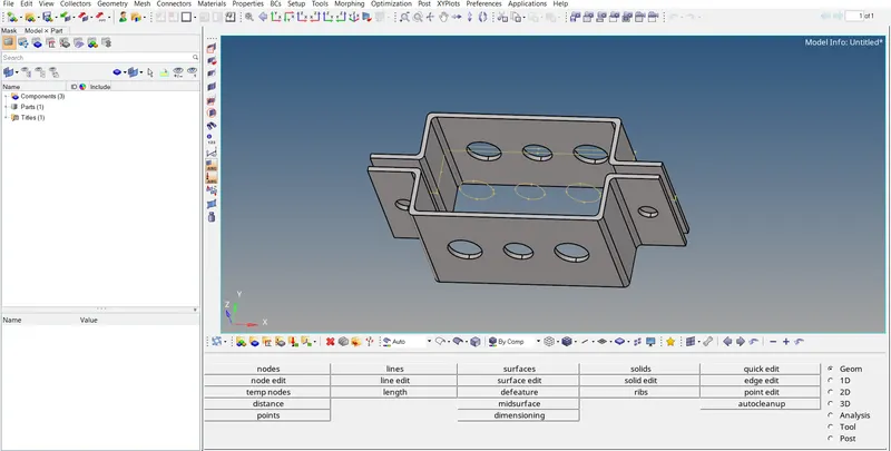
Figure1.1: Import the model in Hyperworks.
Firstly import the IGES file of the model into the Hyperworks.
Now let's extract the midsurface of the component in order to represent the shell elements.
Shell elements are nothing but the 2D representation of the 3D elements.
Let's say the upper frame is bracket-1 and the lower frame is bracket-2.
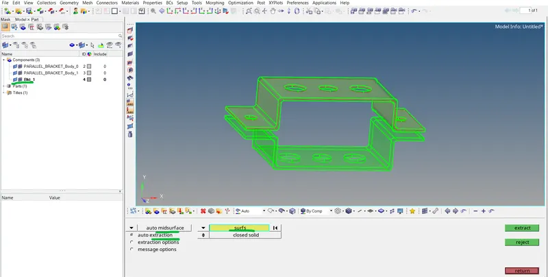
Figure1.2: Extracting the midsurface component of bracket-1.
For extracting the midsurface of bracket-1:
Goto => Geometry => midsurface => auto midsurface => auto extraction => surfaces => select 'bracket-1' => 'extract'
Rename that midsurface component as 'Bkt_1'
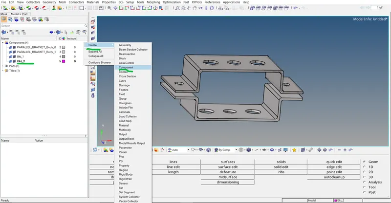
Figure1.3: Creating component and renaming it as Bkt_2'.
Before we create the midsurface for bracket-2 we must create the component and rename it as 'Bkt_2'
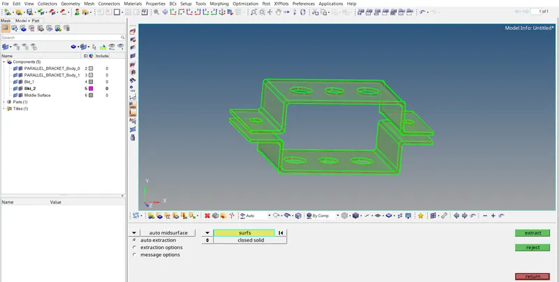
Figure1.4: Creating midsurface for bracket-2.
Now we will create the midsurface for bracket-2.
For extracting the midsurface of bracket-2:
Goto => Geometry => midsurface => auto midsurface => auto extraction => surfaces => select 'bracket-2' => 'extract'
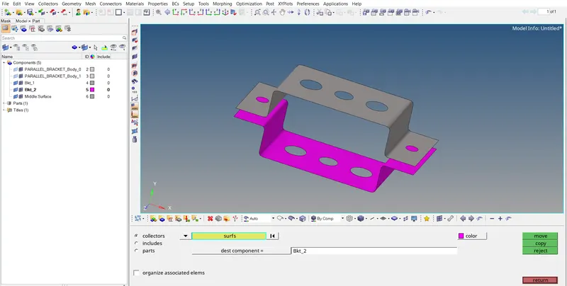
Figure1.5: Move the midsurface of bracket-2 to component 'Bkt_2'.
For moving the surfaces:
Goto => Tools => Organize => collectors => surfaces => select surfaces of bracket-2 => 'move'
Make sure the current model must be the component we are moving our surfaces to i. e. Bkt_2. While selecting the surfaces of bracket-2 colour remains white but after execution colour changes to the pink i. e. colour of the current model Bkt_2.
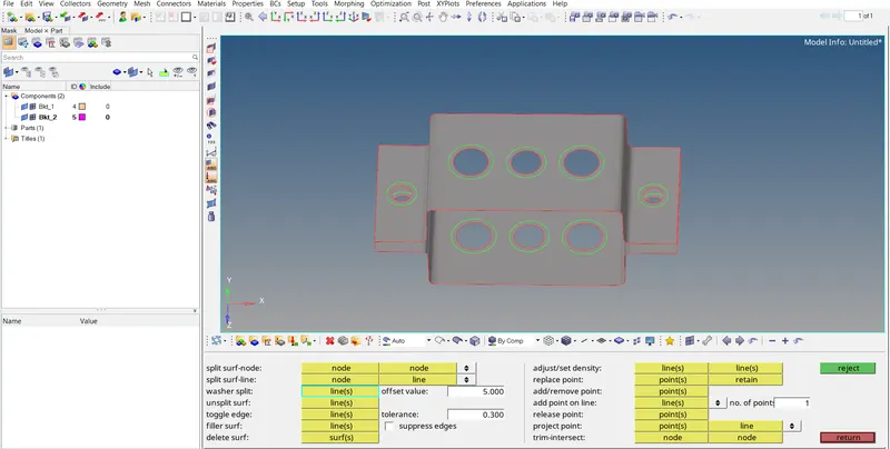
Figure1.6: Alloting the washer split for every circular geometry before mesh.
Now delete all the solids and the components except Bkt_1 and Bkt_2.
Goto => Geometry => quick edit => washer split => offeset value '5 units' => select the geometries of the circles.
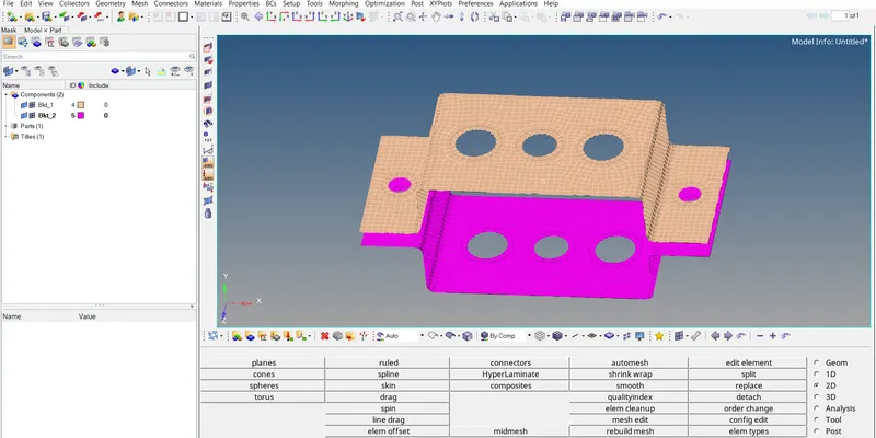
Figure1.7: 2D meshing of the components Bkt_1 and Bkt_2 .
For 2D mesh:
Goto => 2D => automesh => size and bias => surfaces => displayed => element size '5' => mesh type 'mixed' => 'mesh'
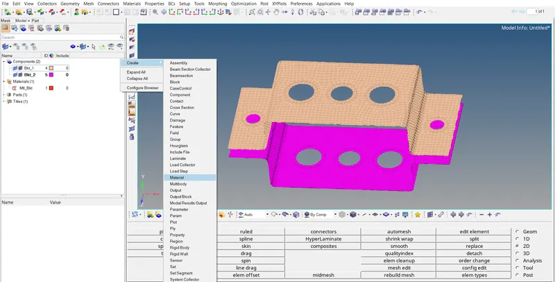
Figure1.8: Creating material 'Mtl_Bkt' for bracket-1 and bracket-2 .
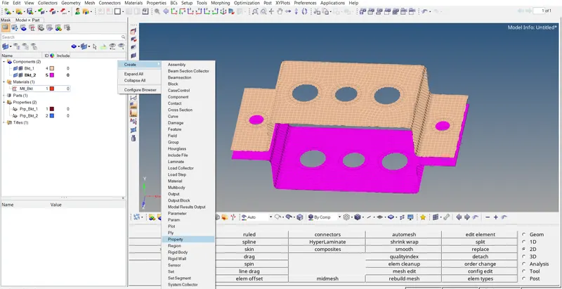
Figure1.9: Creating properties 'Prp_Bkt_1' and 'Prp_Bkt_2' for bracket-1 and bracket-2 respectively.
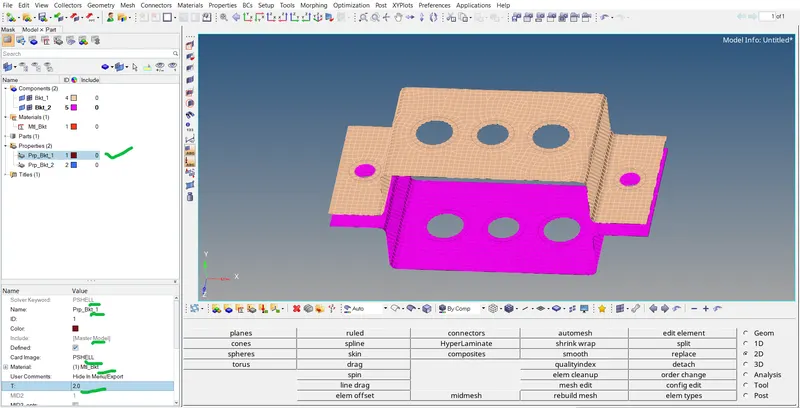
Figure1.10: Mentioning specifications to property 'Prp_Bkt_1' for bracket-1.
We are representing the 3D component with the help of shell elements therefore we are assigning the thickness of 2 units to the 'Prp_Bkt_1'.
We also assigned the 'Mtl_Bkt' to both the properties.
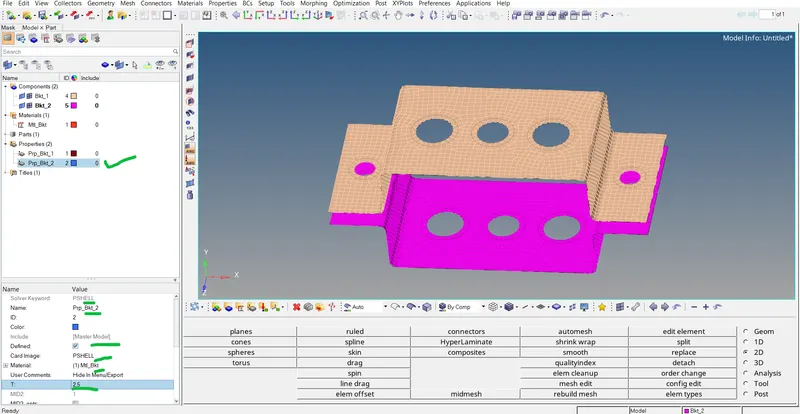
Figure1.11: Mentioning specifications to property 'Prp_Bkt_2' for bracket-2.
We are representing the 3D component with the help of shell elements therefore we are assigning the thickness of 2.5 units to the 'Prp_Bkt_2'.
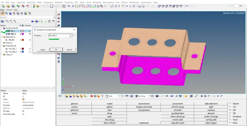
Figure1.12: Assigning the properties 'Prp_Bkt_1' and 'Prp_Bkt_2' to 'Bkt_1' and 'Bkt_2' respectively.
For assigning:
Select the component => Right click => Assign => select property => 'OK'
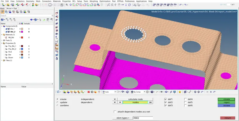
Figure1.13: Creating independent nodes using rbe2 elements.
Now we will create the independent nodes using rbe2 (rigids) and rbe3 elements at each circular geometry:
For creating rbe2 links:
Goto => 1D => rigids => create => calculate nodes => multiple nodes => select DOFs => select nodes => 'create'
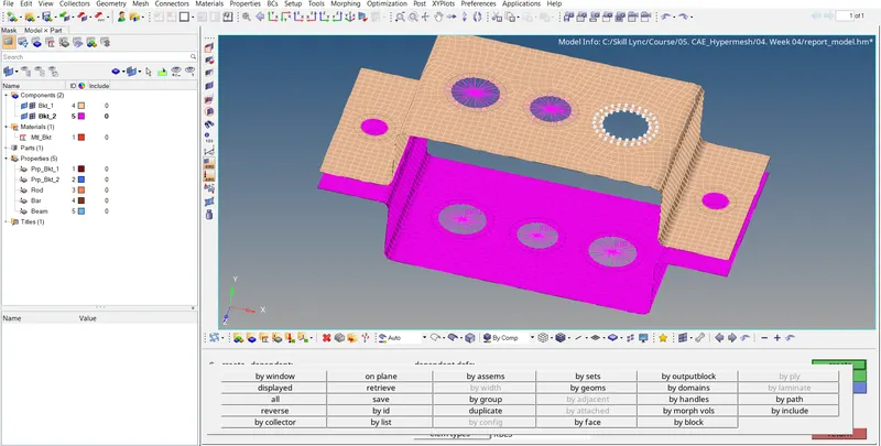
Figure1.14: Creating independent nodes using rbe3 elements.
For creating rbe3 links:
Goto => 1D => rbe3 => create => calculate nodes => nodes => by path => select DOFs => select nodes => 'create'
B].
Create 1D element of following specifications with given cross-section and DOF.
Rod element:- Translational DOF should be Constrained with RBE2 link.
Cross-Section: BOX- Dimension a= 12 mm
dimension b=10 mm
Thickness t= 0.75 mm
For creating 1D rod element:
Goto => HyperBeam => Standard sectiion => Std section library 'HYPERBEAM' => Std section type 'solid circle' => 'create'
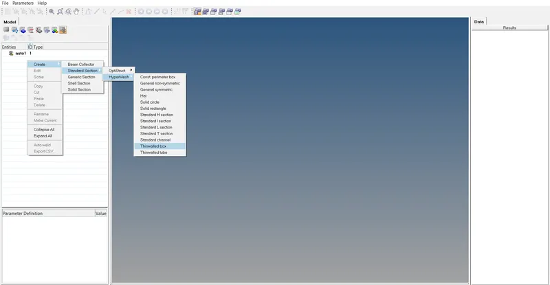
Figure2.1: Creating elements in hyperbeam view.
This will take us to the 'hyperbeam view'. Here we will create the elements as per their dimensions specified. Figure2.1 shows us how to create the elements in hyperbeam view.
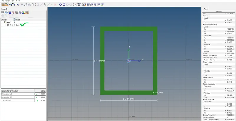
Figure2.2: Creating 1D Rod element in hyperbeam view and specifying dimensions to it.
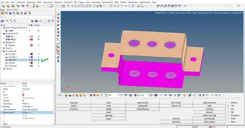
Figure2.3: Creating 'Prp_Rod' and assigning specifications to it as per 1D Rod element.
After creating the element get back to the model view.
Now create the property for the 1D Rod element and rename it as Prp_Rod and change the specifications of the property 'Prp_Rod' as per 1D Rod element.
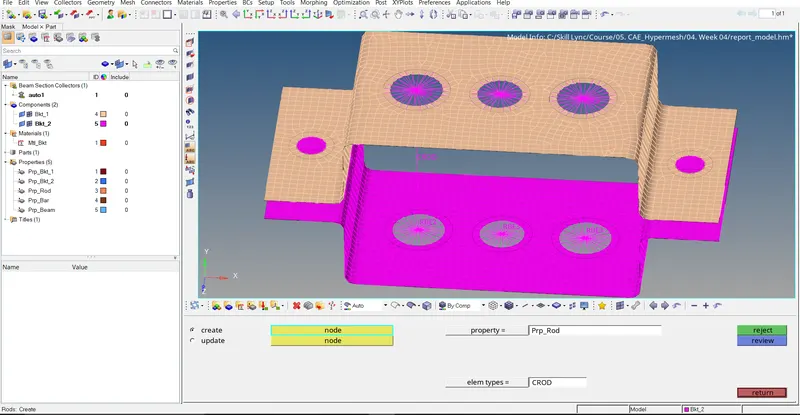
Figure2.4: Creating 1D Rod element.
For creating 1D Rod element:
Goto => 1D => rods => create => select nodes => select property => select element type => 'create'
Finally change the 1D Traditional Element Representation to '1D Detailed Element Representation'.
C].
Create 1D element of following specifications with given cross-section and DOF.
Beam element:- All DOF should be constrained with RBE3 link.
Cross-Section: I Section- Dimension a= 8 mm
Dimension b= 10 mm
Dimension c= 8.5 mm
Thickness t1= 0.75 mm
Thickness t2= .6 mm
Thickness t3= .6 mm
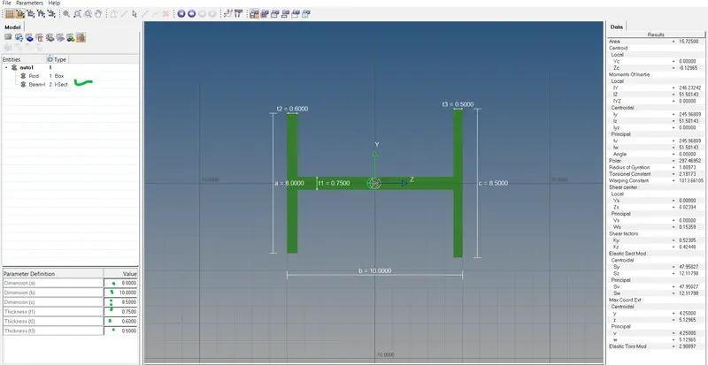
Figure3.1: Creating 1D Beam element in hyperbeam view and specifying dimensions to it.
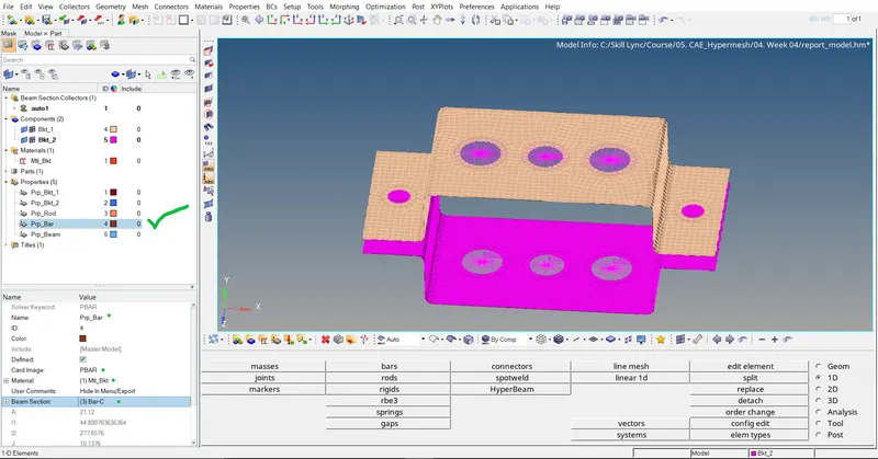
Figure3.2: Creating 'Prp_Beam' and assigning specifications to it as per 1D Beam element.
After creating the element get back to the model view.
Now create the property for the 1D Beam element and rename it as Prp_Beam and change the specifications of the property 'Prp_Beam' as per 1D Beam element.
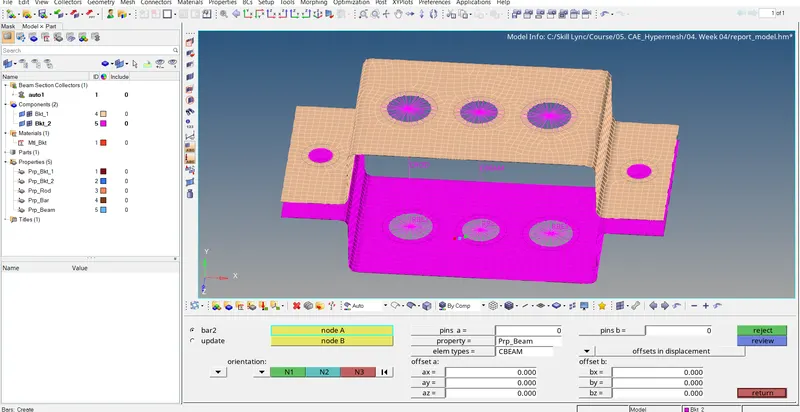
Figure3.3: Creating 1D Beam element.
For creating 1D Beam element:
Goto => 1D => bars => bar2 => select nodes => select orientation => select property => select element type => 'create'
Finally change the 1D Traditional Element Representation to '1D Detailed Element Representation'.
D].
Create 1D element of following specifications with given cross-section and DOF.
Bar element:- Constrain only X and Y DOFs With RBE3 link.
Cross-section: C section- Dimension DIM1= 5 mm
Thickness DIM2= 1.2 mm
Dimension DIM3= 10 mm
Thickness DIM4= 1.2mm
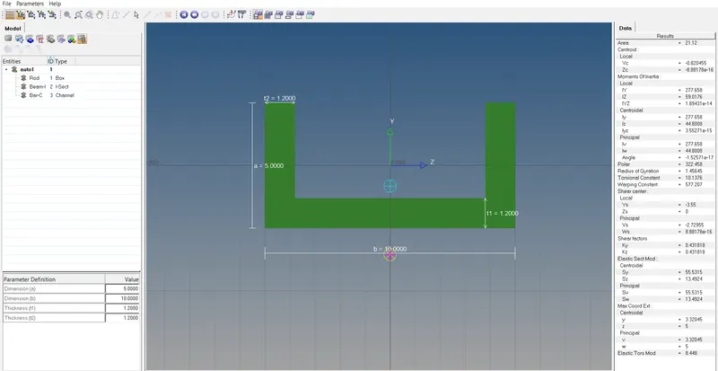
Figure4.1: Creating 1D Bar element in hyperbeam view and specifying dimensions to it.
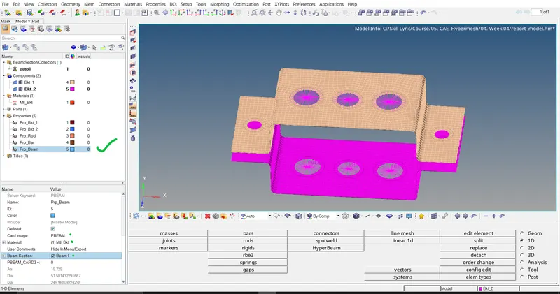
Figure4.2: Creating 'Prp_Bar' and assigning specifications to it as per 1D Bar element.
After creating the element get back to the model view.
Now create the property for the 1D Bar element and rename it as Prp_Bar and change the specifications of the property 'Prp_Bar' as per 1D Bar element.
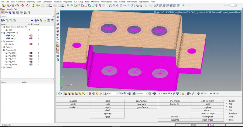
Figure4.3: Creating 1D Bar element.
For creating 1D Bar element:
Goto => 1D => bars => bar2 => select nodes => select orientation => select property => select element type => 'create'
Finally change the 1D Traditional Element Representation to '1D Detailed Element Representation'.
E].
Apply the mass of magnitude 10 with the RBE2 link.
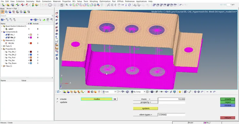
Figure5.1: Creating mass at rbe2 element.
For creating mass:
Goto => 1D => masses => create => select nodes => select mass => element type => 'create'
F].
Join the two components with Spring elements.
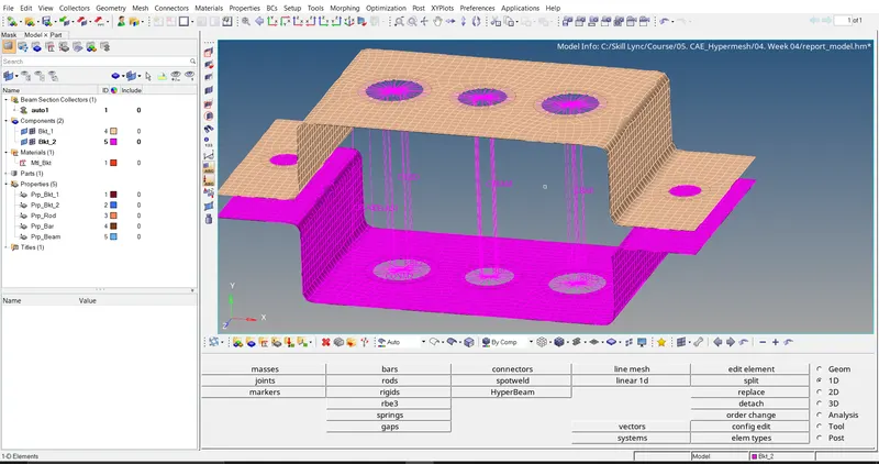
Figure6.1: Creating spring elements element.
For creating spring elements:
Goto => 1D => springs => create => select nodes => select DOFs => element type => 'create'
We can assign properties to spring and mass elements as per requirements.