Week 4-1D Element Creation Challenge
1D Element creation challenge
Objective:
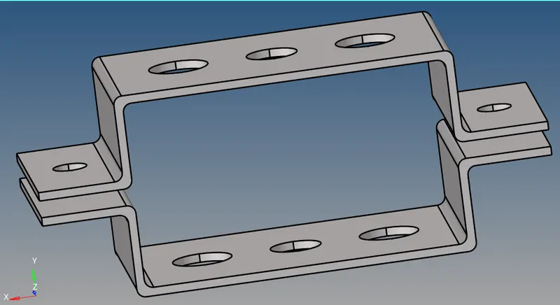
- Extract the mid surface from the given solid model parallel bracket.
- To mesh the parallel bracket component of element size as 5 units.
- To create 1d elements like rod element,beam element and bar element for given cross section of box,I section and X section
- Rod element:- Translational DOF should be Constrained with RBE2 link
Cross-Section: BOX- Dimension a= 12 mm
dimension b=10 mm
Thickness t= 0.75 mm
- Beam element:- All DOF should be constrained with RBE3 link
Cross-Section: I Section- Dimension a= 8 mm
Dimension b= 10 mm
Dimension c= 8.5 mm
Thickness t1= 0.75 mm
Thickness t2= .6 mm
Thickness t3= .6 mm
- Bar element:- Constraint only x and y DOFs With RBE3 link
Cross-section: X section- Dimension DIM1= 5 mm
Thickness DIM2= 1.2 mm
Dimension DIM3= 10 mm
Thickness DIM4= 1.2mm
- & e. Apply the mass of magnitude 10 with the RBE2 link
- Join the two components with Spring elements
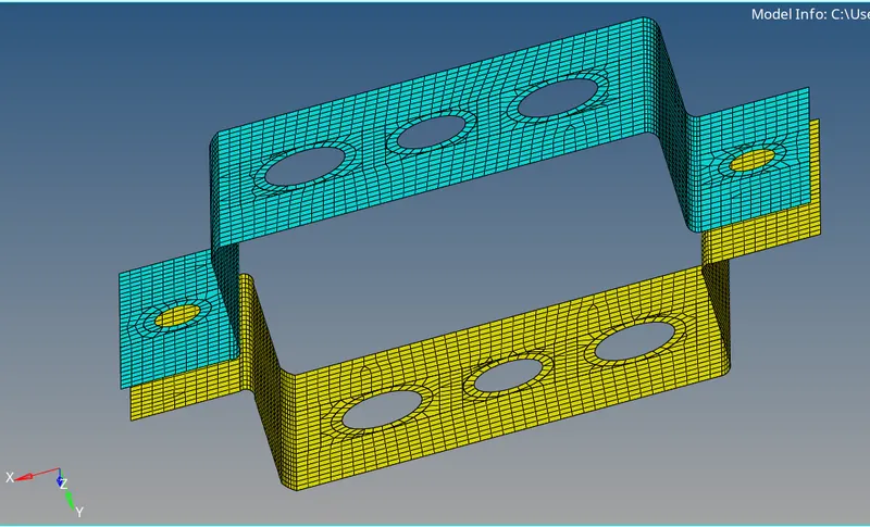
1.Extract the mid surface from the given solid model parallel bracket.
Procedure:
- Import the given model by choosing the IGES file type.
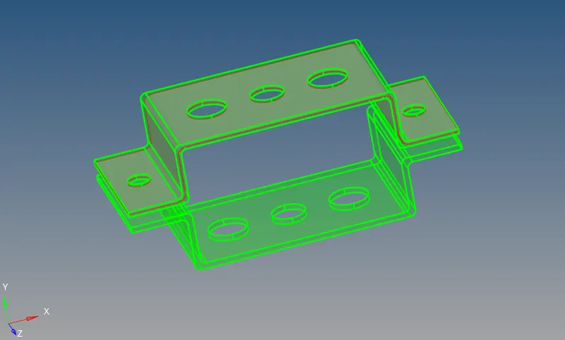
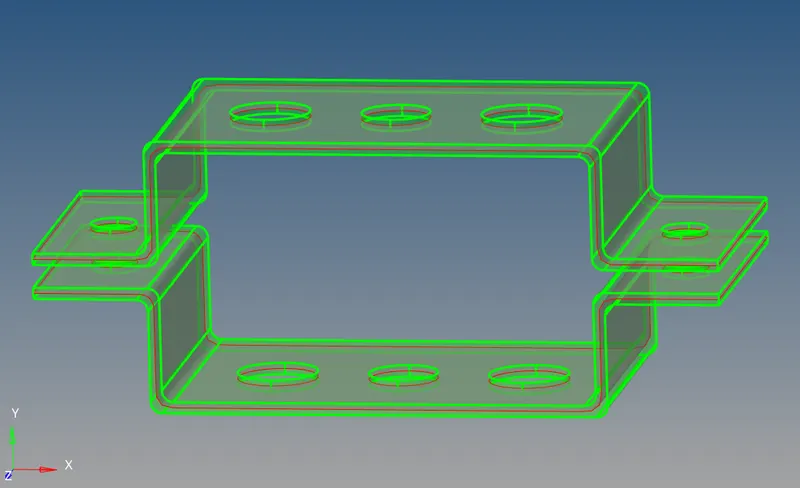
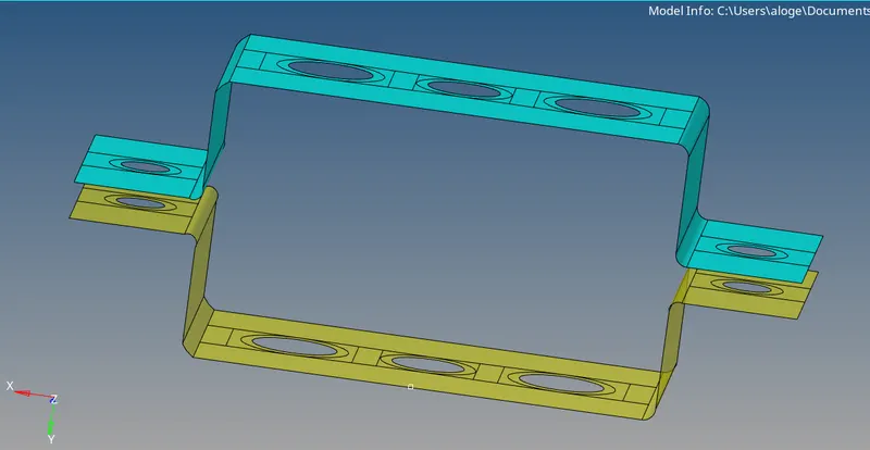
- By using the mid surface —> auto extracting —>select the displayed surface—-> extract the midsurface.
- After extracting the mid surface make the geometry clean up by using the autoclean up —-> displayed surface.
Images
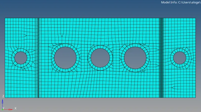
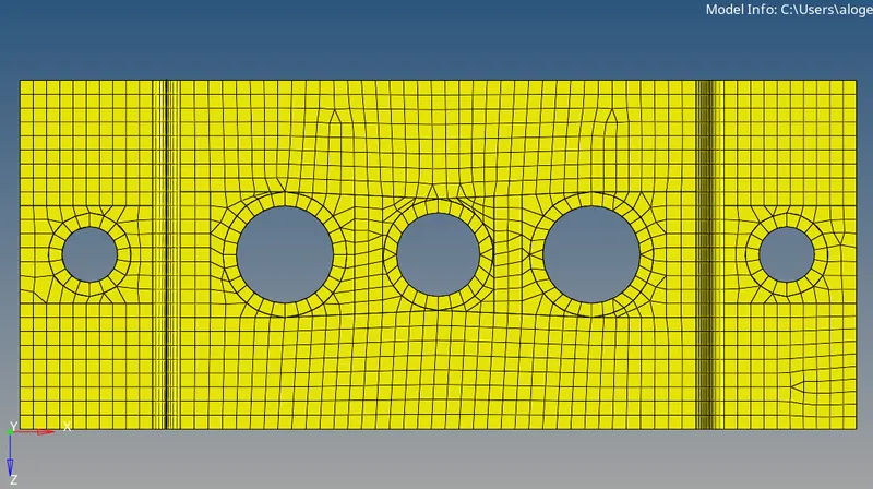
2.To mesh the parallel bracket component of element size as 5 units.
Procedure:
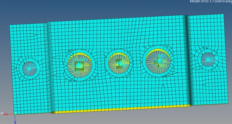
- By using 2d —> automesh —> select the displayed surface —> select the element size as 5 units with mixed elements and mesh the given components.
- By using a quick edit tool to make proper mesh.
Images,
3.To create 1d elements like rod element,beam element and bar element for given cross section of box,I section and X section
Procedure:
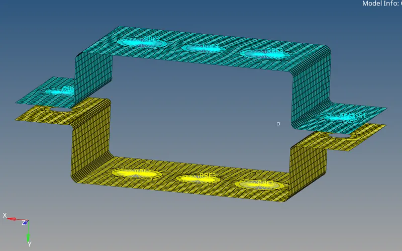
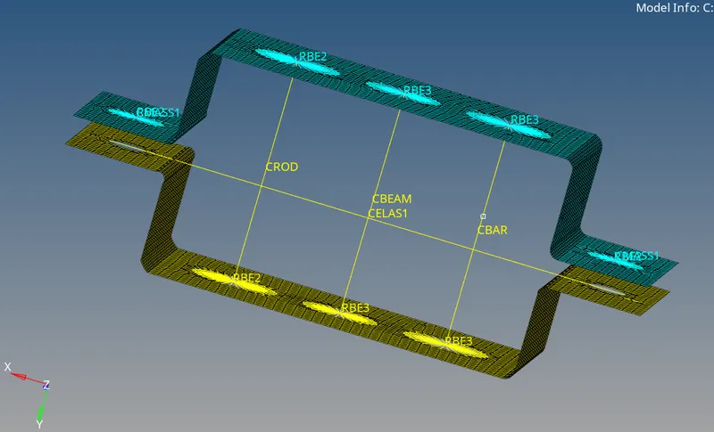
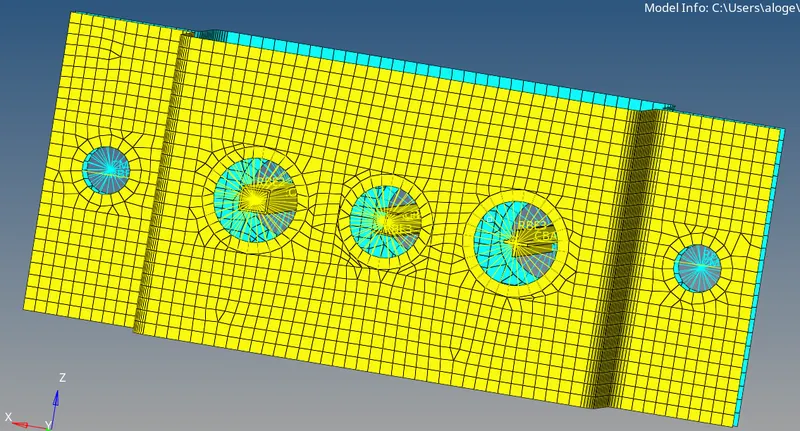
- By using 1d --->create RBE2 links in section A-A by selecting --->Rigid--->create--->selecting the nodes by path and select the DOF as per requirement and create the links.
- By using 1d ---> create RBE3 links in section B-B by selecting --->RBE3--->create--->selecting the nodes bypath and select the DOF as per requirement and create the links.
- By using 1d ---> create RBE3 links in section C-C by selecting --->RBE3--->create--->selecting the nodes bypath and select the DOF as per requirement and create the links.
- By using 1d ---> create RBE2 links in section C-C by selecting --->RBE3--->create--->selecting the nodes bypath and select the DOF as per requirement and create the links.
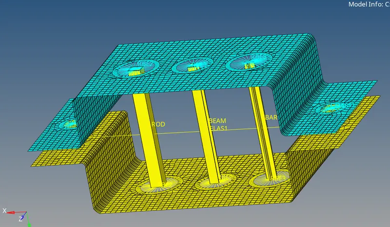
- By using 1d ---> create bars,rod and beams as per the links assign to the links.
- By using 1d ---> hyperbeams---> standard section---> hypermesh--->thinwalled box ---> give the dimensions as per requirement
- By using 1d ---> hyperbeams---> standard section---> hypermesh--->I section---> give the dimensions as per requirement
- By using 1d ---> hyperbeams---> standard section---> Optistruct--->Cross section---> give the dimensions as per requirement
- After creating the cross section assign the property and assign the coressponding Elements.
- By using 1d ---> spring---> choose the nodes ---> element type--->CELSE1 for section F-F
- By using 1d ---> masses ---> choose the nodes ---> element type--->CMASS1.
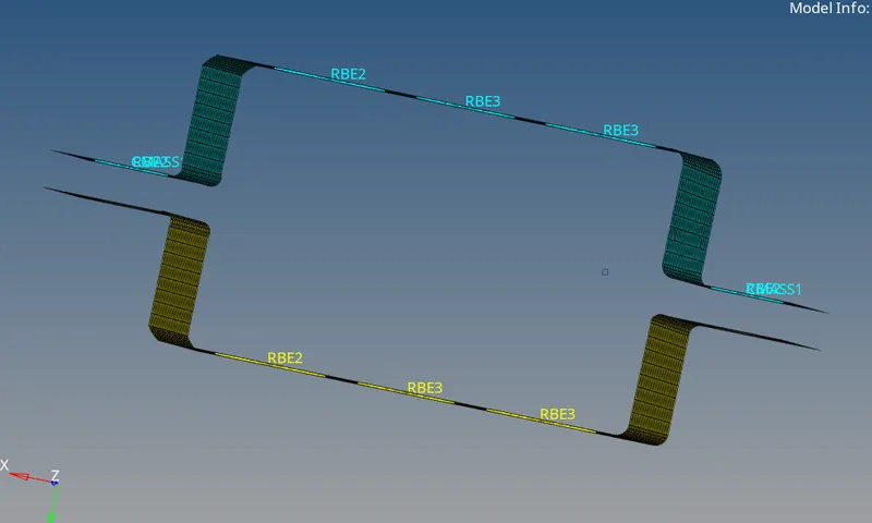
Images,
Conclusion,
- Thus the mid surface is extracted from the given solid component
- Also mesh is carried out for the extracted midsurface
- Then the links & elements are created for the cross section with corresponding DOFs.