Week 4-1D Element Creation Challenge
Objective:
The objective is to mesh the component with given mesh size and also creating 1d elements on the component with given cross-sections and DOF's.
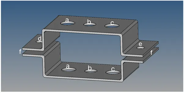
CAD model image:
Procedure:
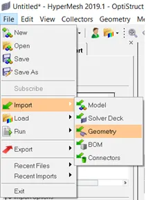
First click on File option on menu bar. And then click on import option and select import geometry option.
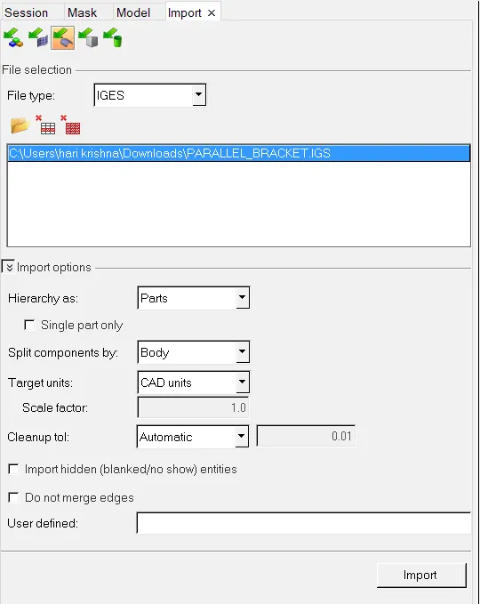
Select file type as IGES, since the given the model is in .igs format. And select file and click on import.
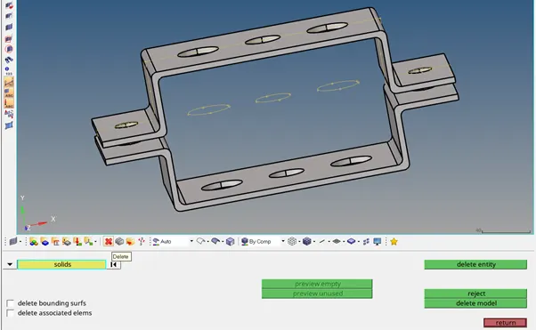
After importing the model in hypermesh it will be in wireframe mode so we to convert it into shaded view.Now click on delete- select solids option and click on all to select entire model. And click on delete entity to delete all the solids in GUI.
Before creating a midsurface, make a habit of creating a component. So now click the right mouse button near components in entities tab
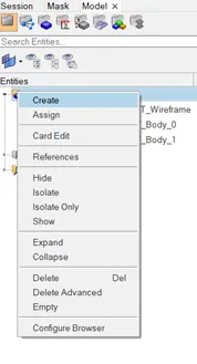
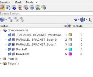
And click on create when the dialog box appears. And create the components. Here 2 components, namely bracket1 and bracket2 are created.
Now go to Goem>midsurface>and select surface and click extract to create a midsurface.

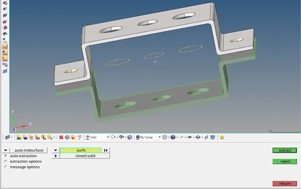
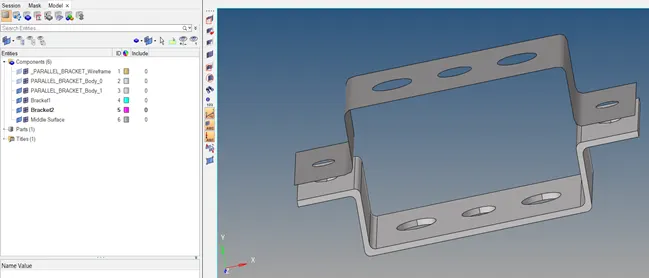
Now go tools>organize.

Choose collectors option and select the dest. component i.e. desired component to be moved as current component and click on surface and after that click on move.
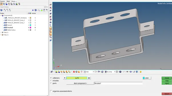
And now delete midsurface in components list.
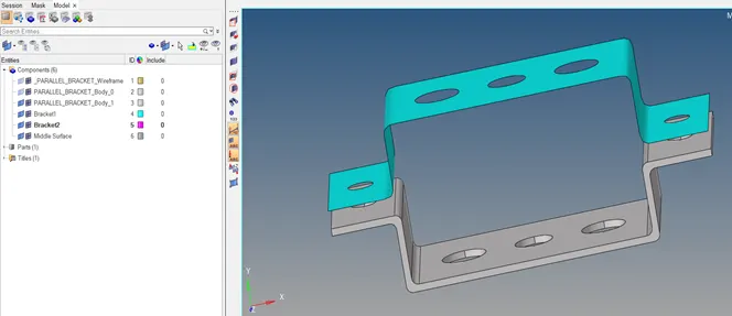
Now create the midsurface on the bottom bracket and follow the similar steps used in creating a midsurface for top bracket.
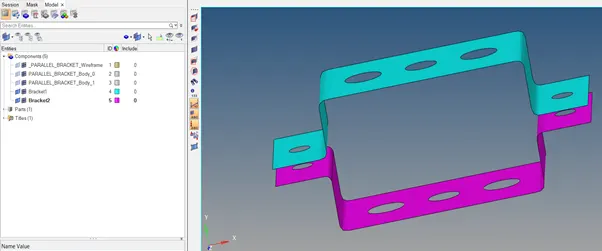
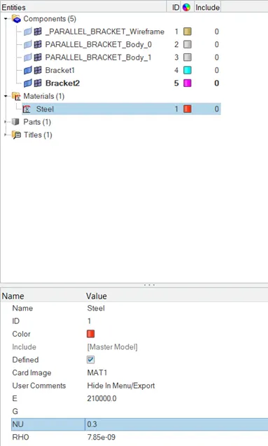
Midsurface is a 2D representation of 3D component. So how it will be a 3D if we don’t assign a thickness to the model. So that first we need we need to assign a material for the model. To assign a material to model, for that click on right mouse button in entities tab and click on create and select material option.
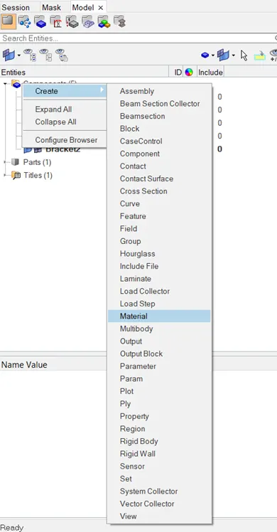
And then rename it as steel. Select the required card image or we can also call it as card id according to the material we have chosen. Click on parameters under the materials tab and select the required parameters young’s modulus E, poisson’s ratio NU and density RHO and press enter.
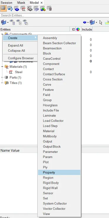
Now we need assign a property. For that click on right mouse button in entities tab and click on create and select property. Create 2 properties.
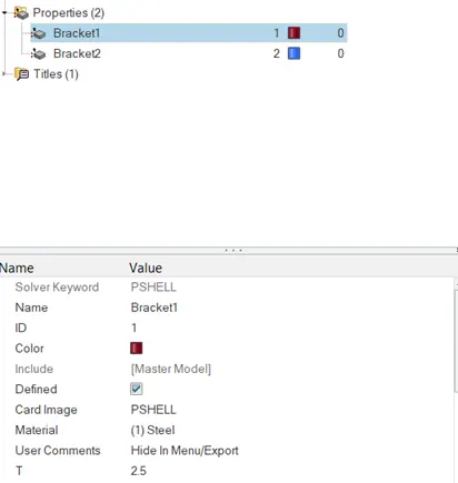
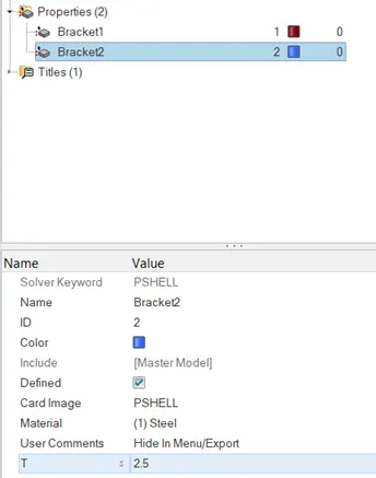
And rename them. The reason for creating 2 properties is that have 2 midsurfaces and also we can define different thickness for the two midsurfaces which we created. Click on property and in property tab make sure that card id is in PSHELL, assign material as steel and enter thickness T value and press enter and repeat the same for the other property too i.e. for bracket2.
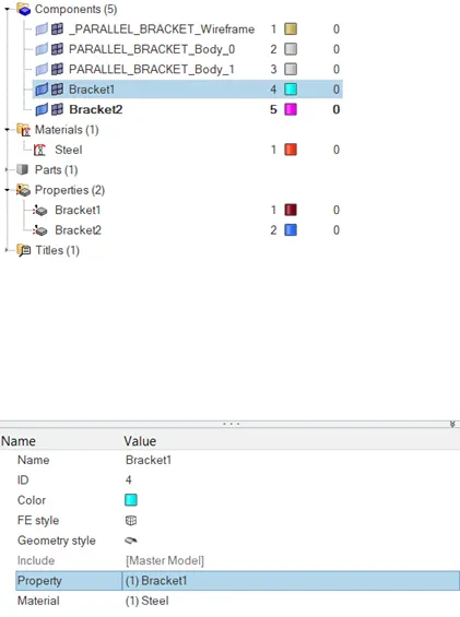
After that assign the created property to components.
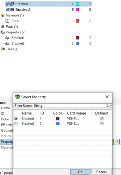
So click on bracket1 in components list and now click on property and assign the created property for bracket1.
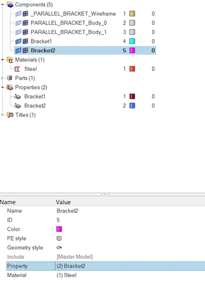
Similarly repeat the same for other component i.e. for bracket2.
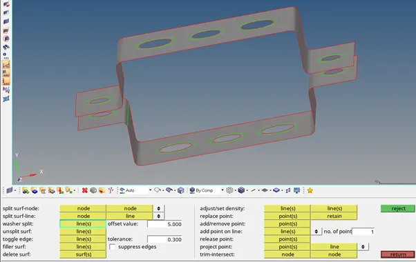
Now go to quick edit in geom to create washer split for the model. In offset value type the required distance for example 5mm is taken for this model. Click on lines where the offset required.
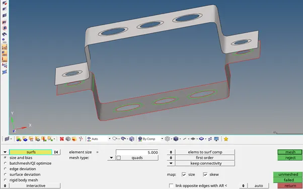
Now go to 2d section and click on automesh option.

Click on surfs and select top bracket suface. Now type element size as 5 and mesh type as quads. Now click on mesh.
Now make some element adjustments in the model near the washer split. By left mouse click we can increase the number of nodes and decrease using right mouse click.
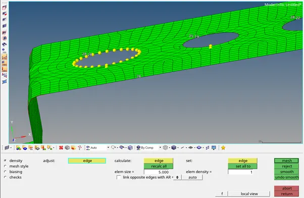
click on mesh option and return.
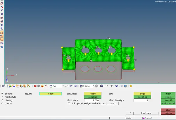
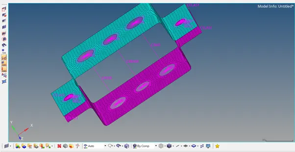
Now repeat the same for bottom bracket. Final mesh of brackets is shown in figure below.
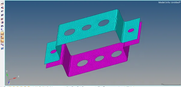
Now we need to create 1d elements for the given model with given cross section and DOF’s. So for the given component at 'a' location we need to create Rod element by taking translational DOF’s as the constraint with RBE2 LINK. So first create RBE2 link at location 'a'.Now go to 1d>rigids>calculate nodes>Multiple nodes>click on nodes and Select nodes by path, and click mouse on the model to create nodes near the circle.
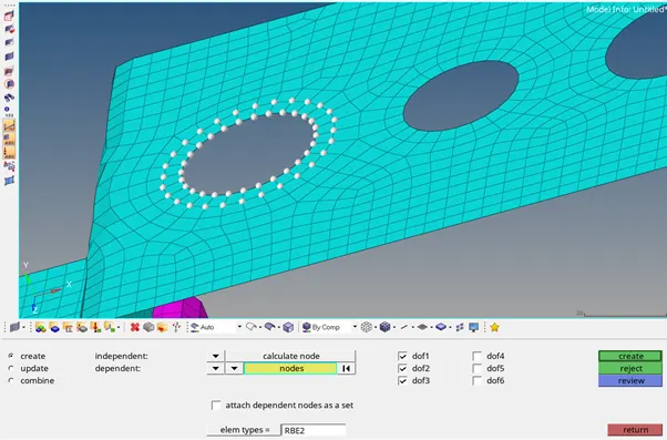
Now see the constraints given for that hole and untick the DOF's not required.And click on create to create the RBE2 link.
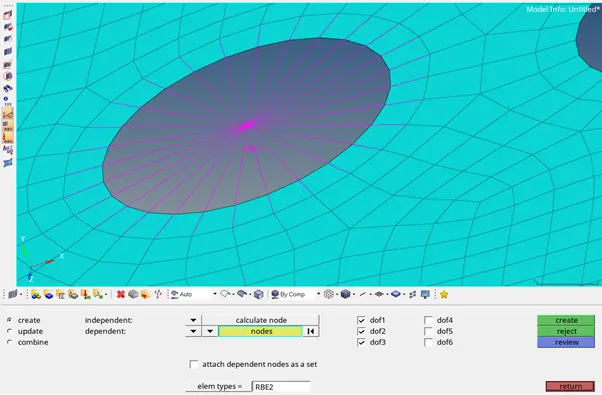
Repeat the same for bottom bracket at location 'a'.
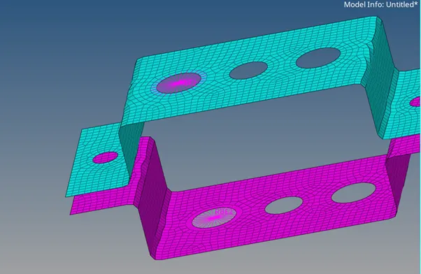
Now we need create a beam element with RBE3 link by taking all constraints into consideration at location ‘b’. so go to 1d>rbe3>click on nodes and Select nodes by path,click mouse on the model to create nodes near the circle.
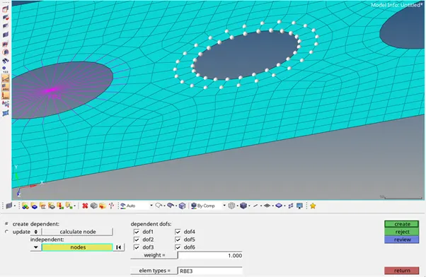
now see the constraints given for that hole and untick the DOF's not required and and click on create to create the RBE3 link. And repeat the same for bottom bracket.
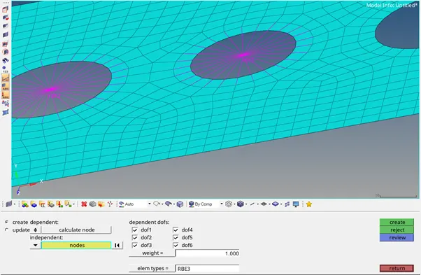
Now we need create a bar element with RBE3 link by taking only x and y constraints into consideration at location ‘c’. So go to 1d>rbe3>click on nodes and Select nodes by path,click mouse on the model to create nodes near the circle.
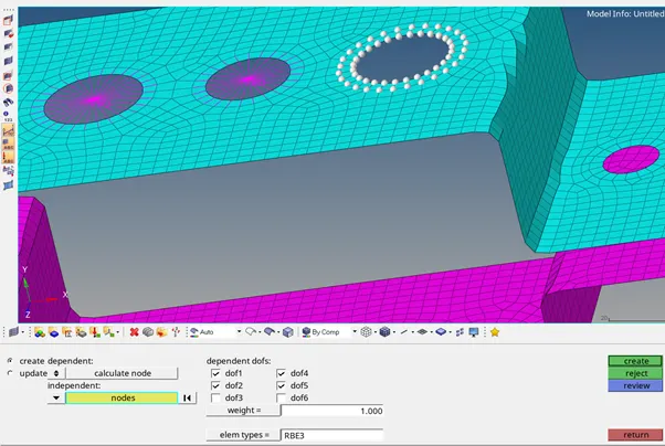
now see the constraints given for that hole and untick the DOF's not required and and click on create to create the RBE3 link. And repeat the same for bottom bracket.
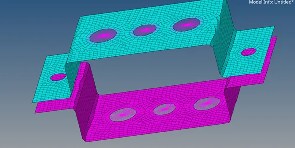
After creating the RBE2 and RBE3 links at the locations 'a', 'b' and 'c'. Now we need to create the elements. So go to 1d> rods> select create option and select element type as CROD.click on node and select the node on top bracket and click on node and select the node on bottom bracket at location 'a' on RBE2 links. After CROD element is created,click on return.
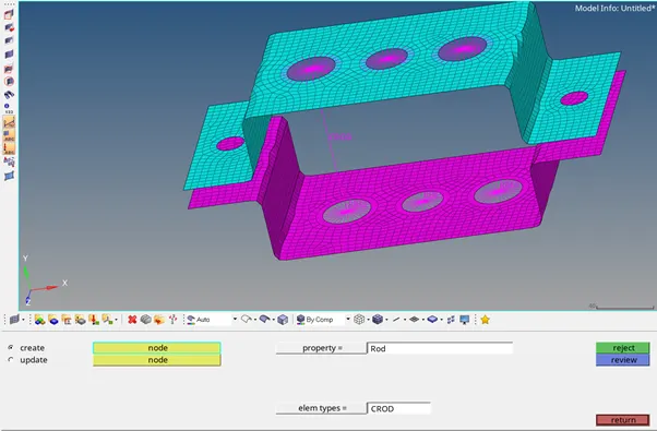
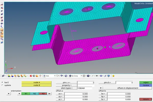
Now go to 1d> bars> select bar2 option and select element type as CBEAM.click on node A and select the node on top bracket and click on node B and select the node on bottom bracket at location 'b' on RBE3 links. Set the orientation i.e. N1 & N2 and press tab to create the element, after that click on return.
Now go to 1d> bars> select bar2 option and select element type as CBAR.click on node A and select the node on top bracket and click on node B and select the node on bottom bracket at location 'b' on RBE3 links. Set the orientation i.e. N1 & N2. 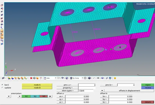
press on tab to create the element, after that click on return.
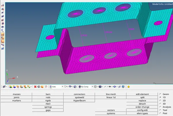
So for each element in the model a cross-section is defined to it. So for example, rod element have box cross-section. Therefore,so for each element a different cross-section is defined.
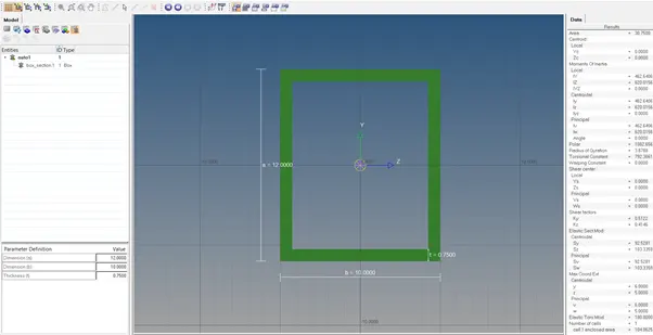
Now go to 1d>Hyperbeam> select standard section> under standard section library> select hyper beam> under standard section type >select thin walled box and click on create.

Now hyperbeam window appears. And type the box dimension values.
Dimension a= 12 mm
dimension b=10 mm
Thickness t= 0.75 mm
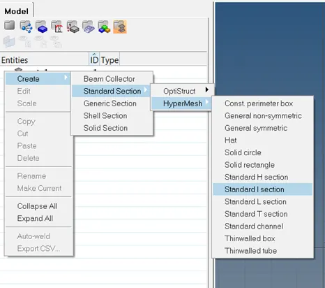
Now we need to create the cross-section for beam element.For that we can create it on hyperbeam window. click the right mouse button in the entities tab and go to create>Standard section>hypermesh> standard I section.
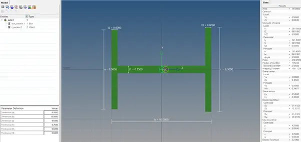
Now enter the parameters for I-section.
Dimension a= 8 mm
Dimension b= 10 mm
Dimension c= 8.5 mm
Thickness t1= 0.75 mm
Thickness t2= .6 mm
Thickness t3= .6 mm
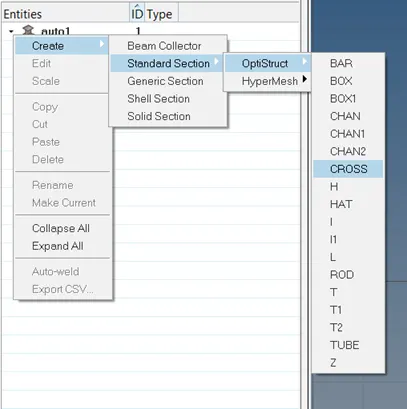
Now we need to create the cross-section for bar element. Now click the right mouse button in the entities tab and go to create>Standard section>optistruct>CROSS.
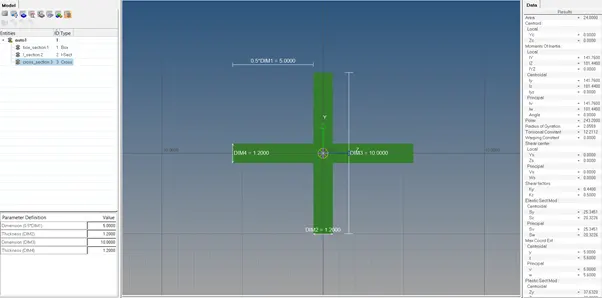
Now enter the parameters for X-section.
Dimension DIM1= 5 mm
Thickness DIM2= 1.2 mm
Dimension DIM3= 10 mm
Thickness DIM4= 1.2mm
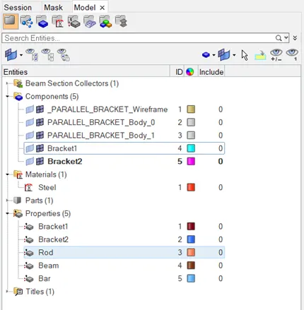
Now return to model window and create 3 propeties in property tab. Click right mouse button in properties tab and select create option and create 3 properties. Now rename them as rod, beam and bar.
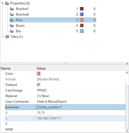
Now in properties,click on rod and change card image to PROD. After that click on material to assign the material. Now click on beamsec and select box_section1.
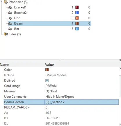
Now in properties, click on beam and change card image to PBEAM. After that click on material to assign the material. Now click on beam section and select I_section2.
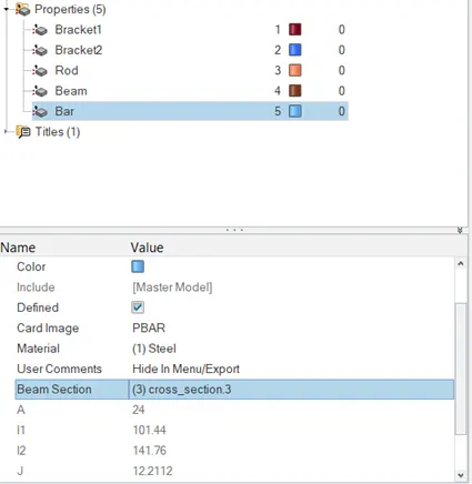
Now in properties, click on bar and change card image to PBAR. After that click on material to assign the material. Now click on beam section and select Cross_section3.
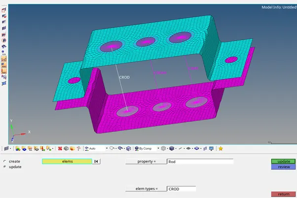
Now go to 1d>rods> select update option and under property select as Rod, now click on CROD element in the model and click on update.
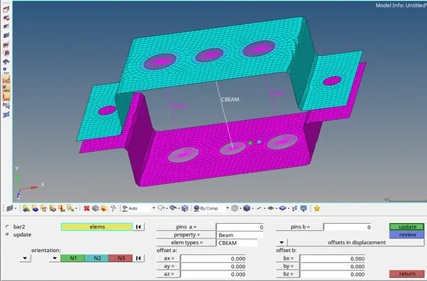
Now go to 1d>bars> select update option and under property select as Beam, now click on elems and select CBEAM element in the model,after that set the orientation i.e. N1 and N2. Now click on update.
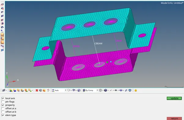
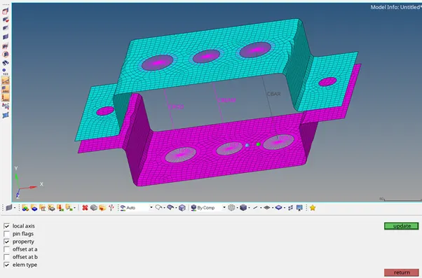
Now select local axis, property and elem type and click on update to update these parameters.
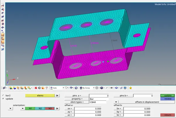
Now go to 1d>bars> select update option and under property select as Bar, now click on elems and select CBAR element in the model,after that set the orientation i.e. N1 and N2. Now click on update.
Now select local axis, property and elem type and click on update to update these parameters.
So for the given component at locations 'd' & 'e' we need to apply mass with RBE2 LINK. So first create RBE2 link at location 'd'.Now go to 1d>rigids>calculate nodes>Multiple nodes>click on nodes and Select nodes by path, and click mouse on the model to create nodes near the circle at location 'd' of top bracket.And click on create to create the RBE2 link.
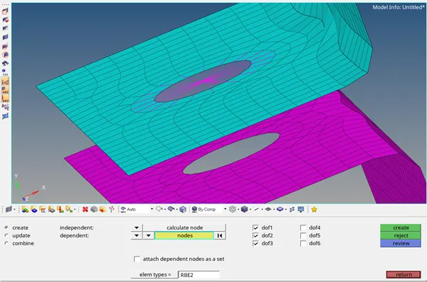
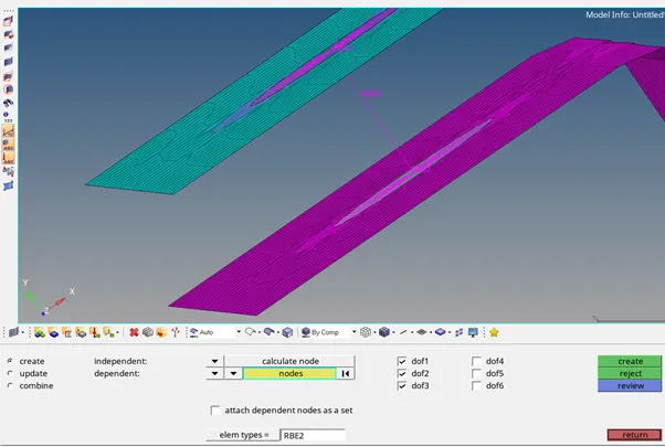
Repeat the same for bottom bracket at location 'd'. Now join top & bottom bracket with RBE2 link.
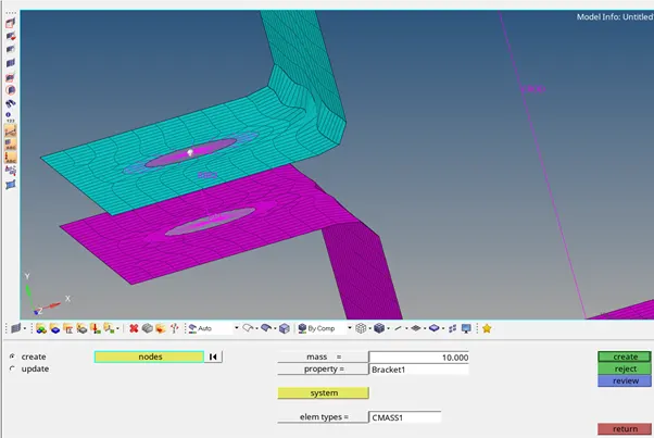
Now go to 1d>masses, select create option, click on nodes and select node at location 'd' on RBE2 link of top bracket. Now enter mass=10.000. and elem types= CMASS1 and click on create to create mass. Repeat the same process for location 'e' of the model.
Now we need to join the components with spring elements at location 'f' on both the sides of model. For that go to 1d>springs> elem types= CELAS1. select required DOF's and click on node and select the node on top bracket and click on node and select the node on bottom bracket at location 'f' .
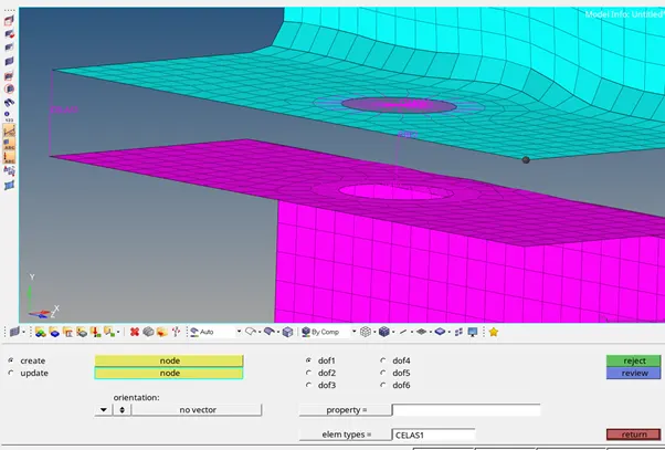
After spring is created, now click on return. Repeat the same process on other side of bracket at location 'f'.
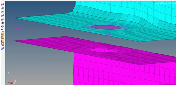
Final CAD model:
Conlusions:
Thus by creating this bracket in hypermesh we get some familiarisation of tools like creating a misurface in the geometry section, meshing of a components using 2d and creating 1d elements like rods, bars, beams, masses and spring on the component with given cross-sections and DOF's.