Week 4-1D Element Creation Challenge
Q1.
Objective:
Mesh the Given component with the Size of 5 Units. Create 1D elements on the following component with given cross-section and DOF
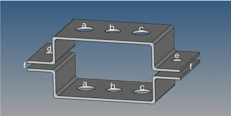
CAD Model Image:
Procedure with required Images:
Step 1
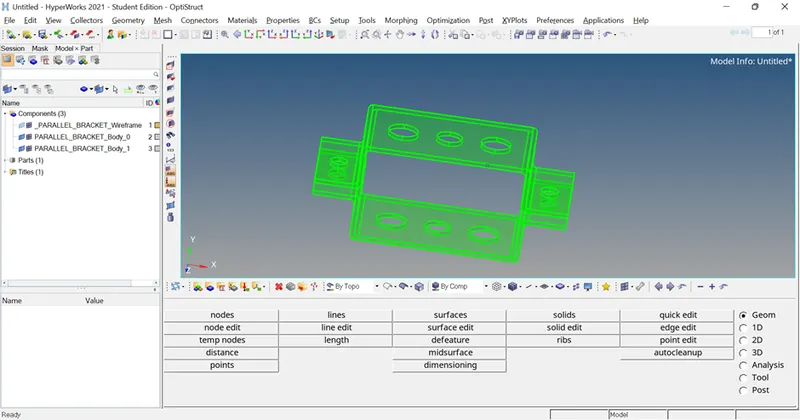
Geometry was imported into Hyperworks graphics area.
Step 2
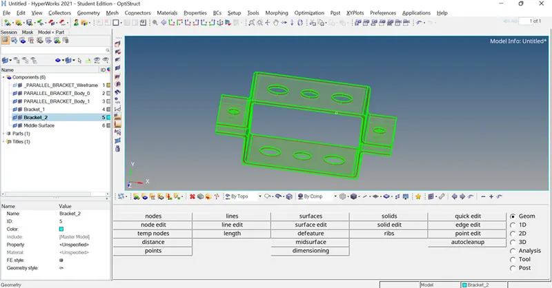
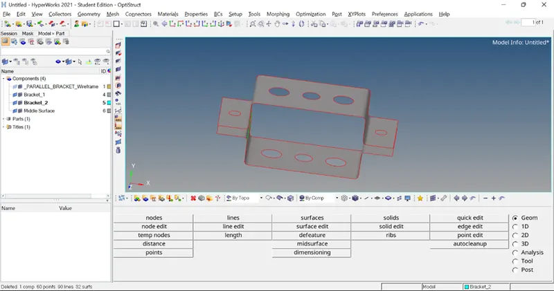
Midsurfaces were created individually in each bracket component. After that solid parts were deleted.
Step 3
Material of steel was created.
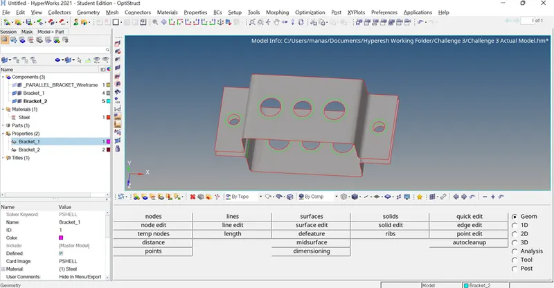
Property for each bracket was created and it was assigned to respective bracket.
Step 4:
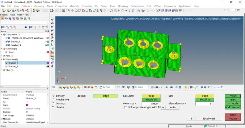
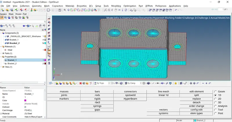
Washer split was applied at each hole. Then 2d Mesh was done with element size of 5 of mixed type.
Step 5
The following Elements were created with mentioned DOF.
At point A – RBE2 link with Translational DOF constrained and Rod element was created
At point B – RBE3 link with all DOF constrained and Beam element was created
At point C – RBE3 link with X and Y directions DOF constrained and Bar element was created
Then by going to Hyperbeam pagefollowing cross section were created with the given dimension.
- Rod element:- Translational DOF should be Constrained with RBE2 link
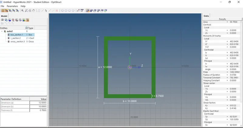
Cross-Section: BOX- Dimension a= 12 mm
dimension b=10 mm
Thickness t= 0.75 mm
- Beam element:- All DOF should be constrained with RBE3 link
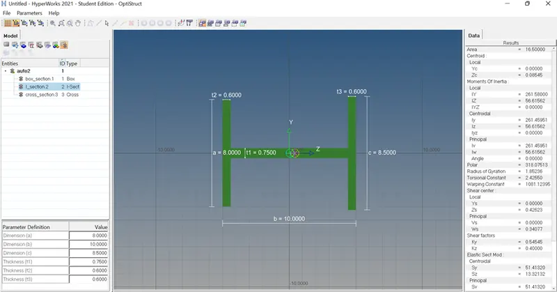
Cross-Section: I Section- Dimension a= 8 mm
Dimension b= 10 mm
Dimension c= 8.5 mm
Thickness t1= 0.75 mm
Thickness t2= .6 mm
Thickness t3= .6 mm
- Bar element:- Constrain only xand y DOFs With RBE3 link
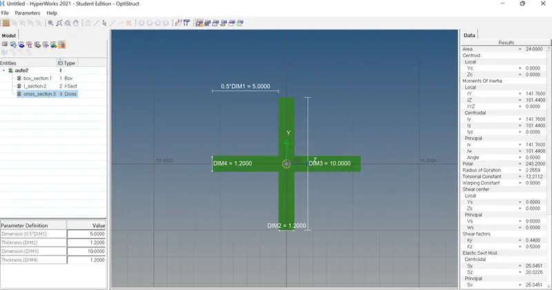
Cross-section: X section- Dimension DIM1= 5 mm
Thickness DIM2= 1.2 mm
Dimension DIM3= 10 mm
Thickness DIM4= 1.2mm
Step 6
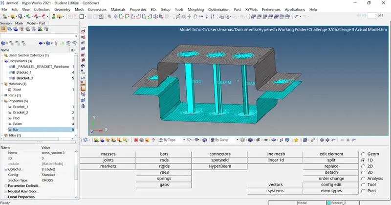
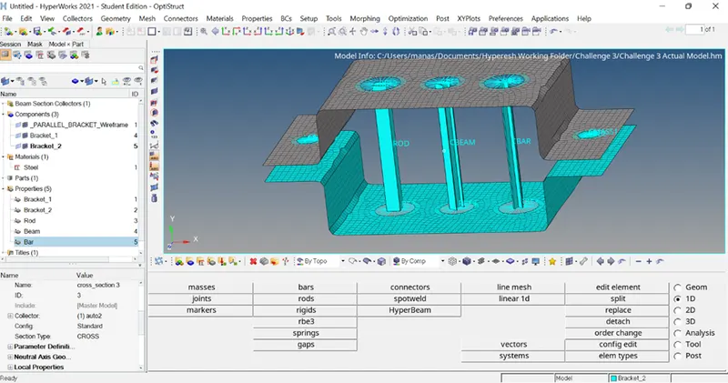
Rod, Bar and Beam elements were created at given place.
Property for each Rod, bar and Beam were created and assigned to respective element.
Step 7
At point D and E mass of magnitude 10 with RBE2 link was created.
At point F spring element was created.
Results and Final Model Image: