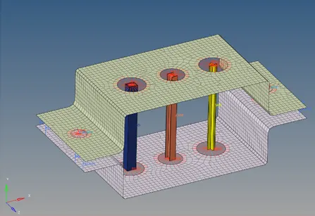
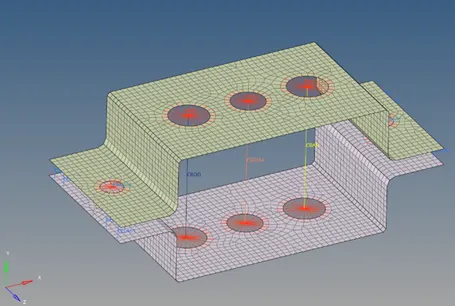
Week 4-1D Element Creation Challenge
Objective: Mesh the given component with the size of 5 units and create 1D elements on the following component with given cross-section and DOF
Procedure:
- Open HyperMesh and set user profile as Optistruct
- Import the geometry (.IGS) into Hypermesh
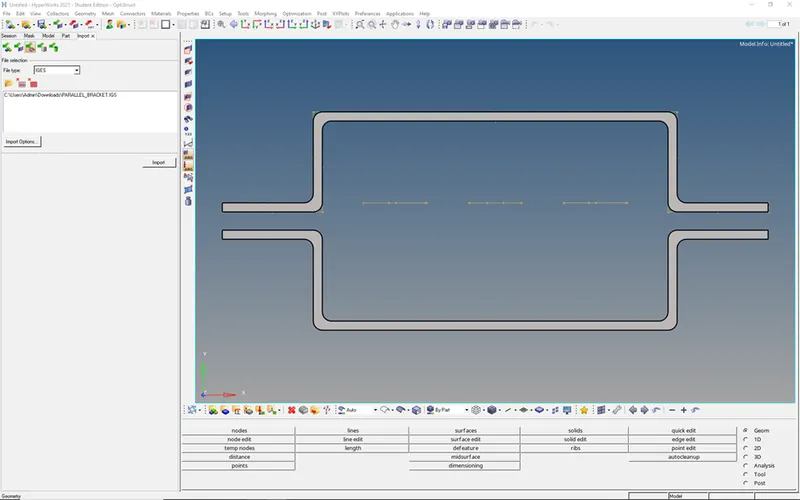
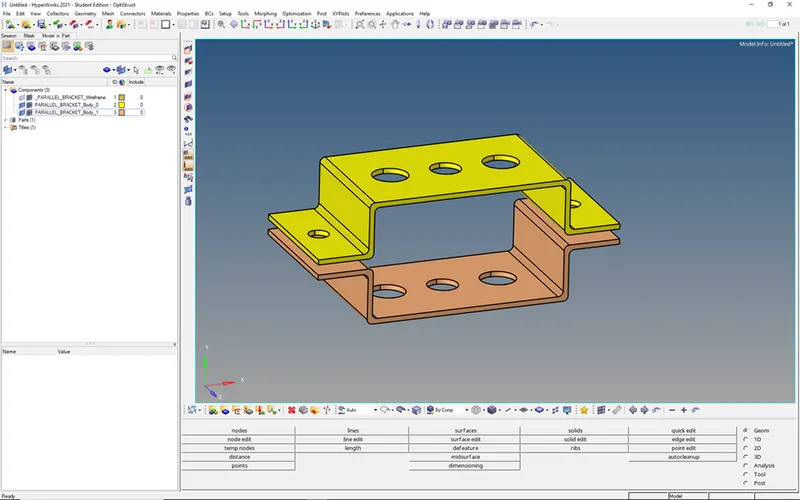
- Here I hide the lines component and change the color of the other two components for visualization purpose
- Extract the mid surface of the model, as this is constant thickness throughout so go with auto mid surface extraction (geometry -> mid surface)
- Create two more components (Mid surface_body_0 & Mid surface_body_1) for mid surfaces
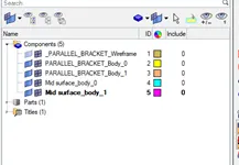
- Before extracting, change the result into the current component in extraction options then extract the particular body
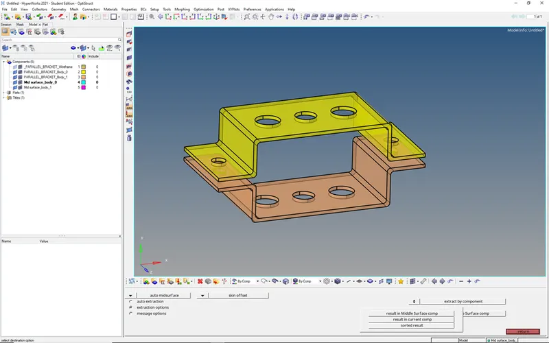
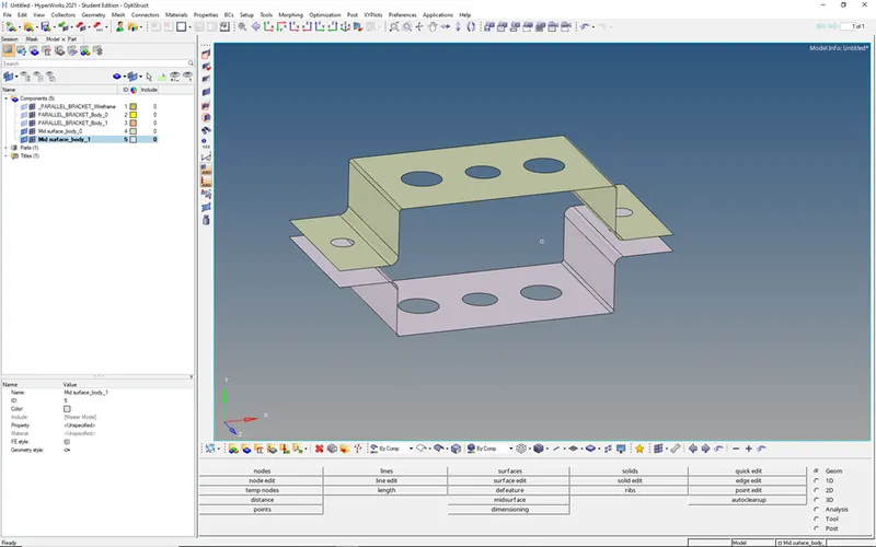
- After extracting and hiding the solid geometry it looks like this
- Add a washer split of 5 units to the holes
- Geometry -> Quick edit -> washer split -> select the lines (offset value: 5 units)
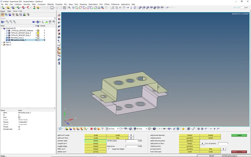
- Now your component is ready for mesh
- Press F12 -> select the particular component surfaces and mesh with an element size of 5 units in the particular component
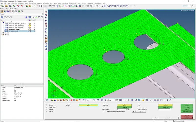
- Remove trias in washer areas
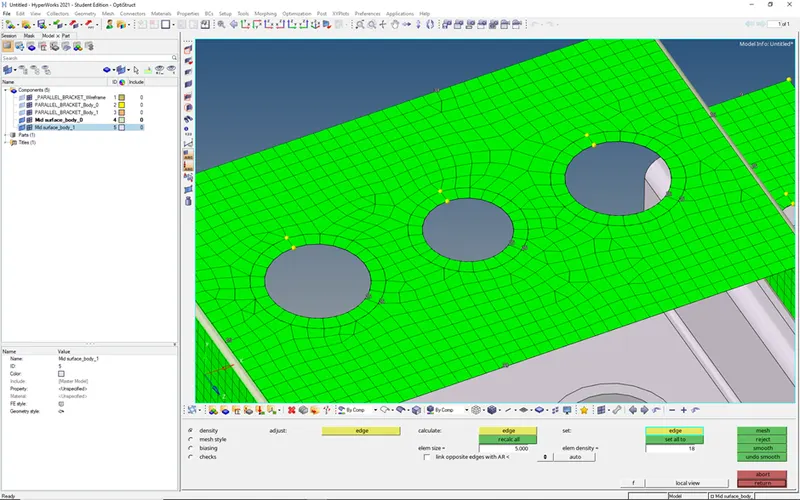
- Check any trias is there in fillet region or not
- If not mesh the other component
- After completing the meshing to both the components, it look like this
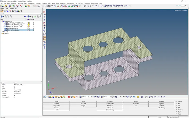
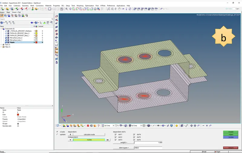
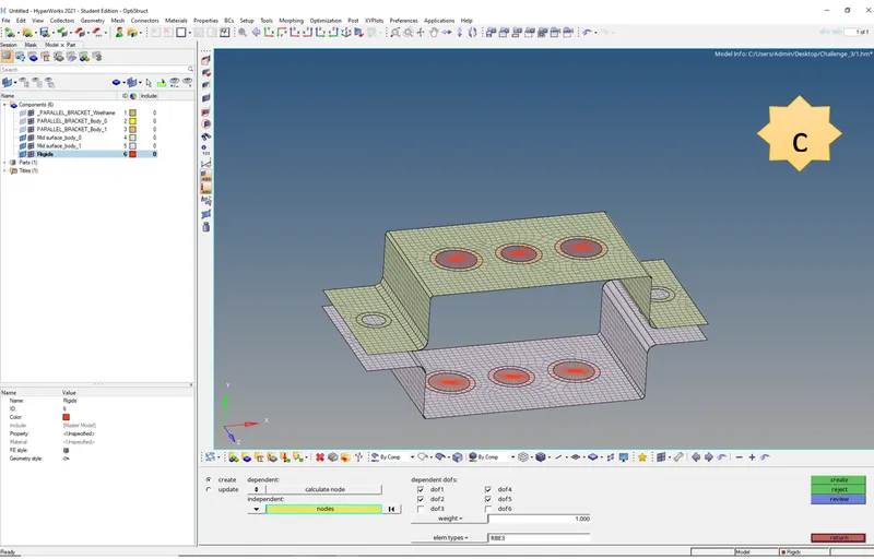
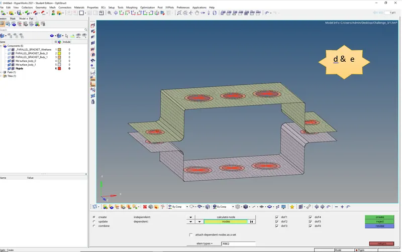
- Now we need to add rigid elements at the areas (a,b,c,d,e,f) with different DOF’s and 1D Elements
|
Position |
Constraints |
Element |
|
|
Type |
Cross sectional area |
||
|
a |
Translational DOF should be Constrained with RBE2 link |
Rod Element |
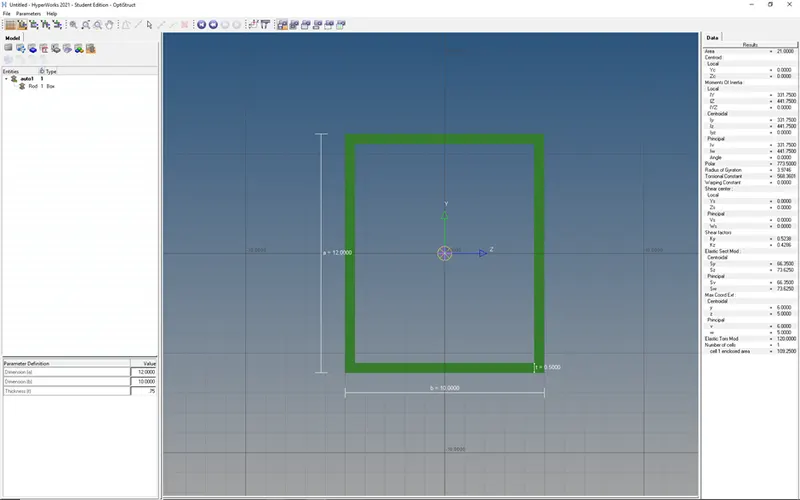
Box: a= 12 mm,b = 10 mm,t = 0.75 mm |
|
b |
All DOF should be constrained with RBE3 link |
Beam Element |
I Section: a= 8 mm, b= 10 mm, c= 8.5 mm, t1= 0.75 mm, t2= 0.6 mm, t3=0.6 mm |
|
c |
Constrain only x and y DOFs With RBE3 link |
Bar Element |
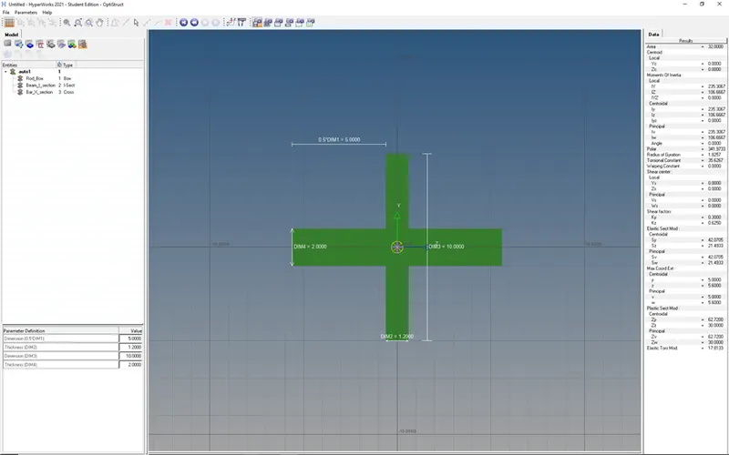
X section: Dimension DIM1= 5 mm Thickness DIM2= 1.2 mm Dimension DIM3= 10 mm Thickness DIM4= 1.2mm |
|
d & e |
RBE2 Link |
Mass |
10 units |
|
f |
------ |
Spring |
-------- |
- Create a component for rigids and add all rigid elements in that component
- For RBE2 elements go to 1D -> rigids -> select the nodes on the washer area
- For RBE3 go to 1D -> RBE3
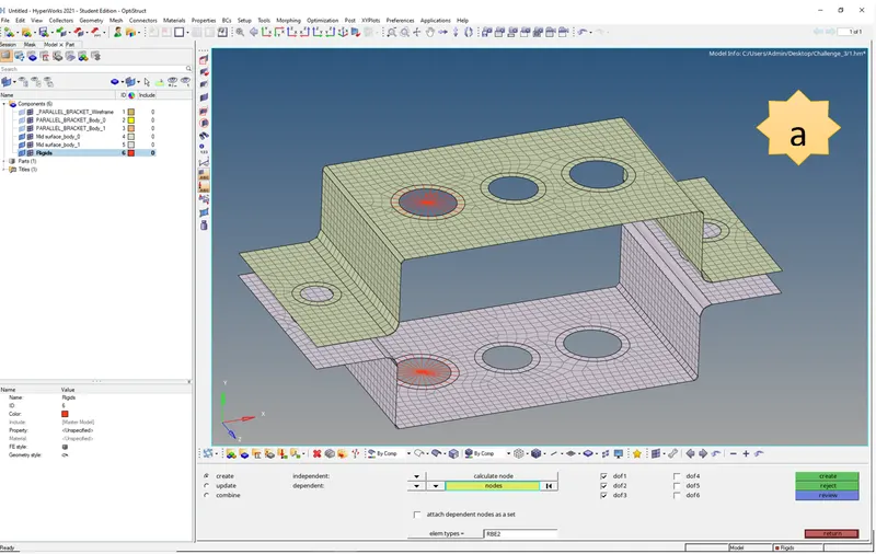
- Now create different components for mass, spring, Rod, Beam, Bar elements
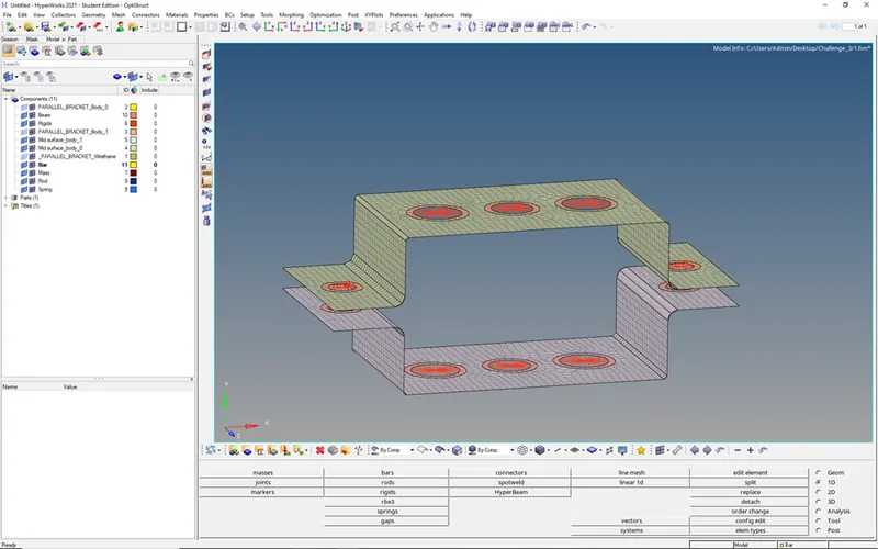
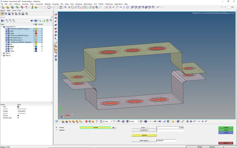
- Add mass of magnitude 10 at d & e places
- Goto 1D -> masses -> select node and enter the magnitude of 10 units
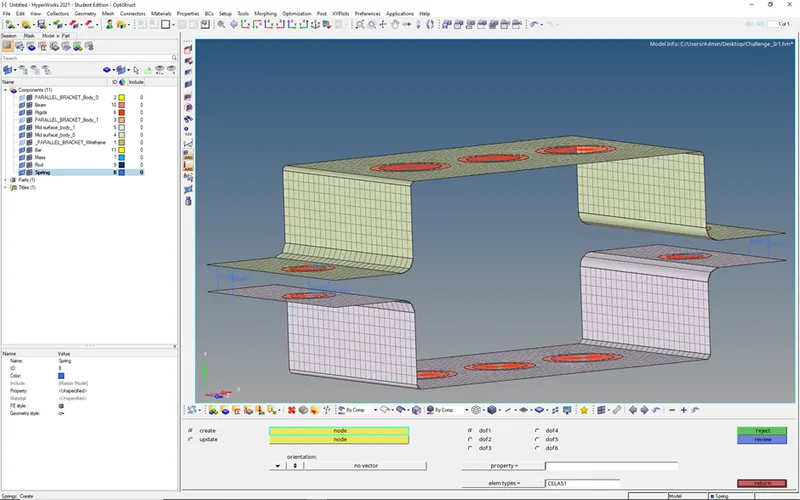
- Add spring at f location
- Goto 1D -> springs
- Now create the cross-sections for Rod, Beam, Bar elements
- Goto 1D -> HyperBeam -> choose hyperbeam in standard section library

Input dimensions given in the problem
- To define X cross-section choose optistruct in the standard section library

- Input the dimensions given in the problem
- After defining the cross-sections, we need to define material and property
- Material we can add default one (Steel)
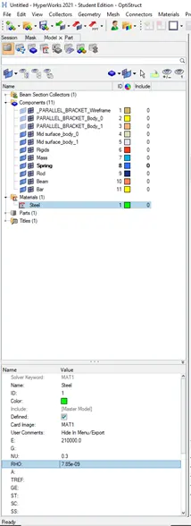
Property:
- Property can be defined individually for each component (2 mid surface bodies and Rod, Beam, Bar elements)
For components:
- Material as steel, Card Image as PSHELL, and thickness as 5mm
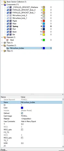
- Now define the properties for Rod, Beam, Bar elements
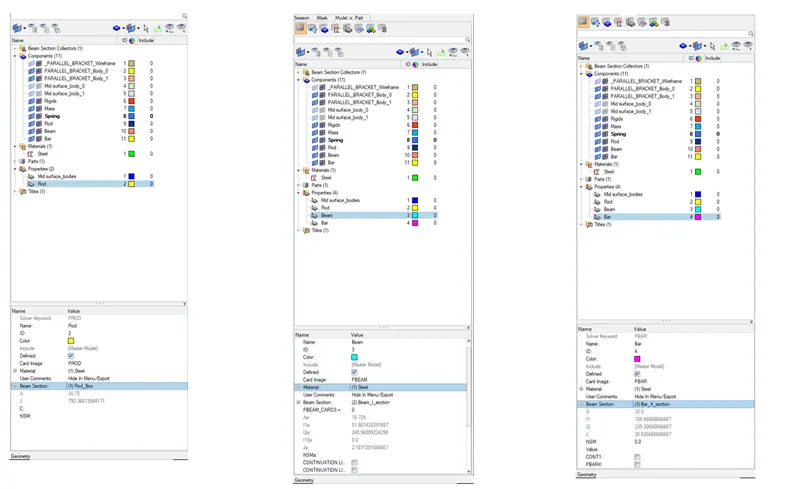
- Add mid surface property to the mid surface components
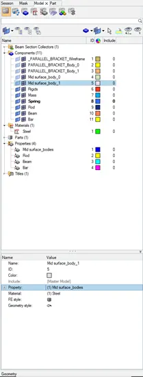
- Add Rod, Beam, Bar elements properties to the respective components
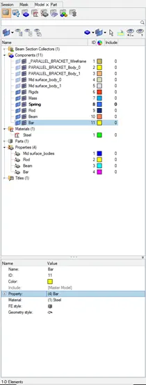
- Now define the Rod, Beam, Bar elements positions in the bracket as per the given question
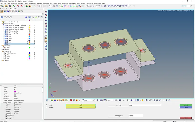
- Goto 1D -> Rod -> select the nodes to add rod element (Element type CROD and select the property)
- Choose current component as Rod
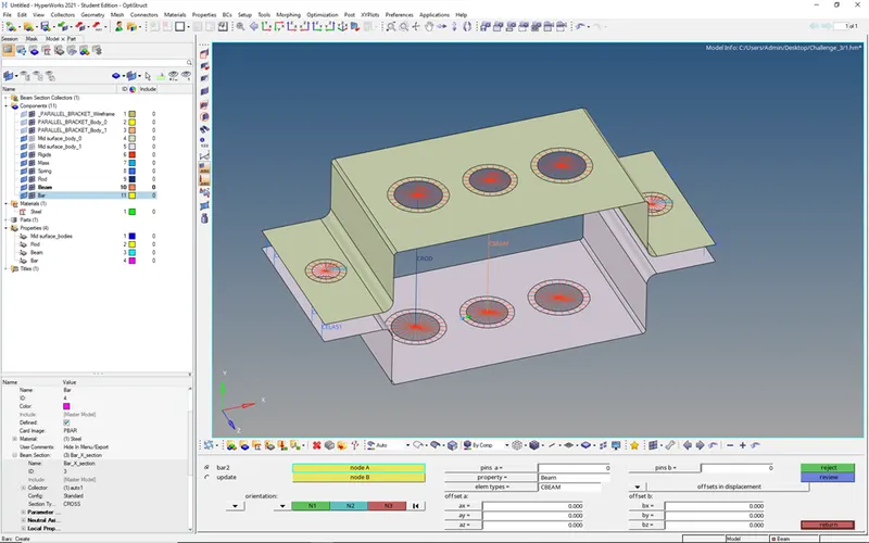
- Goto 1D -> bars -> pick nodes, element type and property to add beam element
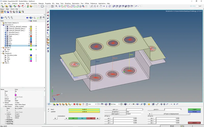
- Goto 1D -> bars -> pick nodes, element type and property to add bar element
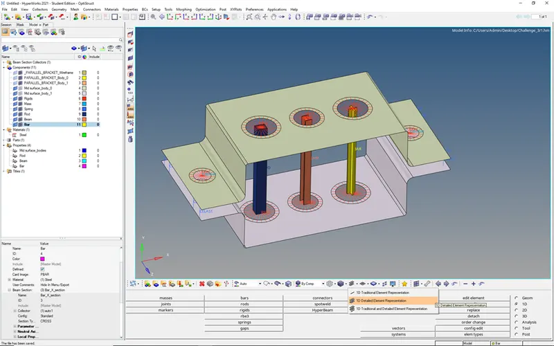
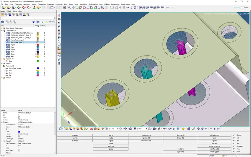
- Now to visualize 1D Elements in 3D Mode
- Goto 1D Detailed Representation
-
Final Visualization: