Week 4-1D Element Creation Challenge
Creating 1D Elements, assigning and updating properties, materials, Creating Sections Using HYPERMESH
Objective:
- To Mesh the Given component with the Size of 5 Units. Create 1D elements on the following component with given cross-section and DOF
- Rod element (for a): Translational DOF should be Constrained with RBE2 link (Cross-Section: BOX- Dimension a= 12 mm, dimension b=10 mm, Thickness t= 0.75 mm).
- Beam element (for b): All DOF should be constrained with RBE3 link (Cross-Section: I Section- Dimension a= 8 mm, Dimension b= 10 mm, Dimension c= 8.5 mm, Thickness t1= 0.75 mm, Thickness t2= .6 mm, Thickness t3= .6 mm.
- Bar element (for c): Constrain only xand y DOFs With RBE3 link (Cross-section: X section- Dimension DIM1= 5 mm, Thickness DIM2= 1.2 mm, Dimension DIM3= 10 mm, Thickness DIM4= 1.2mm.
- For d & e, Apply the mass of magnitude 10 with the RBE2 link.
- For f, Join the two components with Spring elements.
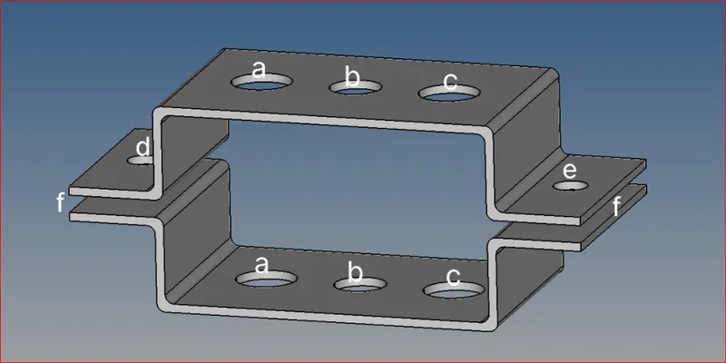
Imported CAD Model:
- Go to File >> Import-Geometry >> (Select file) >> Import
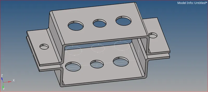
Imported CAD geometry
Geometry clean-up and Mid surface generation
- Then clean up the geometry manually and check whether the components are connected properly and the surface is filled or not.
- After checking geometry, proceed with the model to the mid surface by selecting Geometry >> mid surface >> and select the elements that you want to take mid surface.
- In this model, we have two brackets and both are the same as each other while we taking the mid surface in hypermesh there are 4 options available to us. They are shown below in the picture.

Mid-surface extraction options
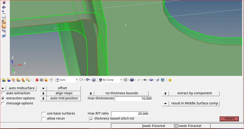
Mid-surface using offset
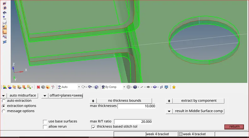
Mid surface using offset + planes + sweep
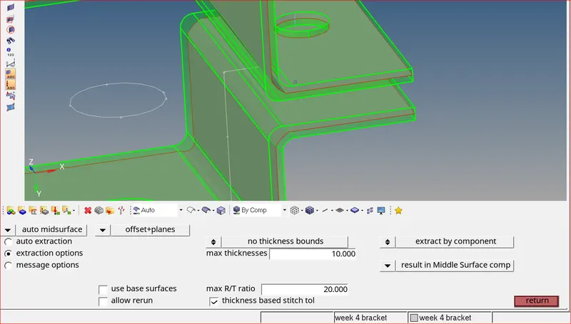
Mid-surface using offset + planes
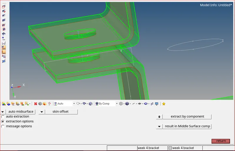
Mid-surface using skin offset
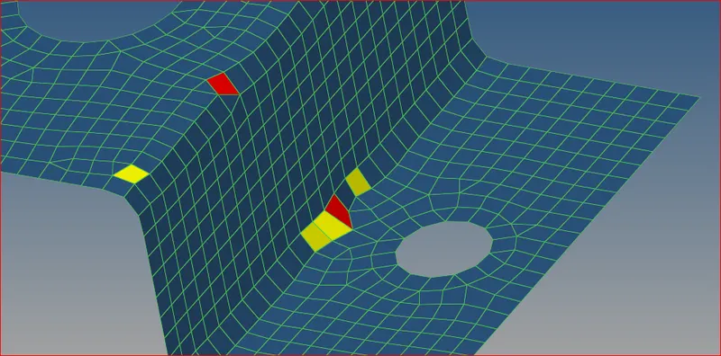
Irregular edges cause quality issues
- I have tried all these 4 options and I chose skin offset to extract mid-surface. The remaining options did not capture the edges perfectly. Edge capturing is important because it can later lead to irregular mesh-flow and quality issues during meshing.
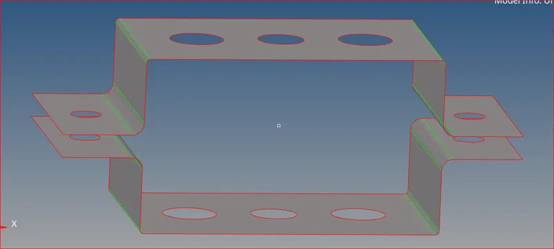
Mid-surface generated using skin offset
- Now remove all the solids using the delete option. Also, remove all the remaining components other than mid surface 1 and mid surface 2.
Organizing components in hypermesh
- After the mid surface is generated for the whole component. We can divide mid surfaces into n number of components.
- 1st we need to create the components. I have created mid-surface 1 and mid-surface 2.
- I will make mid surface 1 as the current component (right-click on the component and make it as current). Now go to tools >> organize >> select surfaces >> click on the move.
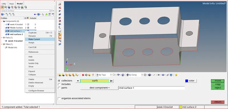
Organizing mid surface to component
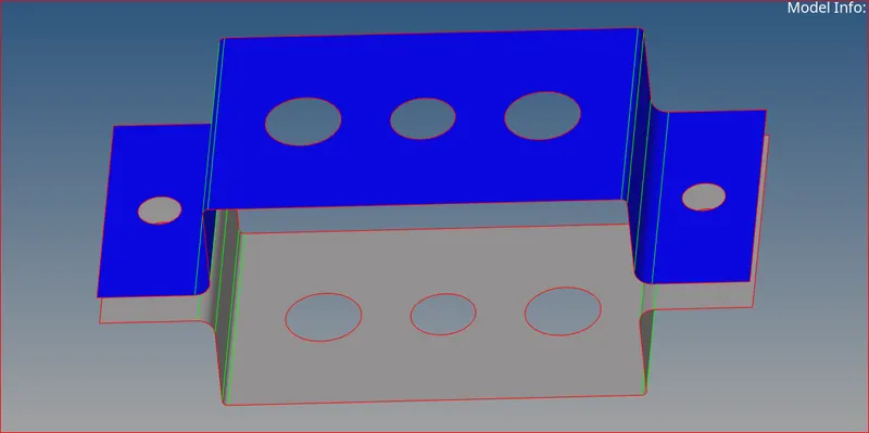
Organized surface to mid surface 1
- Similarly, organize the 2nd mid to mid surface 2 (component).
- Create a washer split at the holes as these splits give us better mesh flow and rigidness at the holes.
- Geometry >> quick edit >> washer split and enter the offset values as 5mm >> click that hole to create the washer around the hole.
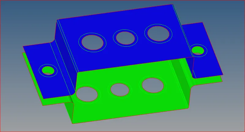
Washer splits
Assigning Properties and Materials in hypermesh
- We can create properties and materials simply by right click >> create >> property or material
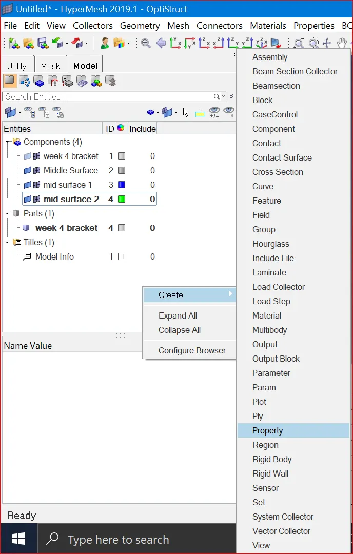
Creating property
- I have selected card image as MAT1 for material, which is nothing but steel.
- For properties, I have selected card image as PSHELL, as these are surfaces, and also assigned steel as their material.
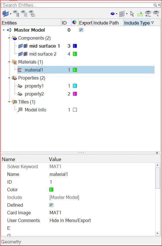
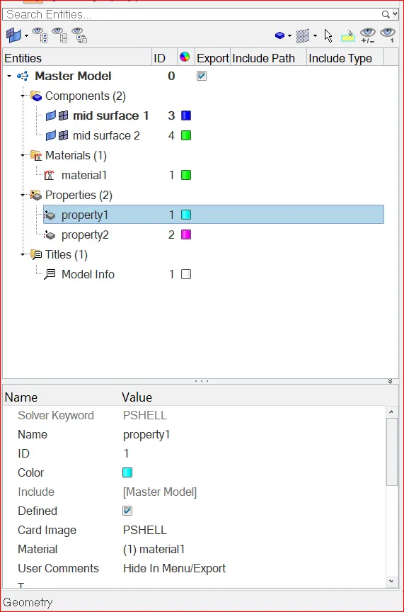
Assigining Material Assigning Property
- Now go to the component section and assign property, then it will automatically take the material. Therefore, materials and properties are assigned to mid-surface 1 and mid-surface 2.
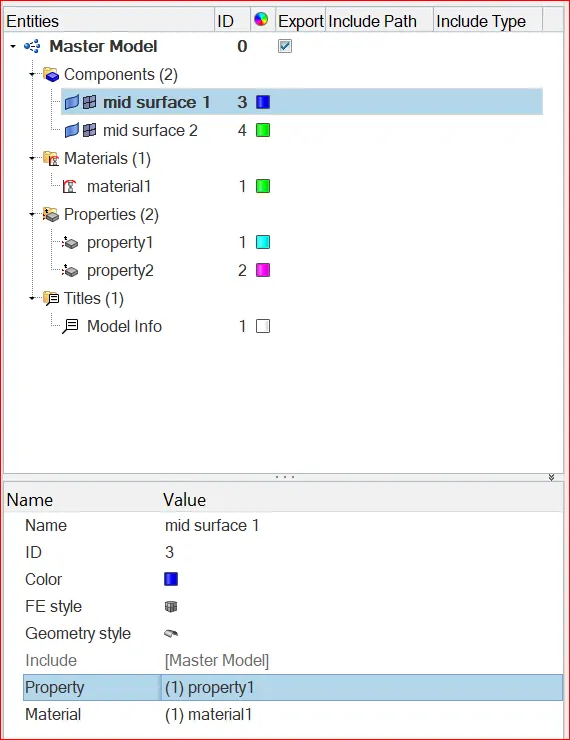
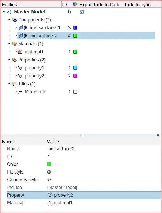
Assigning Property and material to mid-surface 1&2
Mesh generation for components
- Now create the mesh for the two brackets by selecting 2D >> auto-mesh >> enter element size as 5mm>> select the surface to create mesh on that surface.
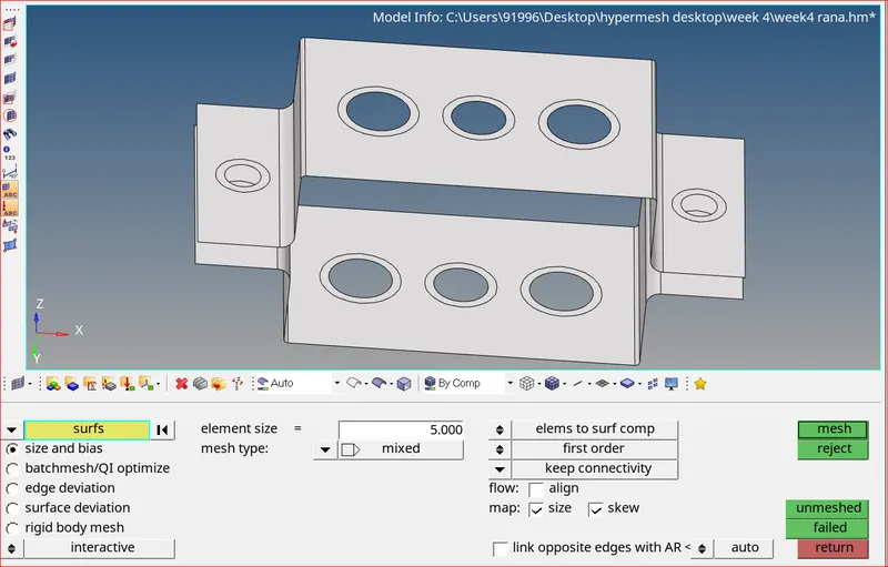
Surfaces selected for mesh generation
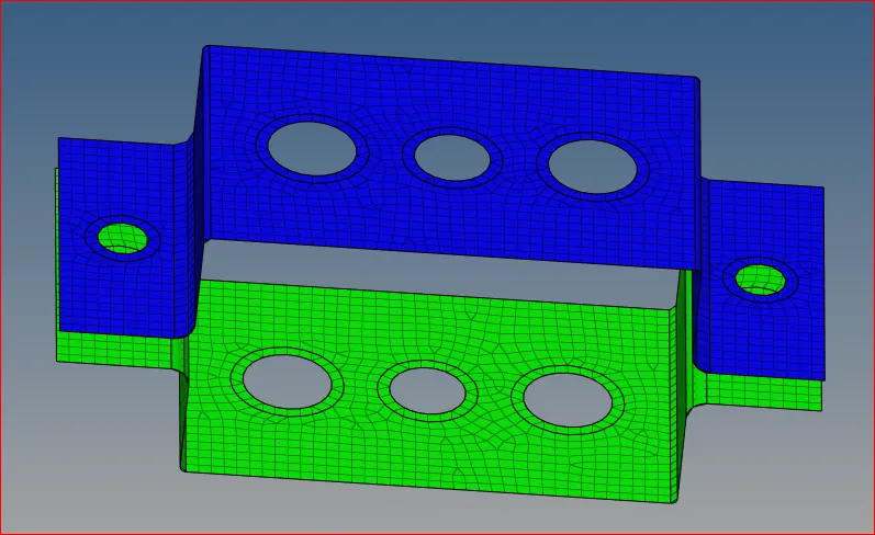
Mesh generated
- Therefore, mesh generation for bracket is successful. Now we must check quality index of the mesh which we have generated. Go to 2D >> quality index. Since there are no quality indices we can move forward for connections.
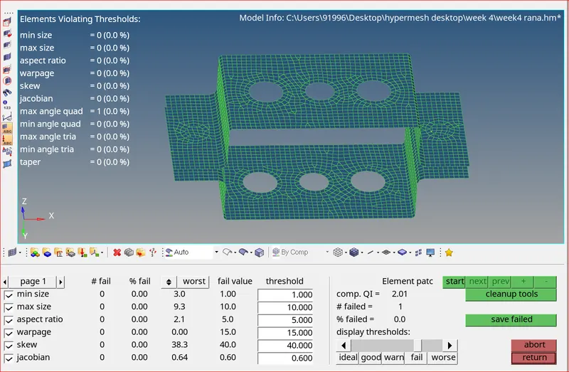
Checking quality index of mesh
Connections
- Rigid elements are basically RBE2 elements. These elements have infinite stiffness. These elements never bend, rotate, or move. In RBE2, the load distribution is uniform irrespective of the position from the load.
- I have created RBE2 elements at a, d & e respectively
- Translational DOF is Constrained with RBE2 at 2. Therefore, untick dof1, dof2, dof3 while giving connection.
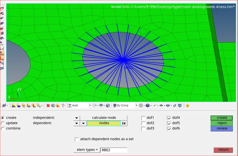
RBE2 element at a
- Similarly, create RBE2 elements at d & e.
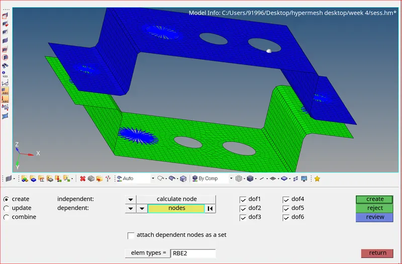
RBE2 elements at d & e
- In RBE3 elements, the load distribution depends on the distance from the load. Load distribution is more on the nodes closer to the load.
- Now create RBE3 elements at b (all dof’s constrained)
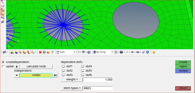
RBE3 at b
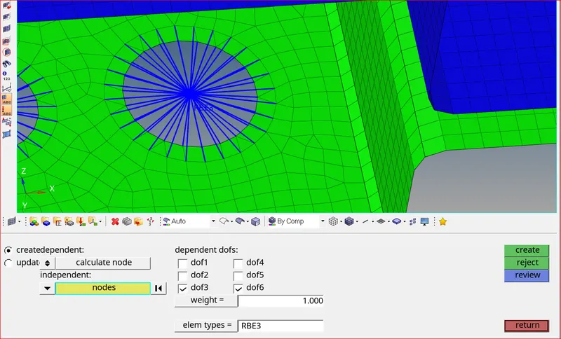
RBE3 at c
Creating 1D elements in hypermesh
- 1st create rod element at “a”. go to 1D >> rods >> select nodes >> select element type as CROD
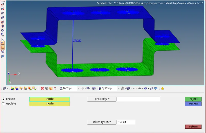
Creating CROD at a
- Similarly create bars at “b” and “c”. go to 1D >> bars >> select nodes >> orientation >> element type (CBEAM or CBAR)
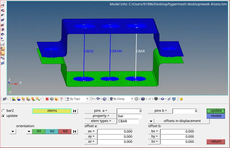
CBEAM AND CBAR created at b & c
Creating sections using hyper beam
- Now create Box Section at “a” with given dimensions (a= 12 mm, b=10 mm, Thickness t= 0.75 mm)
- Go to 1D >> Hyper beam >> Standard section >> select section library and type >> Create
- Then it will take you to hyper beam, where you can edit all the dimensions of the section which we have given.

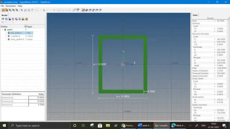
Creating BOX-section in Hyper Beam
- Similarly create I section and X section according to the required dimensions. (create >> standard selection >> optistruct >> CROSS for X section)
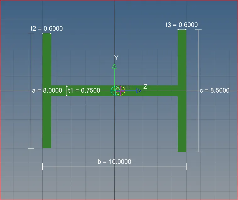
Creating I-section in Hyper Beam
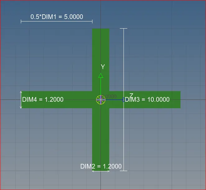
Creating CROSS-section in Hyper Beam
Assigning hyper beam sections to 1D elements(connections)
- Create 3 separate properties for CROD, CBEAM and CBAR.
- Now assign the box, I, X sections to the required 1D elements. This process is shown in below figures
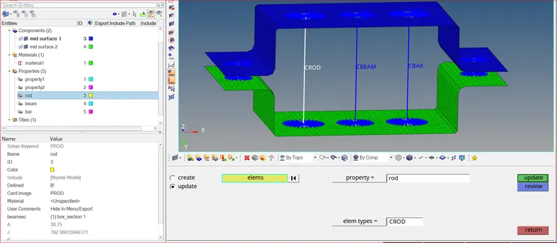
Updating BOX to CROD
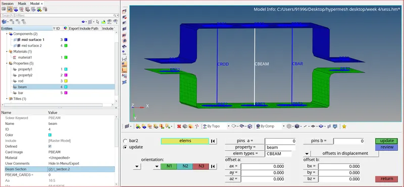
Updating I-section to CBEAM
Updating CROSS-section to CROD
- After updating the sections, switch to 1D detailed representation view so that the created sections will be visible to us.
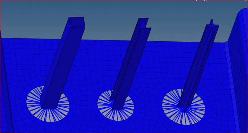
Generated BOX,I,CROSS sections
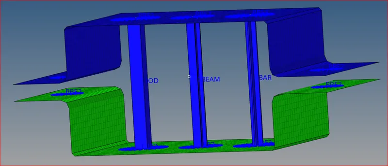
Required sections are updated successfully
Assigning Mass to 1D elements
- Now apply the mass of magnitude 10 at of d & e. Go to 1D >> masses >> select nodes >>
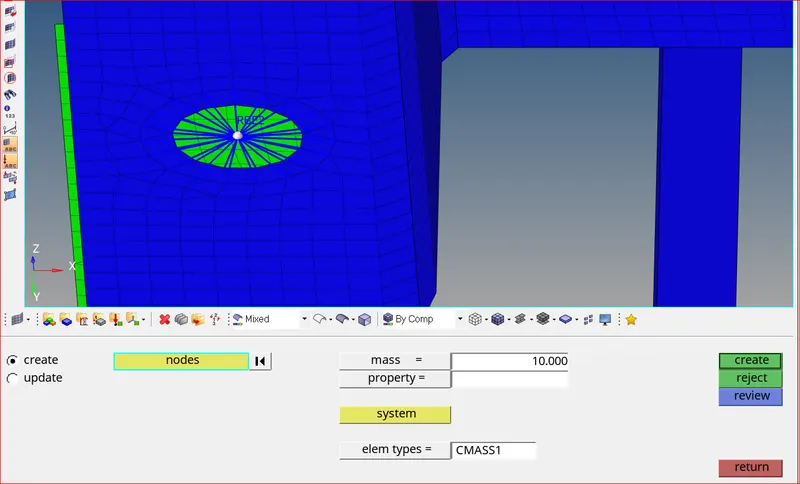
Assigining Mass
Joining components using spring elements
- Select the two nodes in between the two brackets and assign the property as spring. Select the element types as CELAS1 and click the create option.
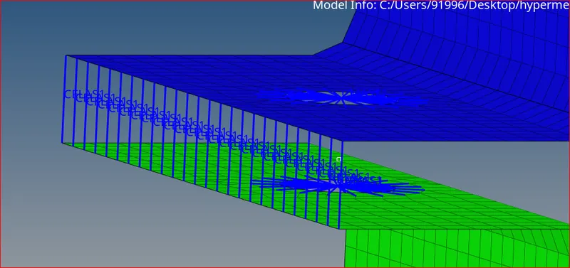
Spring connection generated
RESULT:
- Hence all the required objectives are fulfilled:
a - Rod element Created with only translational DOF and RBE2 link.
b - Beam Element Created with all DOF and RBE3 link.
c - Bar Element Created with only x & Y DOF and RBE3 link.
d & e - Mass added on the Master node of RBE2 link.
f - Two Components were joined with Spring Elements.
Learning Outcomes:
- Successfully imported the model and performed geometry clean up
- Meshing and improvement of mesh
- Assigning properties, materials, components
- Creating 1D connections, masses, springs
- Using hyper beam to create different types of sections
Final Model Image:
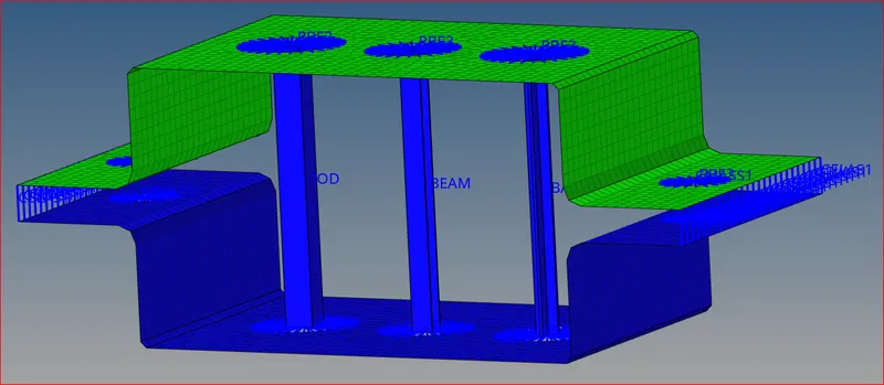
Drive link: https://drive.google.com/file/d/1yPUTb4kcQ10ZcegQoCIpQkY5nwk0yYJ4/view?usp=sharing