Week 4-1D Element Creation Challenge
OBECTIVE :
Mesh the Given component with the Size of 5 Units. Create 1D elements on the following component with given cross-section and DOF
a. Rod element:- Translational DOF should be Constrained with RBE2 link
Cross-Section: BOX- Dimension a= 12 mm
dimension b=10 mm
Thickness t= 0.75 mm
b. Beam element:- All DOF should be constrained with RBE3 link
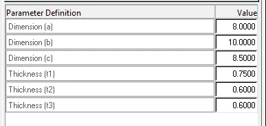
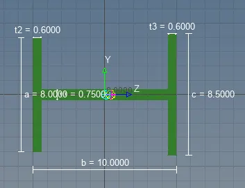
Cross-Section: I Section- Dimension a= 8 mm
Dimension b= 10 mm
Dimension c= 8.5 mm
Thickness t1= 0.75 mm
Thickness t2= .6 mm
Thickness t3= .6 mm
c. Bar element:- Constrain only x and y DOFs With RBE3 link
Cross-section: X section- Dimension DIM1= 5 mm
Thickness DIM2= 1.2 mm
Dimension DIM3= 10 mm
Thickness DIM4= 1.2mm
d. & e. Apply the mass of magnitude 10 with the RBE2 link
f. Join the two components with Spring elements
PROCEDURE:
- Improt the CAD model
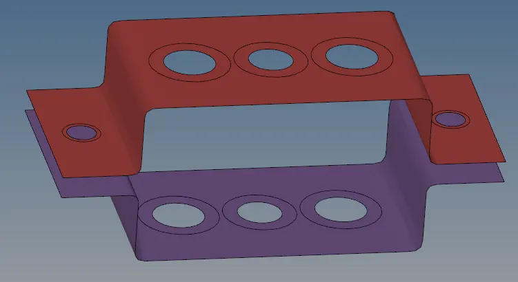
- Extract the mid surface in CAD model by removing solid with adding wacthers as shown below
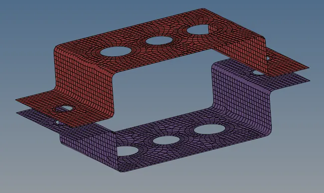
- Mesh the mid surface with 5 units as shown below.
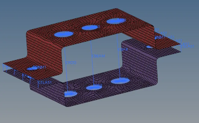
- Create RBE2 with constraining translationa; DOF for rods. Create RBE3 for both bar and beam element with constraining X & Y DOF for bars and constrain all DOF for beam elements as shown below.
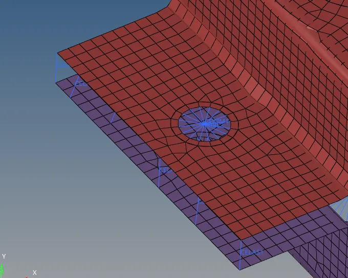
- Apply the mass of magnitude 10 with the RBE2 link and Join the two components with Spring elements.
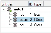
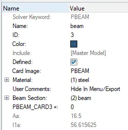
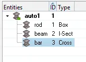
- Upload the material,properties and cross section dimension for rod,beam and bar as per given in question.
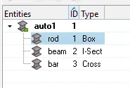
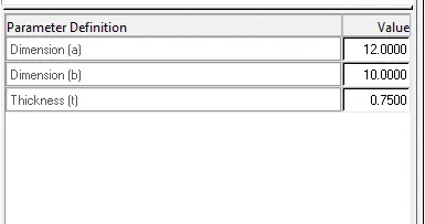
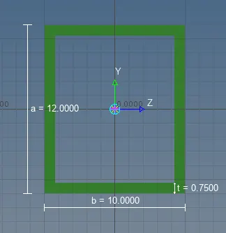
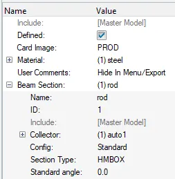
CROSS SECTION DIMENSION & PROPERTY VALUE FOR ROD
CROSS SECTIION DIMENSION & PROPERTY VALUE FOR BEAM
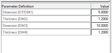
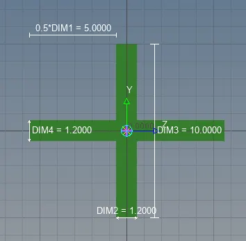
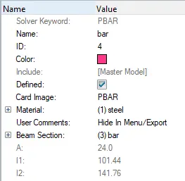
CROSS SECTIION DIMENSION & PROPERTY VALUE FOR BAR
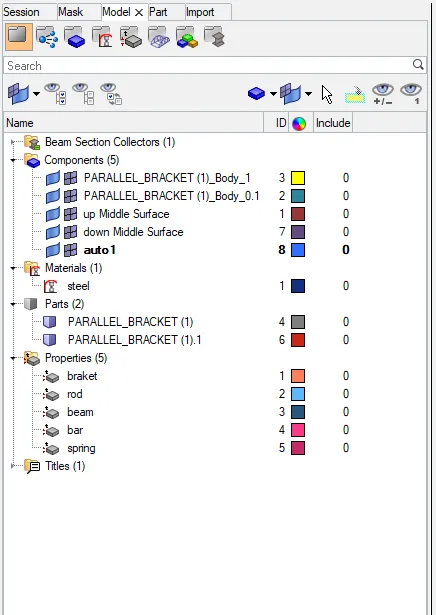
NUMBER OF COMPONENTS AND THEIR MATERIALS
CONCLUSION:
- We understand how to allot 1D to beam,bar and rod and we also understand hyperbeam,the result shown below figurs.
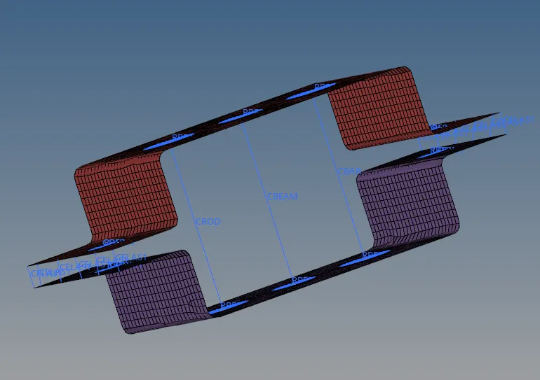
Fig: 2D view of designed component
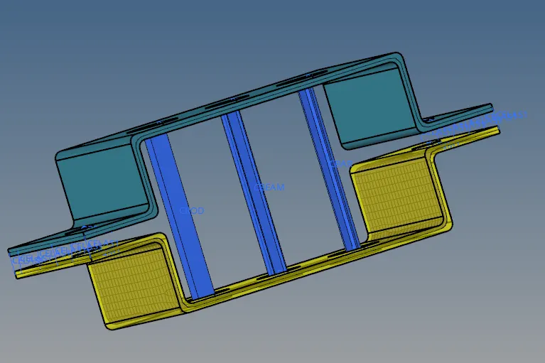
Fig: isomatric view of designed component
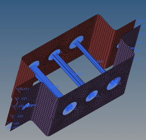
Fig: how rod,beam and bar connected to brackets
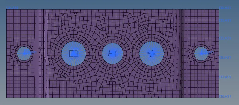
Fig: top view of how rod,beam and bar connected to brackets