Week 4-1D Element Creation Challenge
AIM:
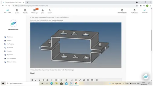
To mesh the component with 5 units and to create 1D elements with below cross section and applying DOF accordingly as per requirement
Observations:
learnt various 1-D elements and their applications and their usage in hyper-mesh accordingly explained their practical applications as examples
Rigid element (RBE2):
Element where it has infinite stiffness that element is called as rigid element
For instance consider engine case for dynamically moving, the engine can be modelled as a mass element connected by an RBE2 rigid element to the engine's multiple mounting locations. This makes the reasonable assumption that the engine is "very stiff" compared to the body structure. The mass is located at the centre of gravity of the engine, and the rigid element links the engine mass to the rubber mounts (e.g. springs or bushes) whose stiffness’s are typically much more relevant
RBE3 link:
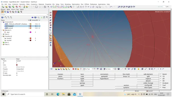
RBE3 is rigid link that will not induce sufficient stiffness, which means RBE3 elementsserve to distribute loads without inducing unwanted stiffness. It is not an element to be used to model a connection, but rather an element to induce a motion in a node as a function of the weighted average of other nodes
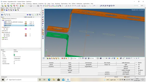
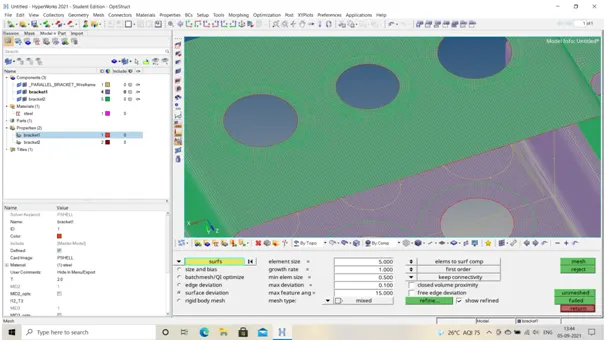
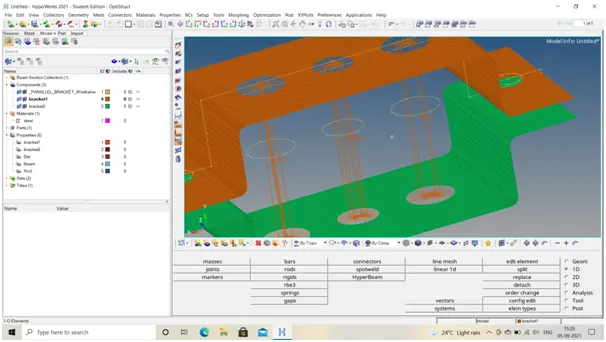
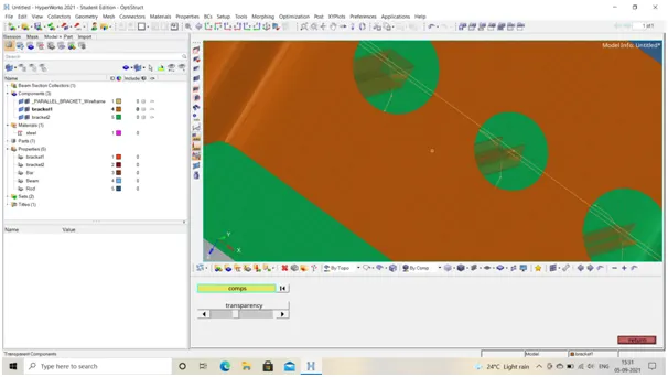
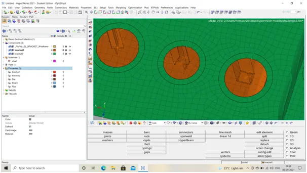
In order to understood it better I created mesh at holes with & without spilt washer option observed how it will affect the meshing
Bar element:
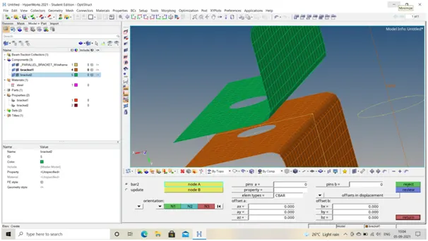
1-D element axial element takes axial load as well as bending, this dimensional structure resists mostly axial loads
CBAR in hyper mesh requires shear centre as well as neutral axis to coincide
Any offsets between the neutral axis and the shear centre is not accounted for. As a consequence, CBAR elements are not useful for modelling beams that warp as it may be the case with open channel sections. Thisis because,the cross-sections of CBAR elements remain plane.
Beam element:
1-D element simple and most commonly used structural component for loads suchas bending, shear,symmetrical beam element is preferable
Traditionally straight bar, often it has various cross section like square, rectangular, T-shaped, C-shaped, H, I sections, circular sections
It is used wherever properties like cross-section is symmetrical for CBEAM not necessarily require shear centre
Rod element:
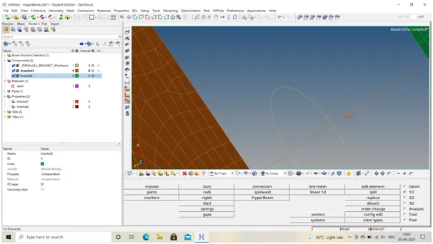
It allows only compression and tension only it has only translation degree of freedoms but it experiences torsional stiffness if load acts in that direction
Spring element:
The spring element is a one-dimensional finite element where the local and global coordinates coincide. It should be noted that the spring element is the simplest finite element available
Properties of spring element:
- That absorbs shock
- Have high yield strength
- Ability to resist deformation
Degree of Freedoms:
As it goes by definition of mechanicsNo of independent parameters that define its configuration or state
Its 3 translational and 3 rotational when an object is placed in space here we DOF to arrest motion of 1 D elements to attain desired output or else defining proper boundary conditions
Technique followed:
Firstly I created mid surface which is shell representation of solid model it is used to reduce the computational expense and time for analysing the component
I understand that we are applying the loads directly on neutral fibre it has limitation while doing it though we are minimizing computational expense but actually the top and bottom fibre aren’t undergoing significant stress while bending
With the help of auto mid-surface created the 2D representation then deleted the original surfaces
Thus created mid surfaces for bracket1 and bracket2
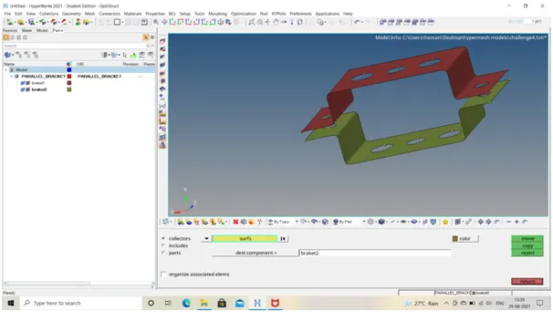
Assigned material to the bracket as steel
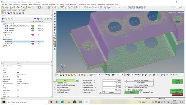
Then meshed above component in various conditions with spilt washer and without spilt washer with mesh size as 5 units
Without spilt-washer
With spilt-washer
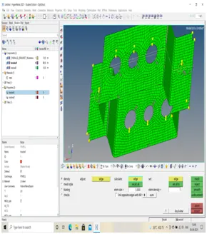
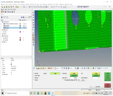
Created properties for Bar, Beam, rod assigned those values of cross section to the properties and also material as steel
Created RBE2 and RBE3 links as per requirement @ a, b, c as per specified model
- Rod element:- Translational DOF should be Constrained with RBE2 link
Cross-Section: BOX- Dimension a= 12 mm
Dimension b=10 mm
Thickness t= 0.75 mm
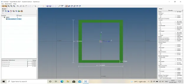
Choose card image as PROD
- Beam element:- All DOF should be constrained with RBE3 link
Cross-Section: I Section- Dimension a= 8 mm
Dimension b= 10 mm
Dimension c= 8.5 mm
Thickness t1= 0.75 mm
Thickness t2= .6 mm
Thickness t3= .6 mm
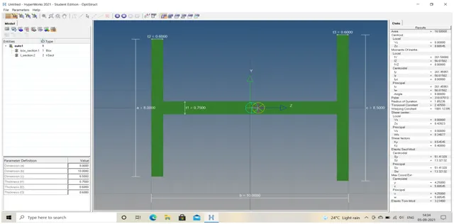
Choose Card image as PBEAM
- Bar element:- Constrain only xand y DOFs With RBE3 link
Cross-section: X section- Dimension DIM1= 5 mm
Thickness DIM2= 1.2 mm
Dimension DIM3= 10 mm
Thickness DIM4= 1.2mm
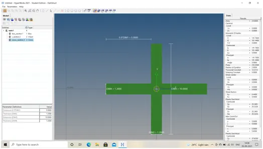
Choose card image as PBAR
Later assigning cross section
For CBAR initially given CMASS as ten units later edited zero units to identify the difference
For above all three cross section statsifited all boundary conditions as per requirement
Finally given mass of 10 units to d &e holes by creating RBE2 link
For spring elements created spring link at all four corners of the bracket connecting entire bracket as one
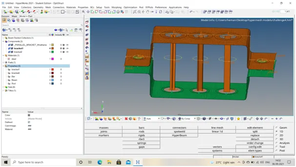
Conclusion:
Understood basics of 1-D elements and their properties, learnt difference between RBE2 and RBE3 links Explored various other options while practicing the model finally developed the component with 5 units of element size and created links, elements and applied boundary conditions as per requirement