Week 4-1D Element Creation Challenge
OBJECTIVE:
Extract mid surface of given component & perform 2D meshing. The element size must be 5 mm. There is some spot identified as alphabet from a to f. We have to apply (1D Element along with corresponding links) the rod, bar, beam, & spring elements as specified in the problem statement. We have to also take care of the degree of restrains as specified. The proper cross-section must be applied to 1D elements.
SOLUTIONS:
LET'S visualize a 3D model
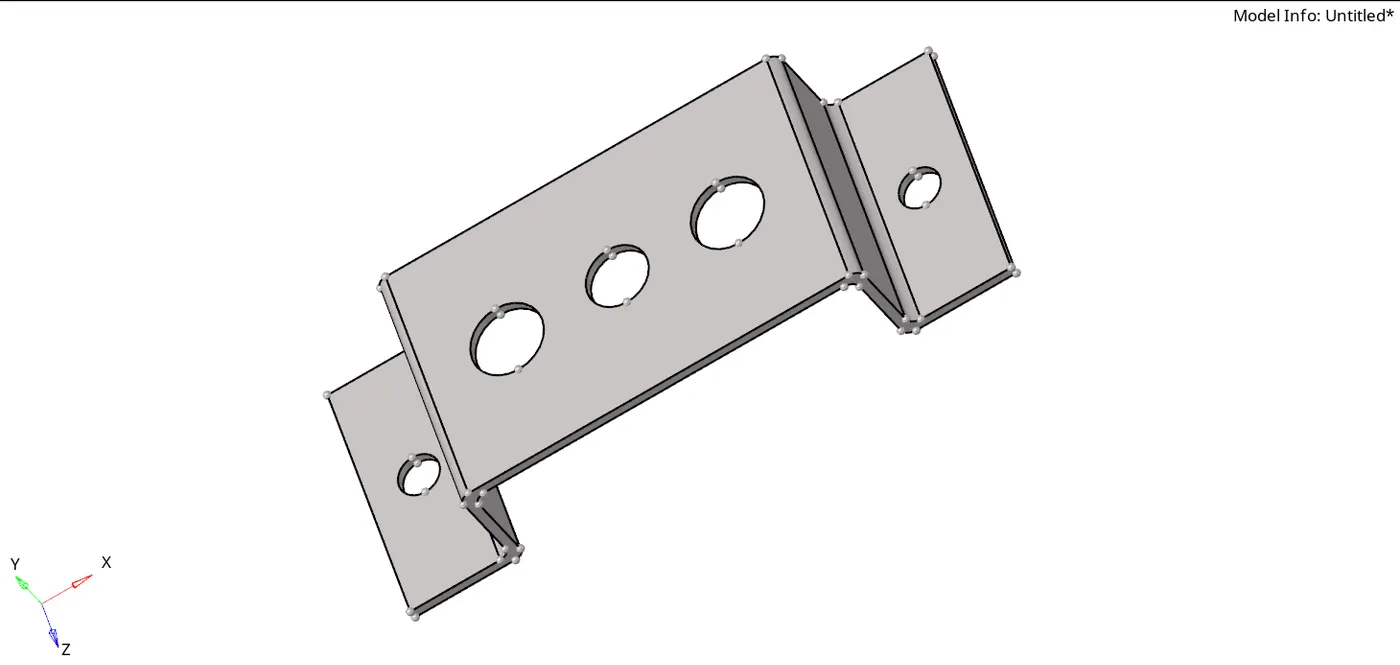
There is 2 bracket each having 3 holes as we can see clearly in the above image. We will extract mid surface from the above geometry as shown below
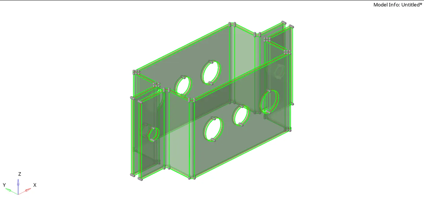
We can see a red color edge after creating the mid surface. These are known as free edges & confirms that mid surface has been created. Now we will visualize mid surface only after hiding all other entity
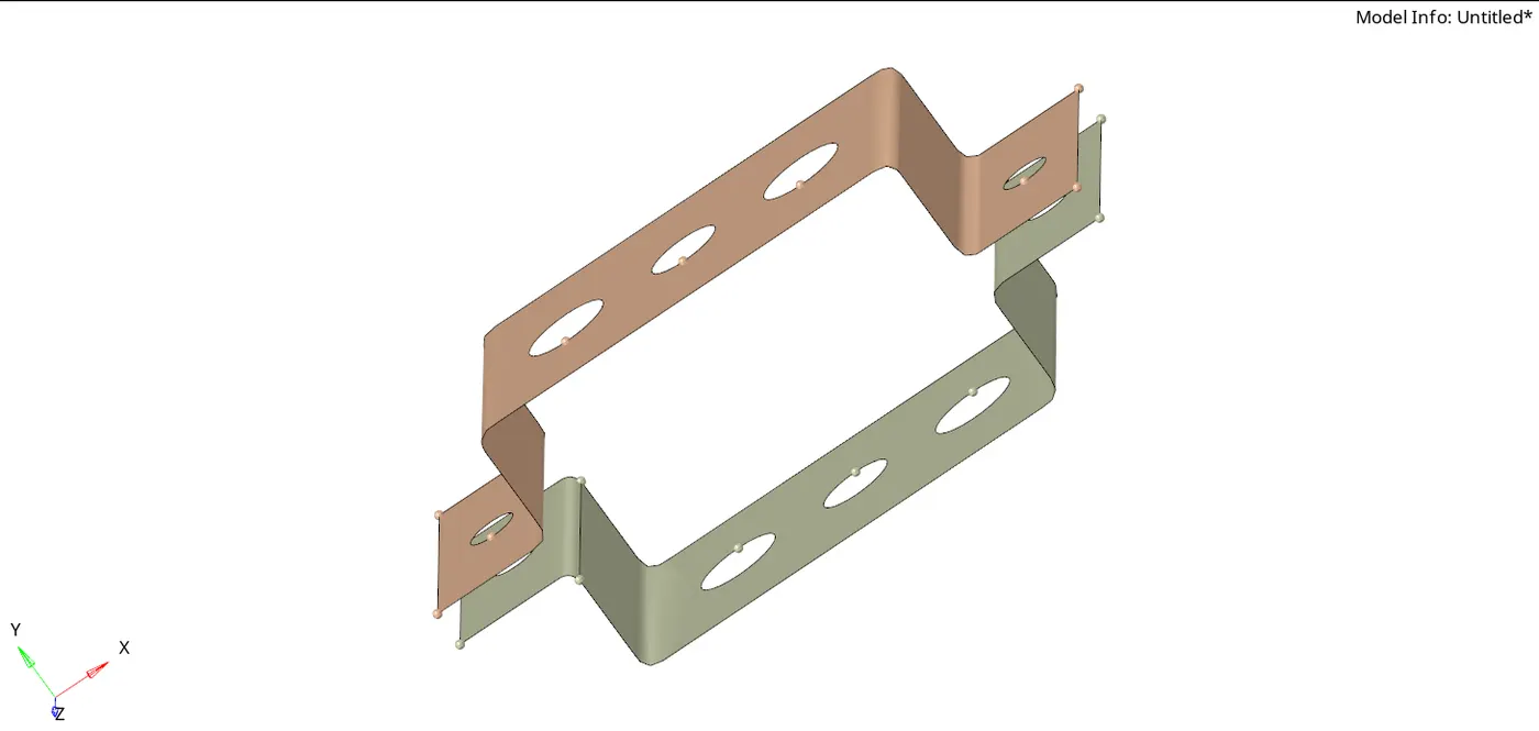
We have given a different color to both surfaces to identify them individually. We can confirm that our mid surface has been created successfully. Now we will assign thickness & material under the property section as shown below
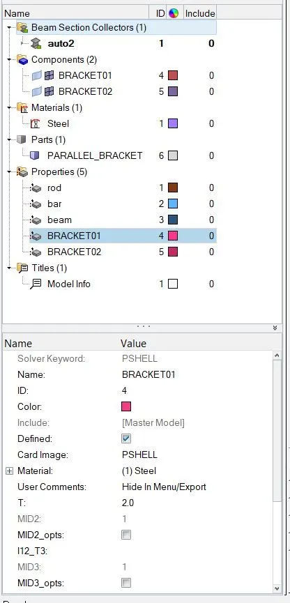
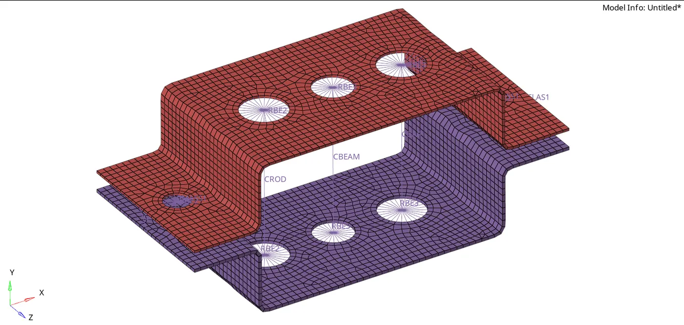
The above image shows the entire setup created for this task. We have chosen steel as a material for both brackets. The thickness of both brackets is different. We can confirm the thickness in the figure below. The red color component has a thickness of 2mm & the blue color comp[onent has a thickness of 2.5 mm.
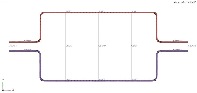
Also, as per the given statement, we have applied BEAM, BAR, ROD, & SPRING elements as per specified location and proper link. We have also applied proper crosssection to each 1D element as per the given dimension. These 2 images (above & below) can clearly specify each 1D element.
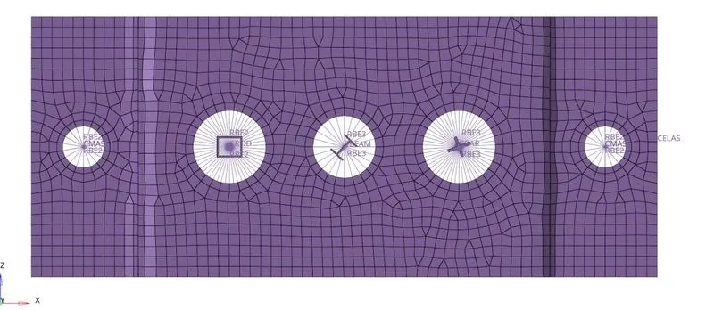
We will discuss crosssection of each 1D element
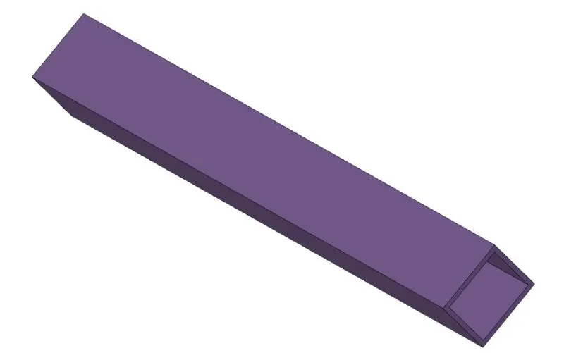
1. Rod element:- Translational DOF should be Constrained with RBE2 link
Cross-Section: BOX- Dimension a= 12 mm
dimension b=10 mm
Thickness t= 0.75 mm
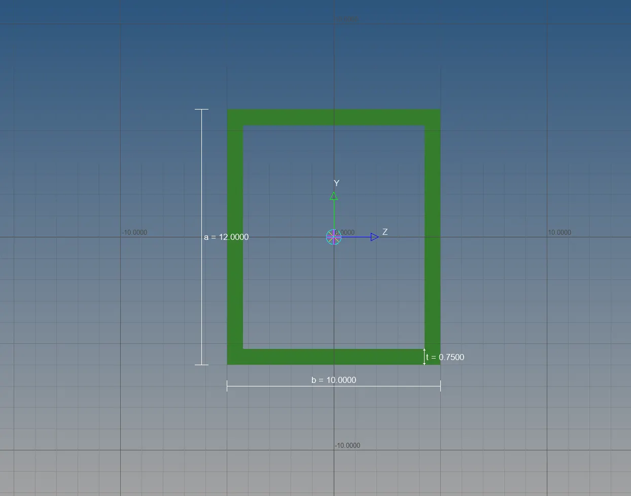
3d view
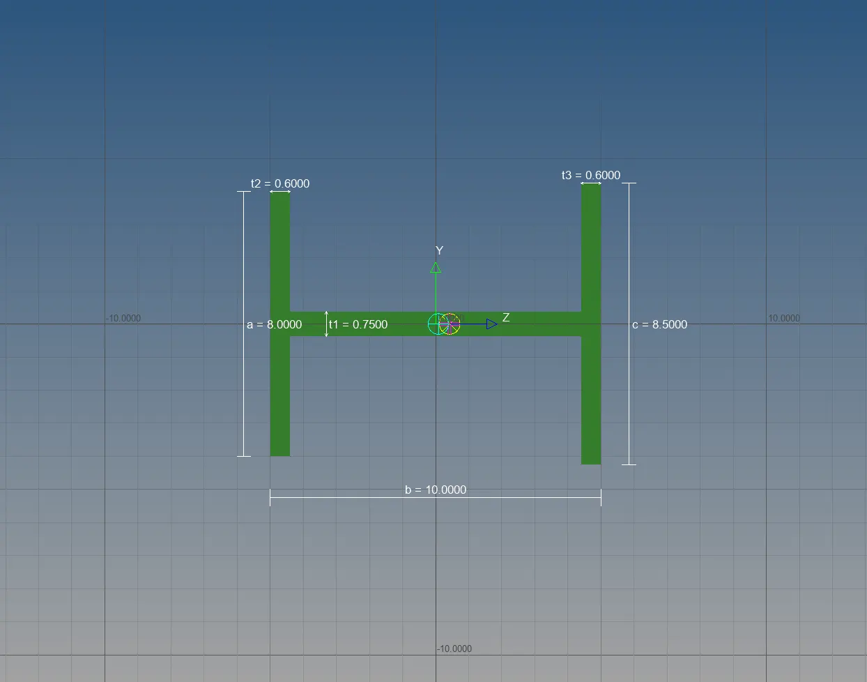
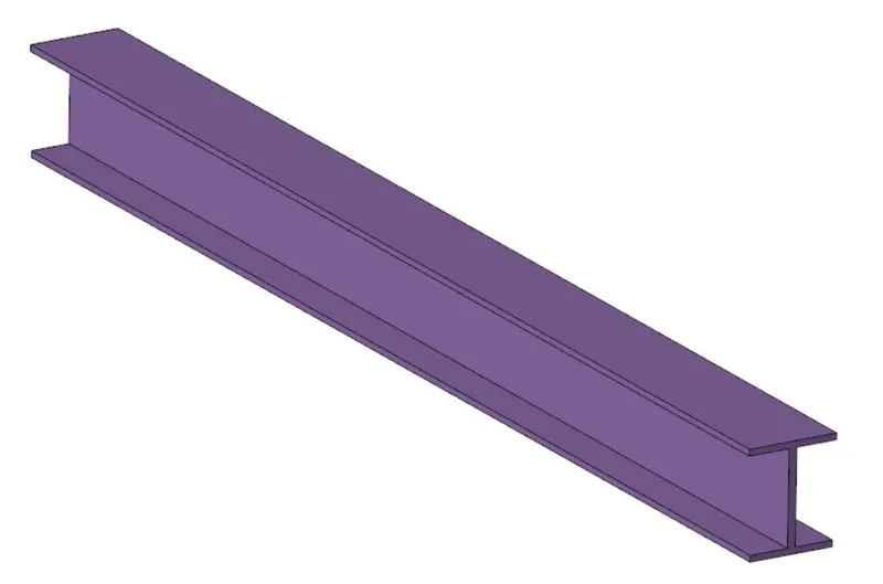
2. Beam element:- All DOF should be constrained with RBE3 link
Cross-Section: I Section- Dimension a= 8 mm
Dimension b= 10 mm
Dimension c= 8.5 mm
Thickness t1= 0.75 mm
Thickness t2= .6 mm
Thickness t3= .6 mm
3d view
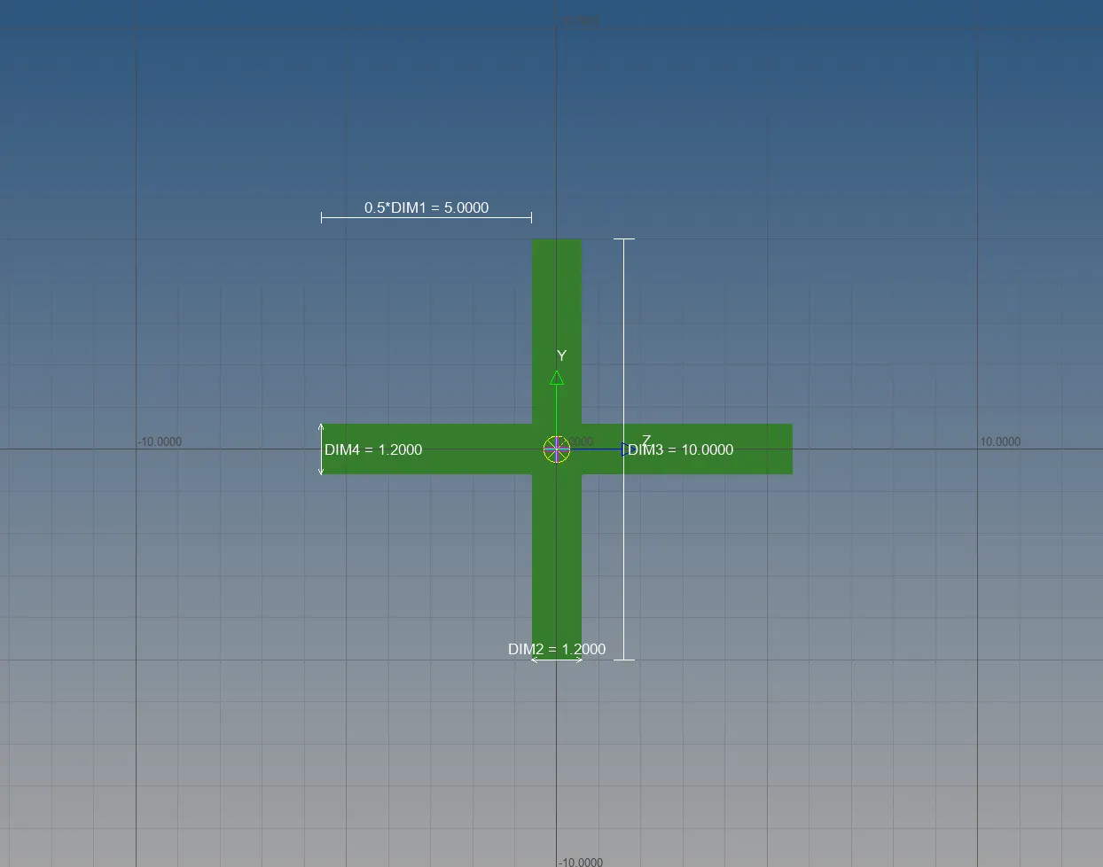
3.
Bar element:- Constrain only x and y DOFs With RBE3 link
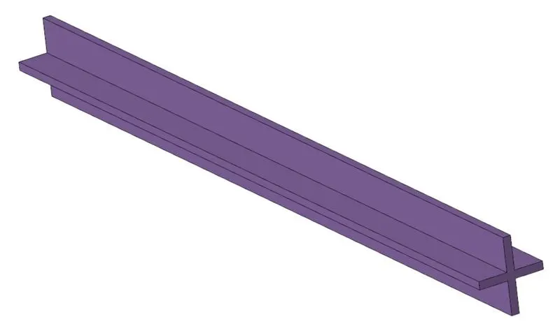
Cross-section: X section- Dimension DIM1= 5 mm
Thickness DIM2= 1.2 mm
Dimension DIM3= 10 mm
Thickness DIM4= 1.2mm
3d view
Before starting shell meshing we need to perform autocleanup in order to identify & rectify some features like hole, fillet, etc. We can see geometry before cleaning as shown below
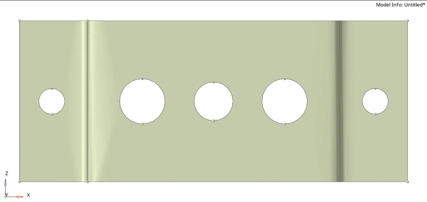
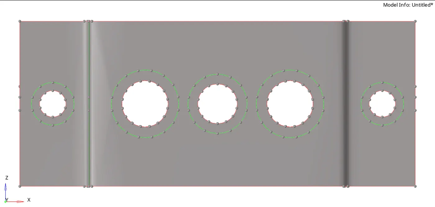
Once we perform auto cleanup we will find some washer split around hole as shown below. These help in correcting near hole mesh.
Below image shows mesh in bracket1
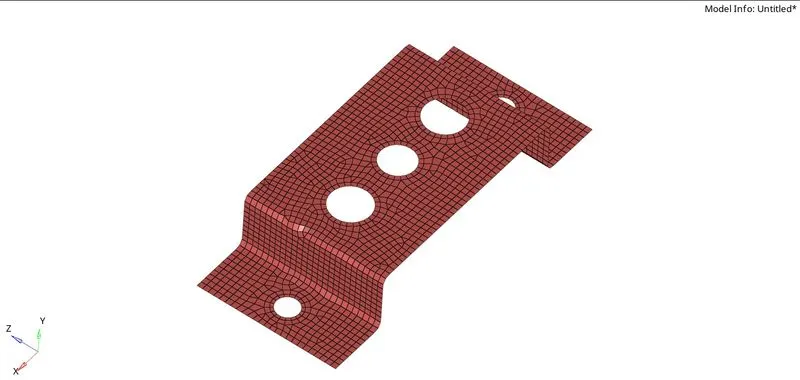
Below image shows mesh in bracket2. We can see minimum distortion of element within washer split.
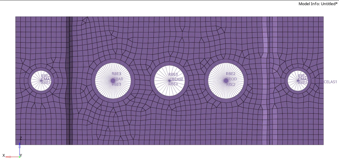
Figure below shows entire component with thickness provided to corresponding midsurface shown along with meshing & all 1D elements.