Week 4-1D Element Creation Challenge
Aim :-
Mesh the given Bracket and create 1D element with respective DOF to the cross-section.
Data Provided :-
a. Rod element:- Translational DOF should be Constrained with RBE2 link
Cross-Section: BOX- Dimension a= 12 mm
dimension b=10 mm
Thickness t= 0.75 mm
b. Beam element:- All DOF should be constrained with RBE3 link
Cross-Section: I Section- Dimension a= 8 mm
Dimension b= 10 mm
Dimension c= 8.5 mm
Thickness t1= 0.75 mm
Thickness t2= .6 mm
Thickness t3= .6 mm
c. Bar element:- Constrain only x and y DOFs With RBE3 link
Cross-section: X section- Dimension DIM1= 5 mm
Thickness DIM2= 1.2 mm
Dimension DIM3= 10 mm
Thickness DIM4= 1.2mm
d. & e. Apply the mass of magnitude 10 with the RBE2 link
f. Join the two components with Spring elements
Steps Followed :-
- Geometry Clean-up.
- Midsurface extraction.
- 2D Meshing.
- Rigid body & mass application.
- 1D element application.
Procedure :-
1. Import the geometry to hypermesh workspace.
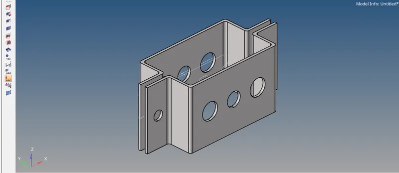
Fig :- 1 (Imported Model)
2. Delete the solids & unwanted lines using Delete->Solids->All & Delete->Lines->All.
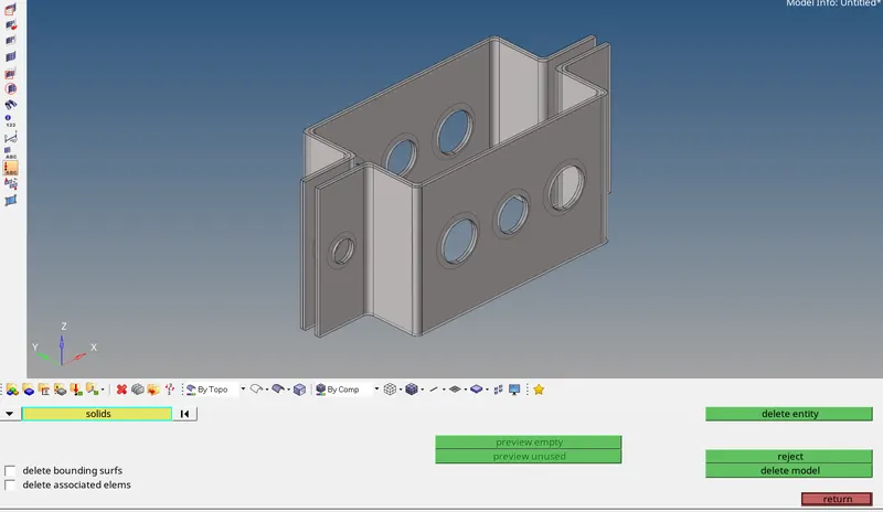
Fig :- 2 (Solids & Lines removal)
3. Extract mid-surface for both the brackets by using Geometry->Midsurface->Select Surface->Create.
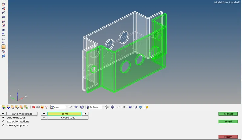
Fig :- 3.1 (Midsurfacing)
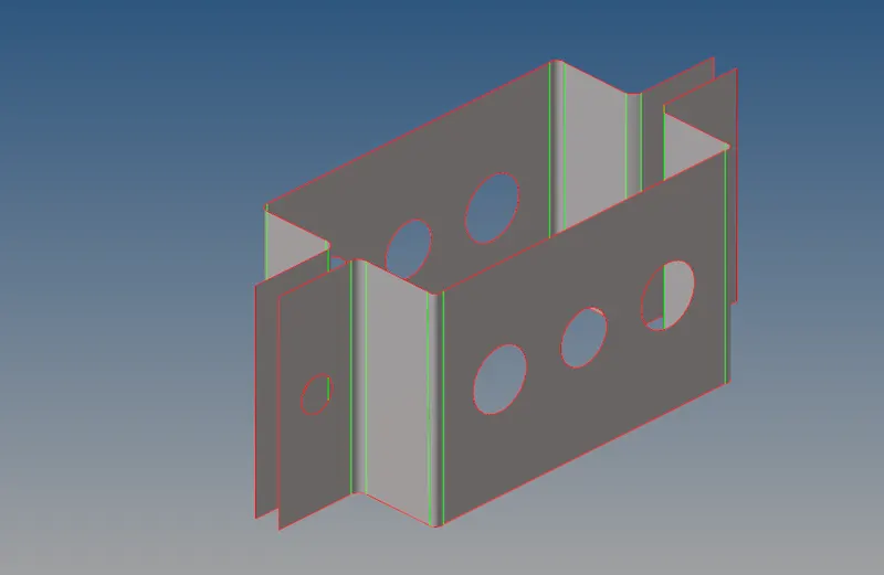
Fig :- 3.2 (Midsurface Extracted)
4. Add washer split of 5 units for all the holes by using Geometry->Quick Edit->washer split->line selection->create.
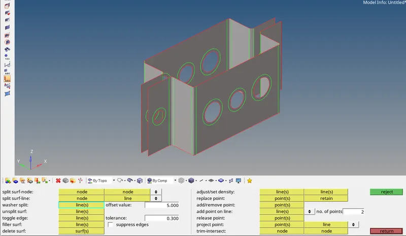
Fig :- 4 (Washer split addition)
5. Maintain separate component, material & property for both the brackets.
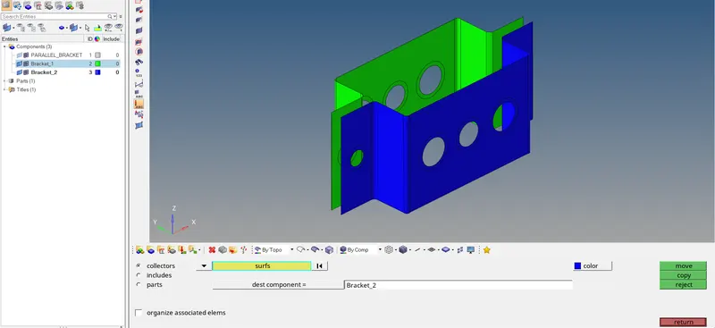
Fig :- 5 (Property, material & component)
6. Generate 2D mesh with element size of 5 units using 2D->Automesh->Surface Selection->Mesh or press F12 key as a short cut.
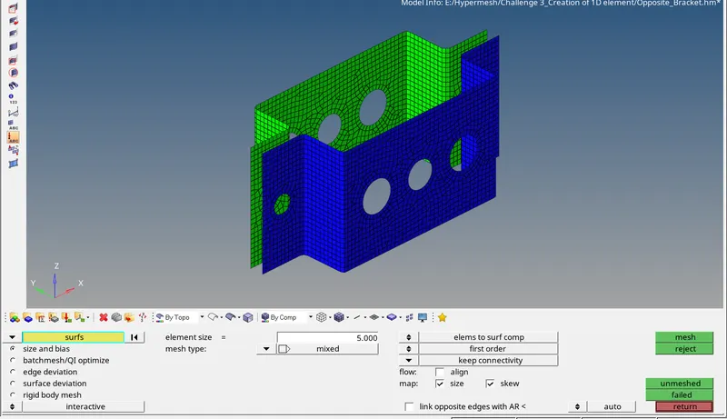
Fig :- 6.1 (2-D Surface Meshing)
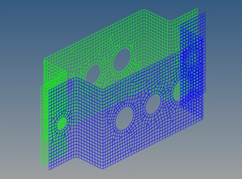
Fig :- 6.2 (Final FE of the component)
7. Create rigid links for all the nodes at the holes on both the brackets.
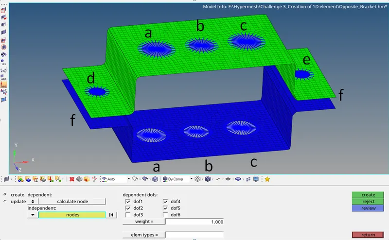
Fig :- 7.1 (Rigid Body Elements)
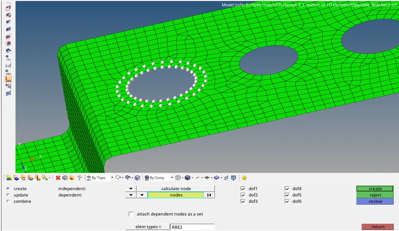
Fig :- 7.2 (RBE2 link for washer surface)
At point "a", implement RBE2 link with all DOF.
Create rigid body element by 1D->Rigids->Nodes selection (washer surface nodes by path)->Create.
Similarly create RBE2 links at point "a", "d", "e" & "f" on both the brackets.
Implement RBE3 link at point "b" with all DOF & point "c" with only X and Y DOF.
Create rigid body element by 1D->Rbe3->Nodes Selection (Washer surface nodes by path)->Create.
Create links on both the brackets.
8. Create 1D element Rod, Beam & Bar cross-sections by 1D->Hyperbeam->Standard Section->Create.
For point a, create Rod element cross section as shown in Fig 8.1
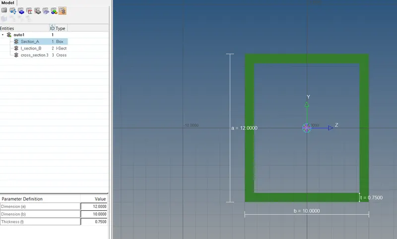
Fig :- 8.1 (Rod Element cross section for point a)
For point b, create I-Beam element cross section as shown in Fig 8.2
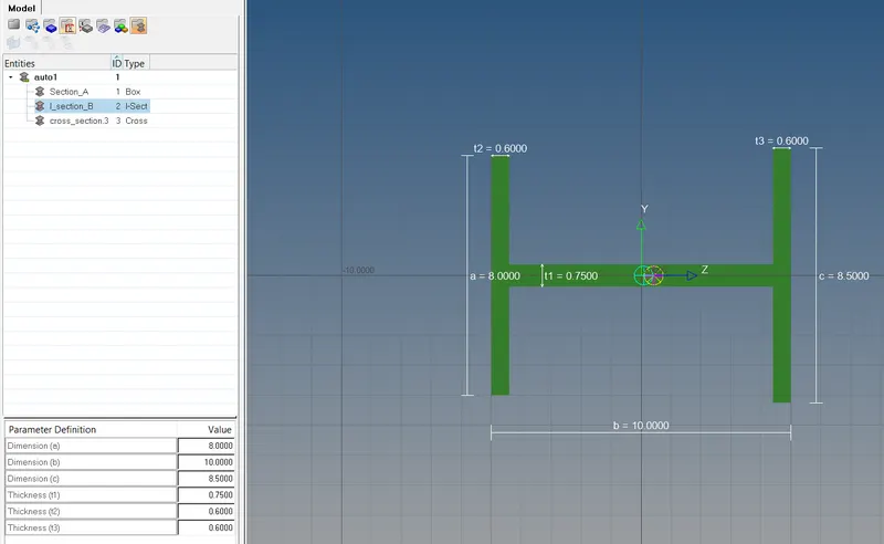
Fig :- 8.2 (I-Beam Element cross section for point b)
For point c, create Bar element cross section as shown in Fig 8.3
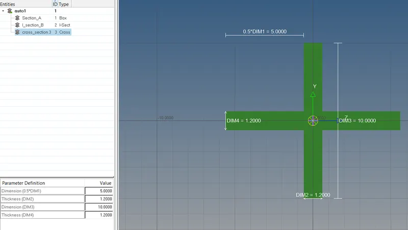
Fig :- 8.3 (Bar Element cross section for point c)
9. Create 1D element as follows,
At point "a", create Rod element as shown in Fig 9.1, by 1D->Rods->Node Selection (RBE2 master node on both brackets)->Create.
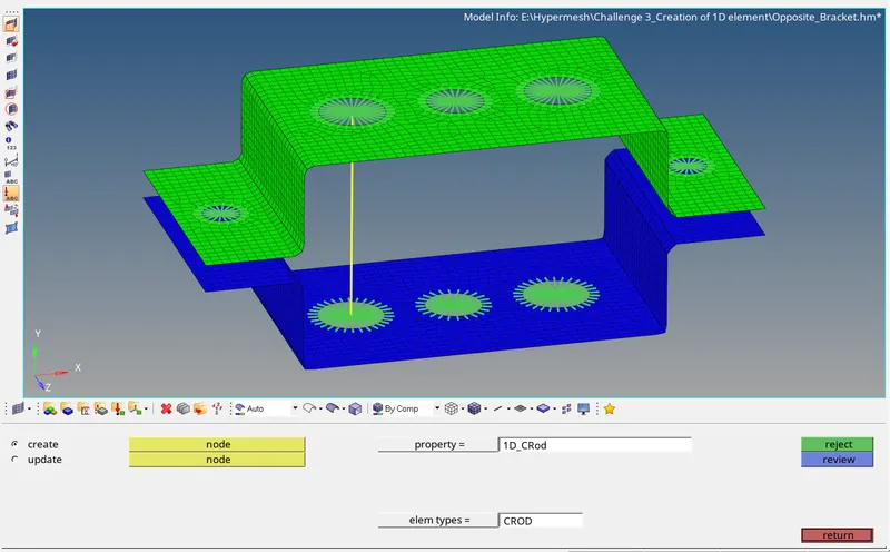
Fig :- 9.1 (Rod Element creation at a)
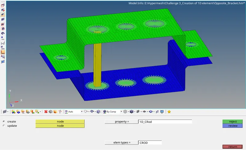
Fig :- 9.2 (1D detail element representation of Rod element)
Similarly create I-Beam element at point "b" and Bar element at point "c".
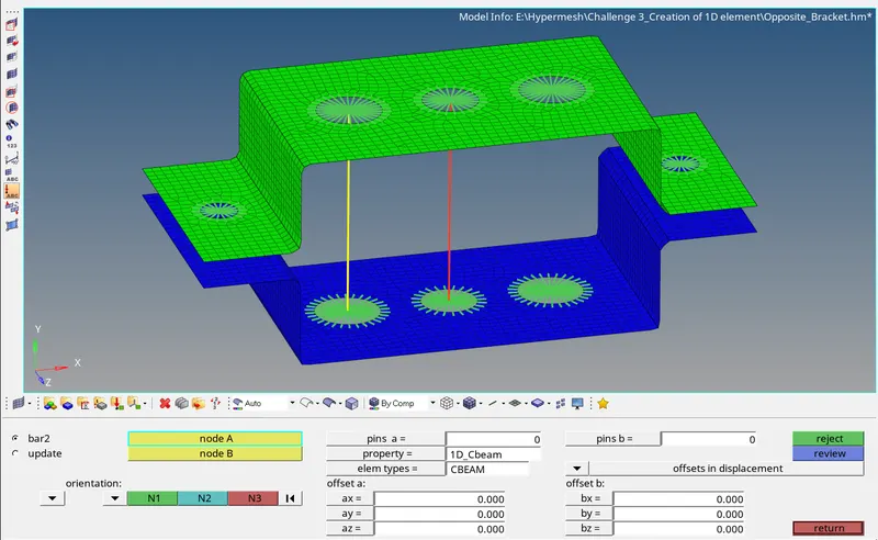
Fig :- 9.3 (I-Beam Element creation at b)
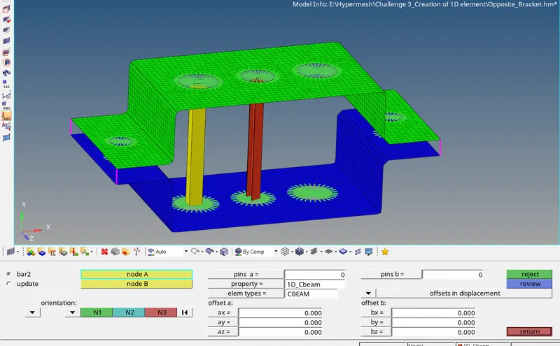
Fig :- 9.4 (1D detail element representation of I-Beam element)
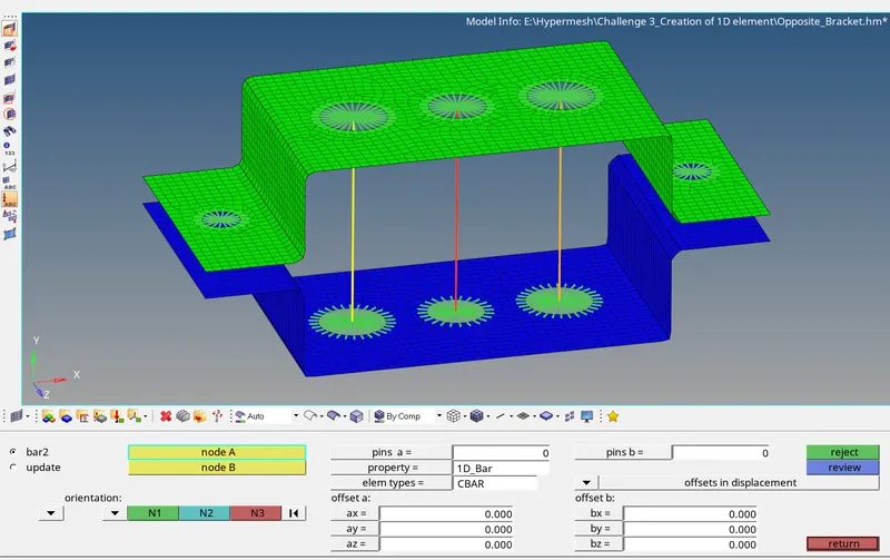
Fig :- 9.5 (Bar Element creation at c)
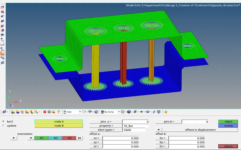
Fig :- 9.6 (1D detail element representation of Bar element)
10. At point "d", "e" and "f" apply 10 units of mass on the master node of the RBE2 element by 1D->Masses->Node Selection->Mass=10->Create.
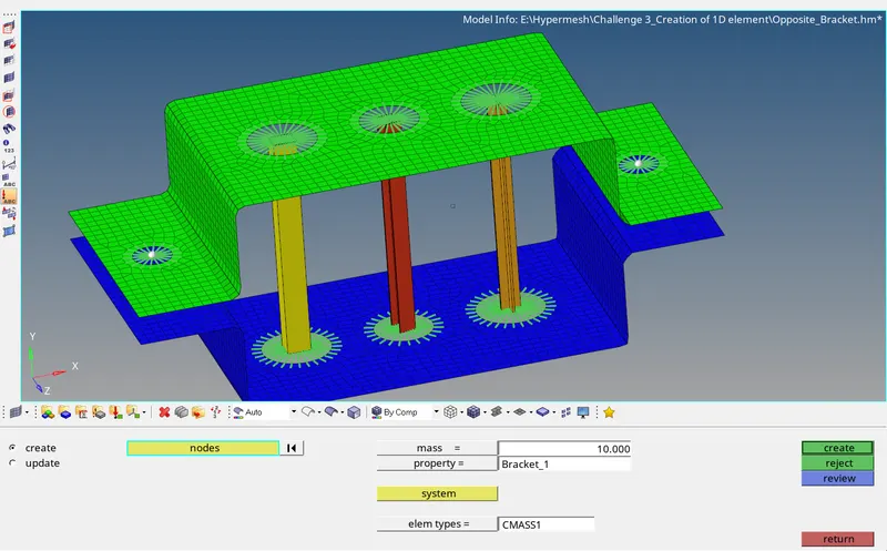
Fig :- 10 (Mass application on Master node of RBE2)
11. Create spring connection between the brackets by 1D->Springs->Node Selection->check dof2->element type=CELAS1->Create.
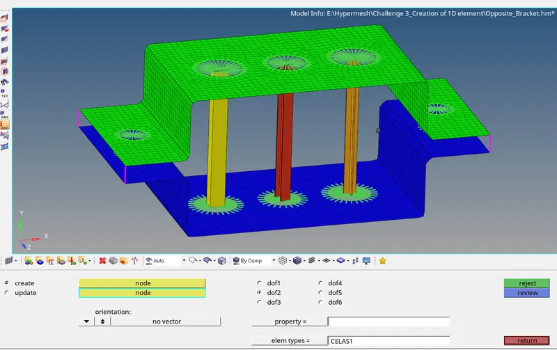
Fig :- 11 (Spring connection between brackets)
Outcome :-
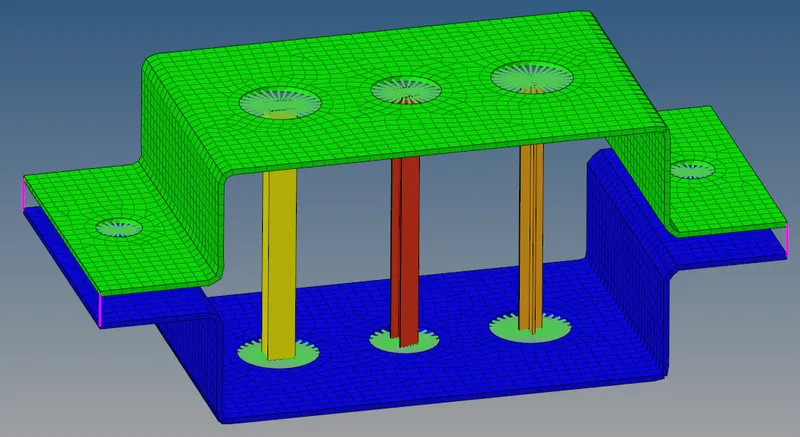
The below show figure shows the 2D detail element representation of the bracket after meshing and connection.
Learning :-
- Midsurfacing.
- Addition of washer split.
- 2D meshing.
- RBE2 & RBE3 connection.
- 1D Rod, Beam & Bar cross section.
- 1D element creation.
- Mass application.
- Spring Connection.
Result :-
The given model is imported to workspace, geometry clean-up is performed, mid surface is extracted, 2D meshing is performed, rigid body connection applied, 1D element created, mass applied and Spring element connected as per the given values.