Week 4.1: Project - Steady state simulation of flow over a throttle body
Aim:
To run Steady state simulation for the flow over a throttle body using converge.
Objectives:
-
Post process the results and show pressure and velocity contours.
-
Show the mesh (i.e surface with edges).
-
Show the plots for pressure, velocity, mass flow rate and total cell count.
Introduction:
The throttle body is an important part of your air intake system that controls the air flowing into your engine. It's located between your air intake and engine manifold where fresh air is pulled into the engine for the combustion process.
Model:
Case Setup:
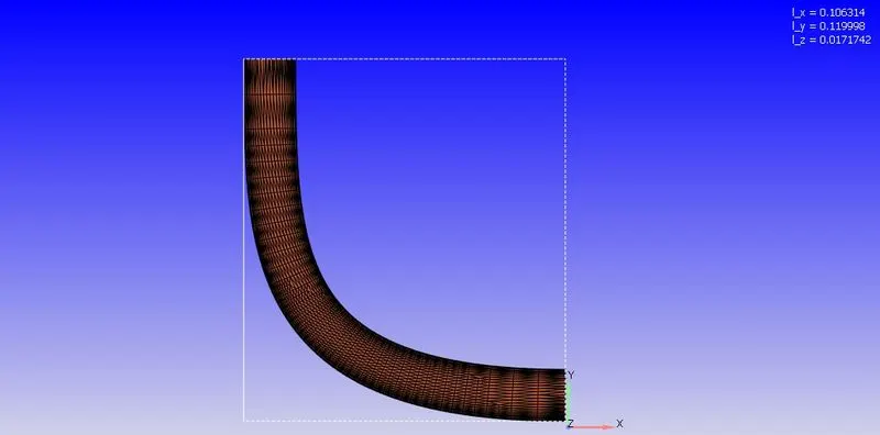
1) A geometry for the throttle flow is imported in converge studio.
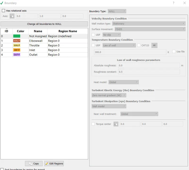
2) The necessary boundary conditions are defined.
3)The necessary steps are then followed in setting up the case where materials, simulation parameters, initial conditions, physical models etc are all specified.
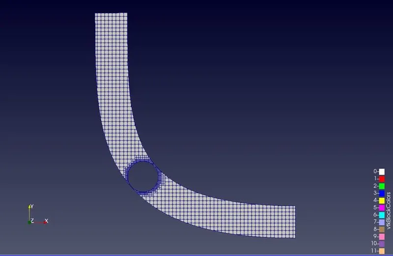
4) Base gride size & embedding is also specified
The boundary conditions are applied to the surfaces as follows:
Inlet :
Pressure:150000 Pa
Outlet :
Pressure:100000 Pa
Elbow:
Wall
Law of wall
Throttle:
Wall
Law of wall
Geometry:
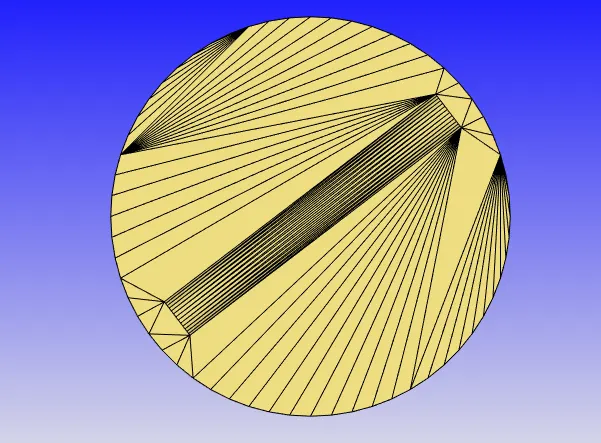
Throttle:
Mesh:
Gride size:
dx-dy-dz=2e-3
Embedding:
Scale :2
Embedding layers: 2
Contours:
Velocity contour:
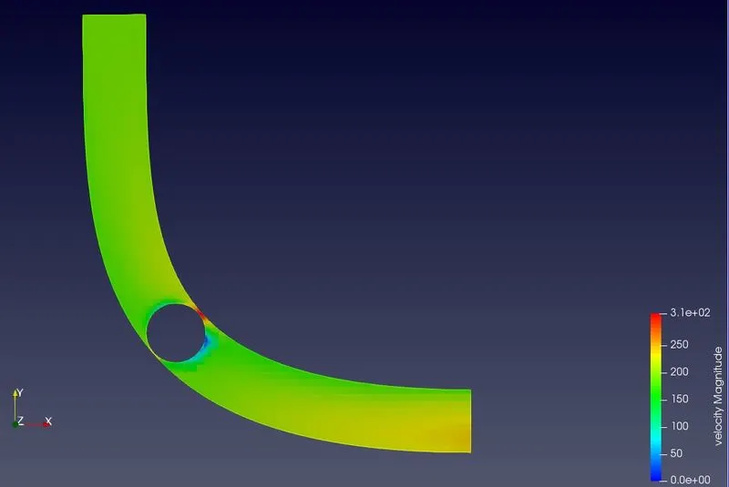
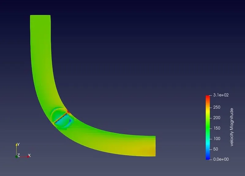
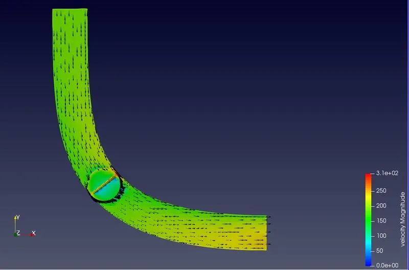
The maximum velocity of 310 m/s is predicted near the gap between the throttle and the elbow wall which is due to the reduced flow area at this section; also lowest velocity is recorded behind the valve where the flow is obstructed by the valve.
Velocity Vector:
Pressure contour:
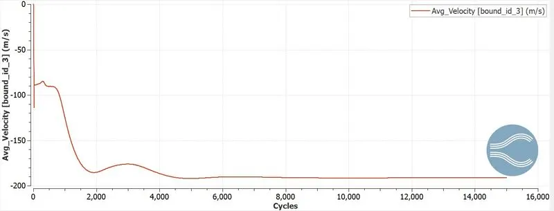
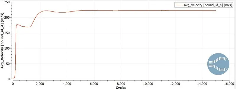
Plots:
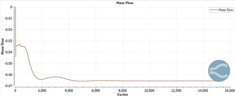
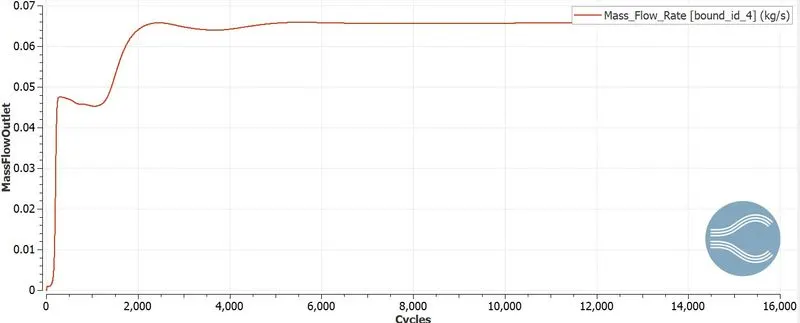
Massflow:
Inlet MassFlow:
Outlet MassFlow:
Inlet AvgVelocity:
 Inlet Outlet AvgVelocity:
Pressure:
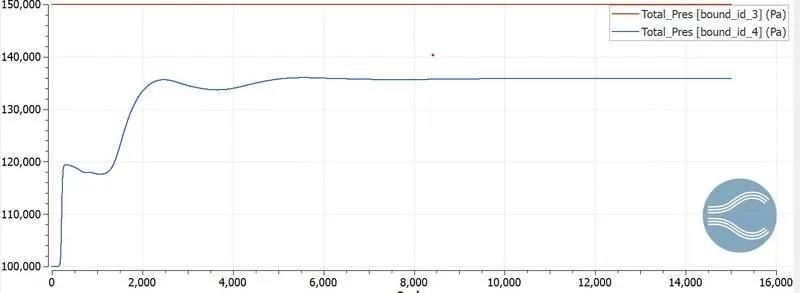
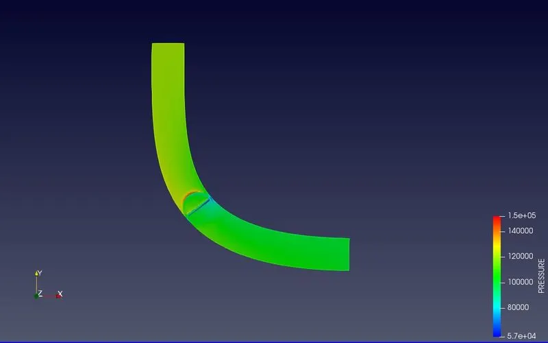
pressure contour -The side of the valve which faces the flow experiences the highest pressure of 1.5 Bar and the section between the throttle and elbow wall recorded the lowest pressure of 0.59 Bar.
Totalcells:
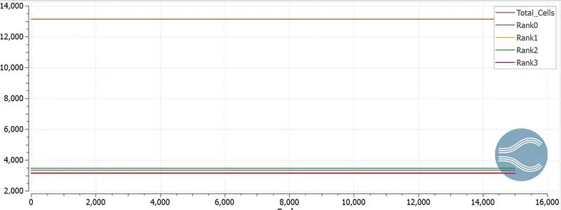
The total cell count can be predicted from above graph.
Conclusion:
Thus the Steady state simulation for the flow over a throttle body using converge is done.