Week 4.1: Project - Steady state simulation of flow over a throttle body
Geometry:
The geometry of the elbow is cleaned and patched so that the geometry is used to run the steady state stimulation is run through the elbow with throttle.
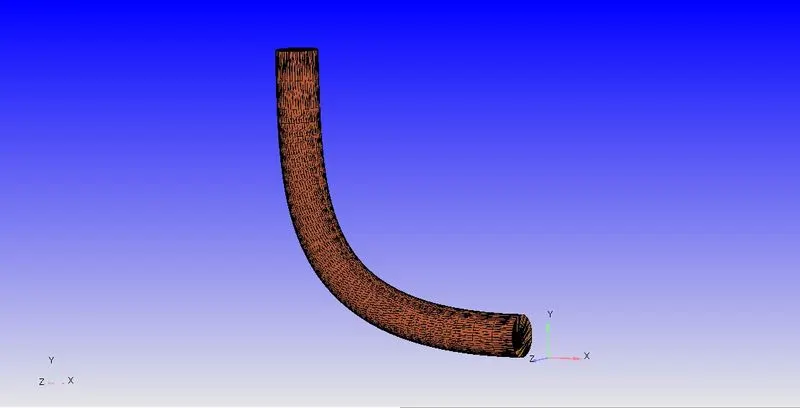
Throttle geometry top:
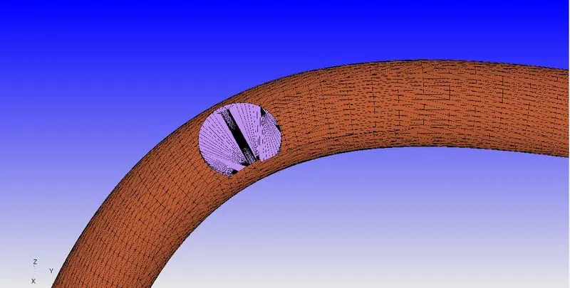
throttle geometry through inlet:
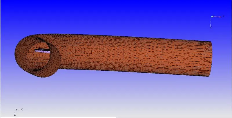
Once the geometry is cleaned and patched, the case setup is done. The stimualtion type is selected, boundary condition, region and meshing is also done. Then the code is run in CYGWIN command prompt. Later the post processed result is viewed through Paraview.
Mesh:
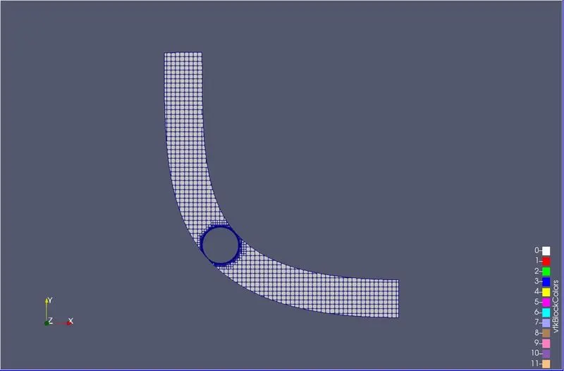
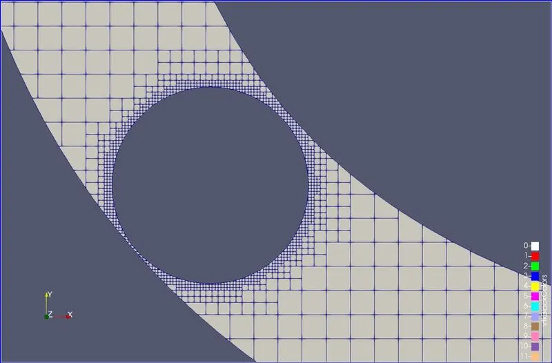
Embedded mesh;
Results:
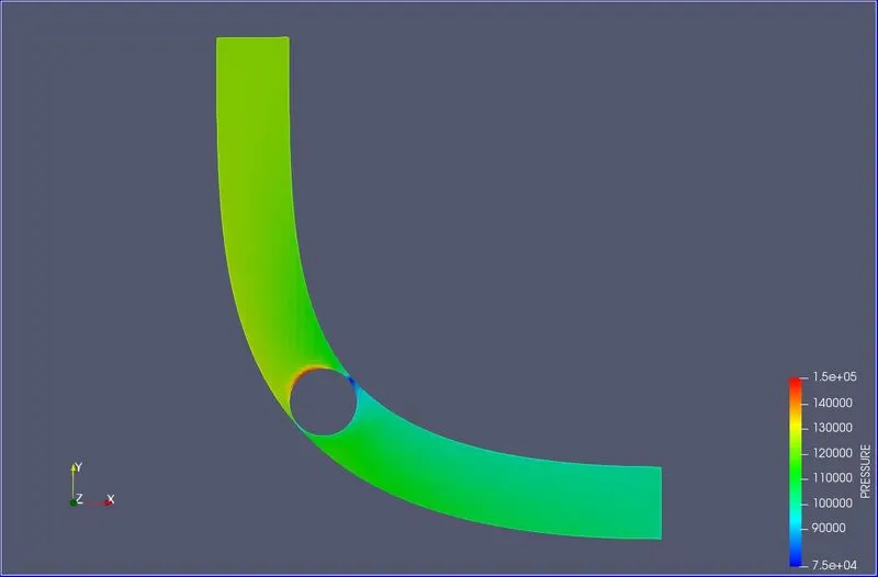
Pressure contour:
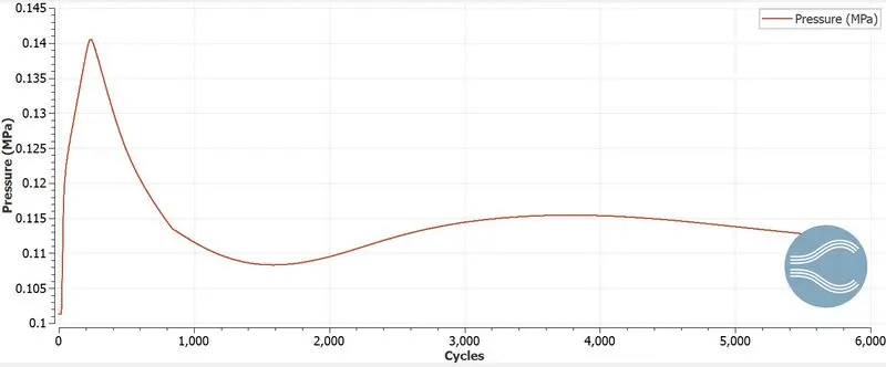
Pressure plot:
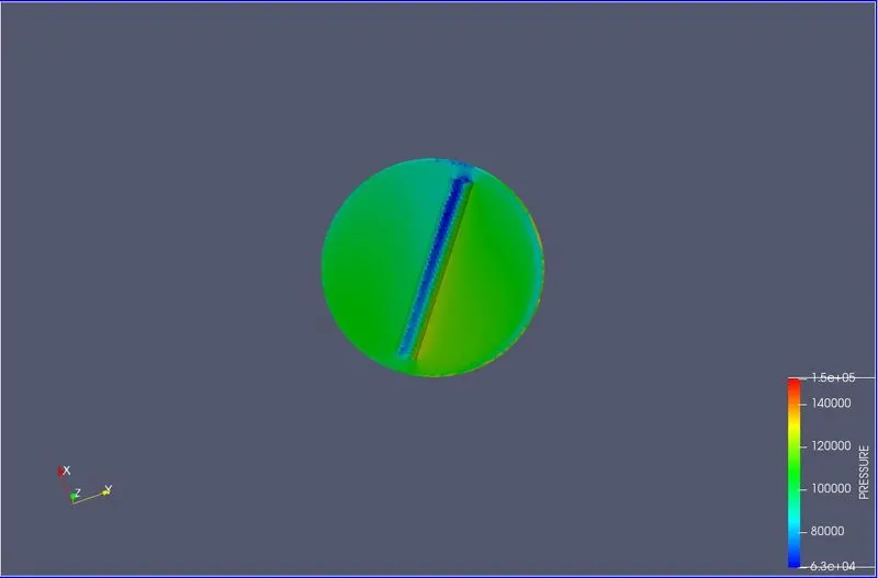
Pressure at throttle:
Pressure Animation:
Velocity contour:
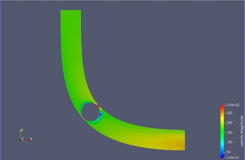
Velocity plot:
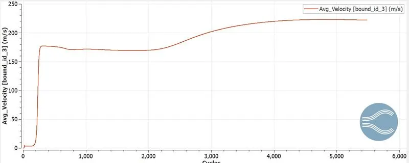
Velocity at throttle:
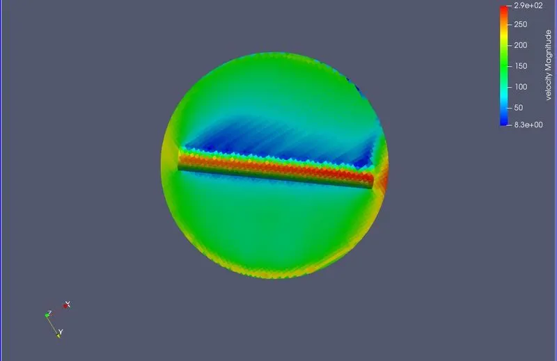
Velocity Vector slice:
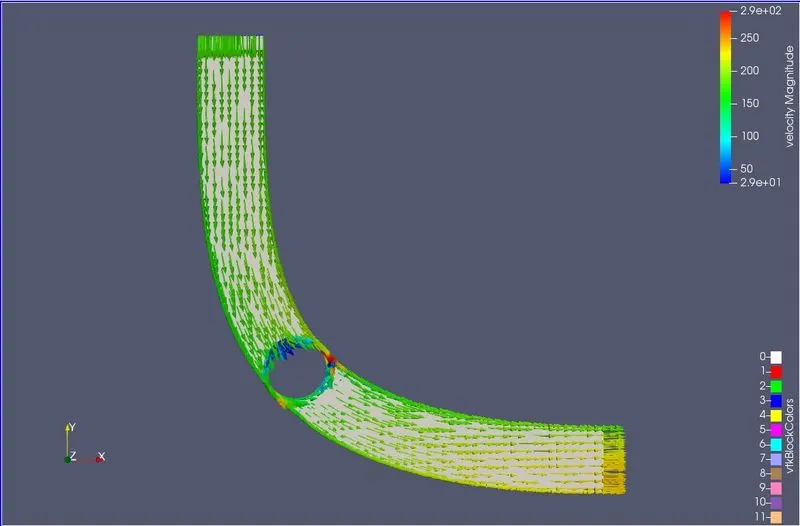
Velocity vector through elbow:
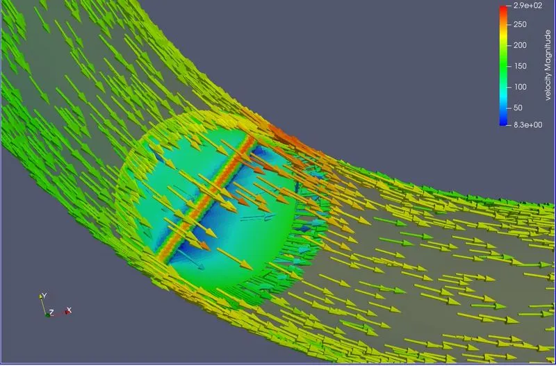
Velocity Animation:
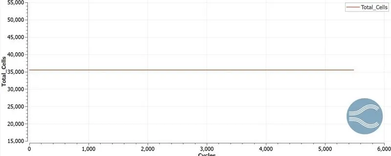
Total cell count plot:
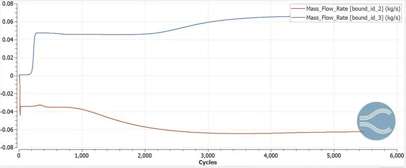
Mass Flow rate plot:
Inference:
From the steady-state stimulation done, the results show the Velocity and Pressure controur and plot are very clean that how the flow stimulates over the elbow. Since the throttle doesnot have contact with the surface with the elbow. The velocity is increased as the mass flow rate is same with the change in area of flow, the reduced area increases the velocity. The vectors, plots and animation is better resulted to study the stimualtion which is helpful understanding the result of the post processed data. Eventhough there is increase in velocity at the throttle region, the pressure contour results are different due to the precense of throttle.