Week 3 Verification of Weld Joints
VERIFICATION OF WELD JOINTS
OBJECTIVE:
To simulate three different types of welding using three different weld materials - Stainless steel, aluminium alloy and bronze and to determine the Directional Deformation and equivalent strain experienced in the component.
PROCEDURE:
- Create a new static structural simulation module
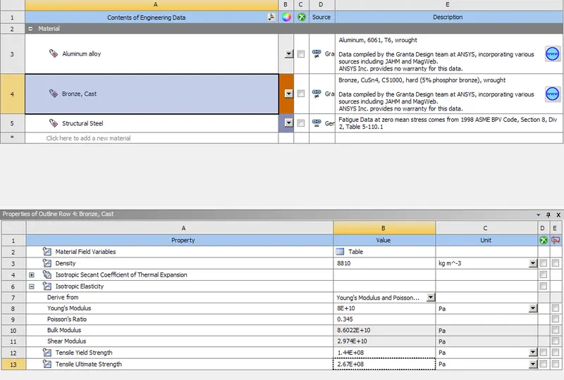
- Import the required material from the engineering data. Since the aluminium and bronze material data are not found the following mechanical properties can be used to recreate them.
- Finall all three materials are added to the database
- Import the Parasolid part file onto spaceclaim
- Open the model or setup module and set units
CASE 1: Stainless steel for both weldments and plates
- Rename the solid parts and contact regions to user convenience
- Makes sure all the models - incl. plates, ribs and weldments are assigned stainless steel as the material type
- select the important contact regions i.e between plates and ribs and set them to frictional with a frictional coeff of 0.2
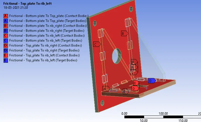
- The analysis parameters like large deflection and solver type are specified.
- In this case the entire load is acted on a single step with no increments.
- The model is fixed at the holes and a load of 15000N is applied on the rectangular slit portion along the Y axis
- Hence the directional deformation along Y axis is specified as the output requirements including equivalent stress and strain data.
- Mesh the model using sizing option with different target length for plates and rib features - 7mm for plates and 5mm for ribs
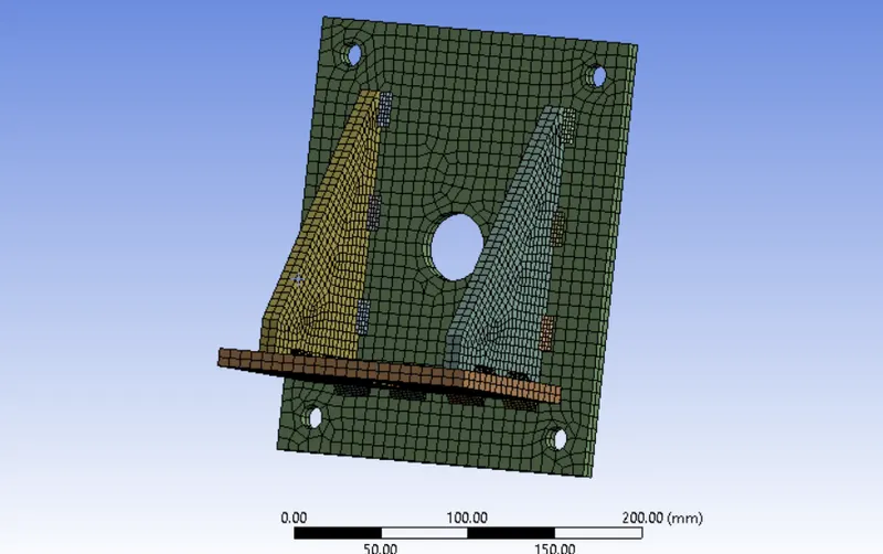
The following results were generated.
Equivalent stress
Equivalent strain
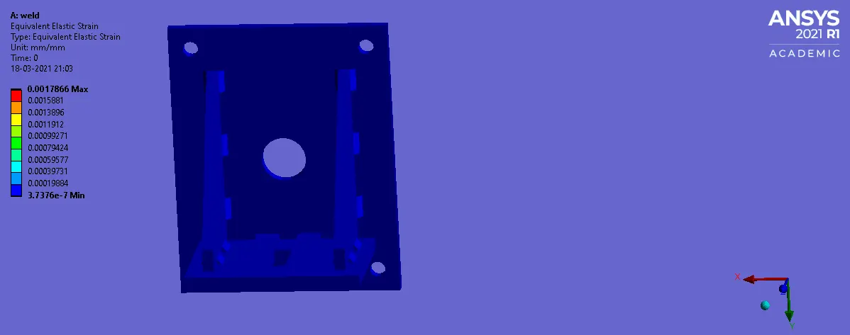
Directional deformation (Y)
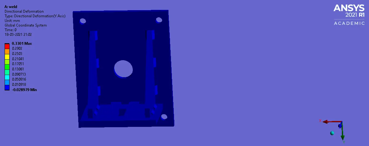
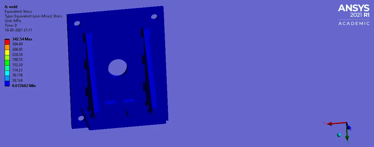
Stress at weldments
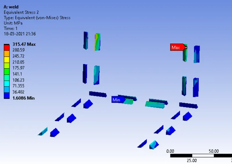
CASE 2: Weld material is aluminum alloy and plates are stainless steel
All the weldments were selected and the al alloy material is assigned while the plate and rib components were kept as stainless steel
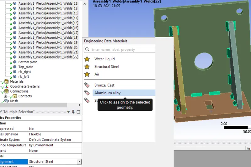
The following results were obtained,
Equivalent stress
Equivalent strain
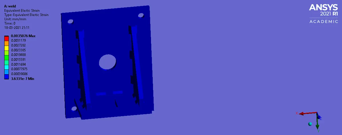
Directional deformation (Y)
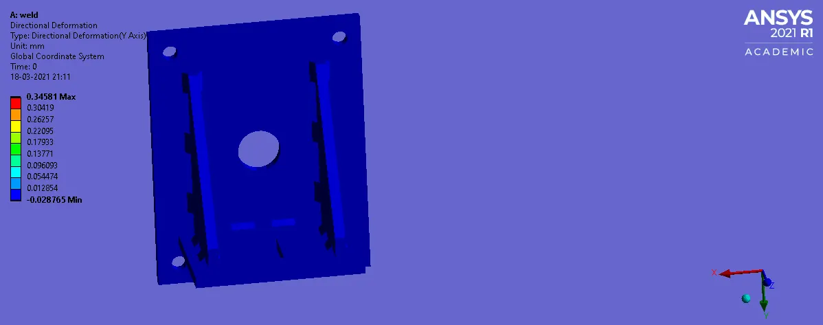
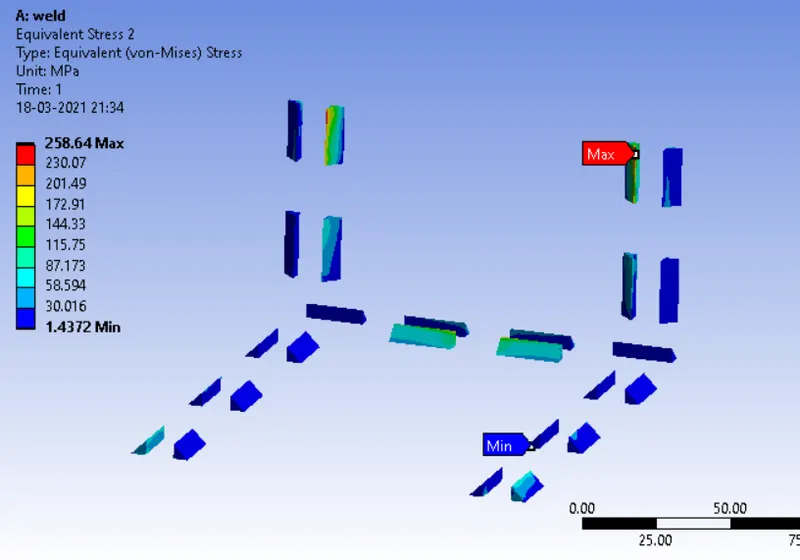
Stress at weldments
CASE 3:Bronze as the weld material and Stainless Steel to both plates and Copper to the ribs
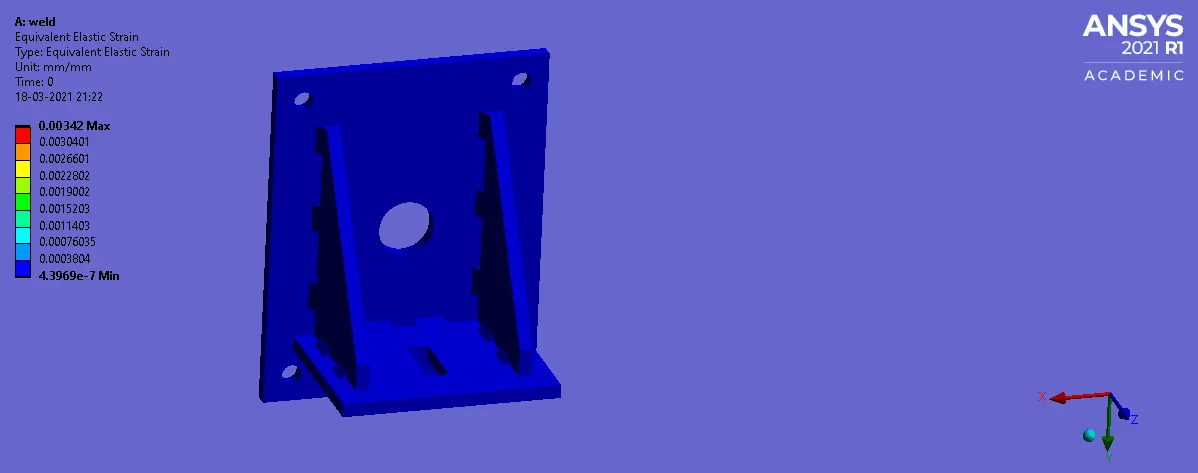
The following results were obtained
Equivalent stress
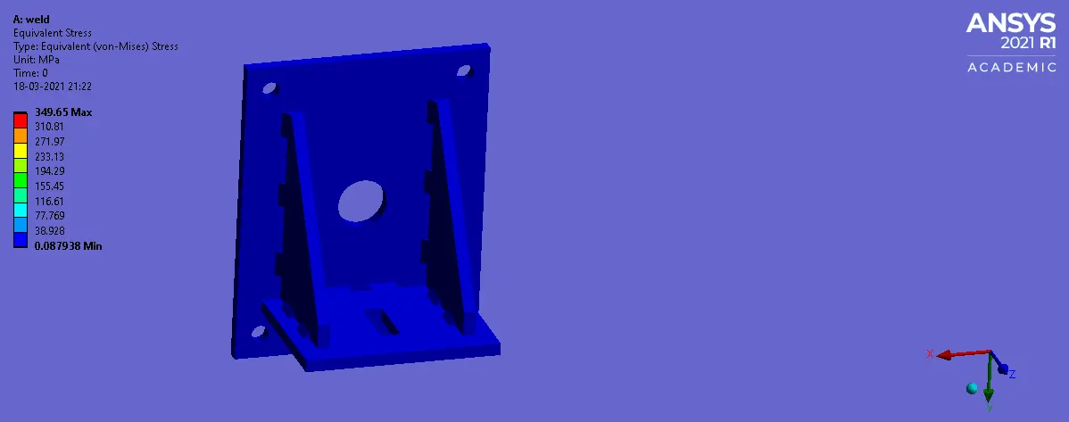
Equivalent strain
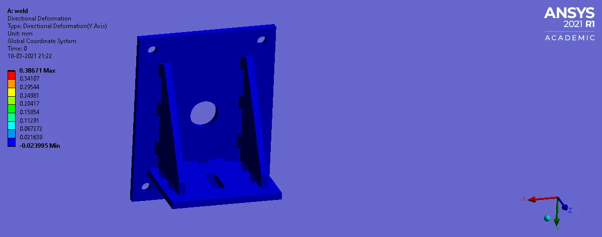
Directional deformation (Y)
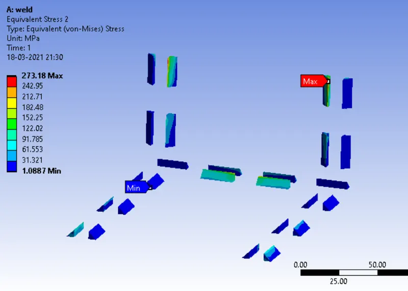
Stress at weldments
CONCLUSION:
Hence from the above results, we can conclude that the max stress generate is higher in case 3 with less or no change from case 1 and 2 apart from directional deformation. Similarly, the directional deformation is highest in case 3 at the region or plate where the loading is acted upon. Moreover, the weldment with the higher probability of failure is near the rib component and based on the material of weldments, the welds on case 1 are more susceptible to fracture.