Week 3 Sheet metal Bending challenge
Objective: In this study simulation of sheet metal bending has done. This study compares the results at different cases.
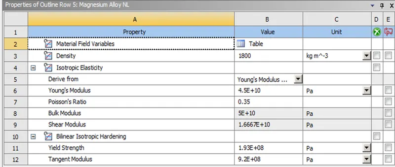
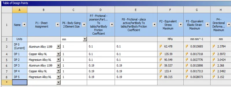
Case 1: Aluminium Alloy 1199, Copper Alloy NL, and Magnesium Alloy NL. Find out the Equivalent stress, Equivalent elastic strain, and Total Deformation in the Y direction and compare the results for the three materials.
Case 2: With the material as Aluminium Alloy, change the friction coefficient to 0.19 and run the analysis as mentioned in Case 1. Compare the results with that in case 1.
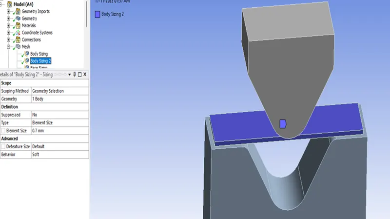
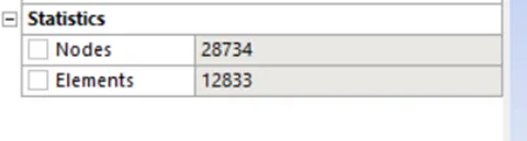
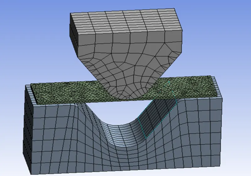
Case 3: Refine the mesh on the plate such that it doesn't cross the academic limit. With Aluminium alloy as material, run the analysis as in Case 1 and compare the results.
The outcomes results are Equivalent stress, strain, total deformation and This study is done in Ansys 2022
Introduction:
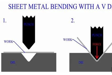
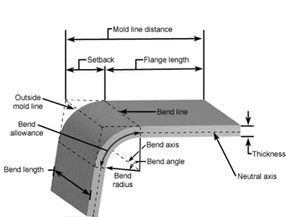
Metal bending is a process by which metal can be deformed when applying force to the subject, which causes it to bend at an angle and form the anticipated shape, which often results in it being in a 'V' or a 'U' shape. A press brake is a tool used in order to bend sheet metal and uses a punch and die to do this.
Procedure:
1.Geometry
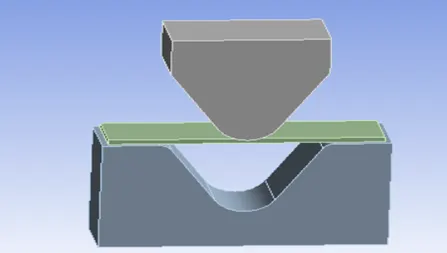
- Input the model as Step format in geometry
2.Material assignment
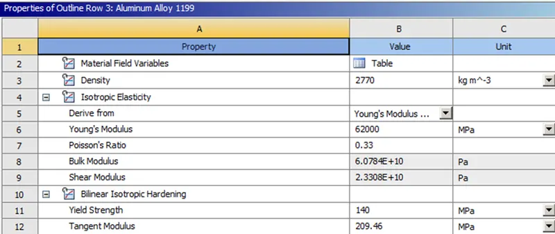
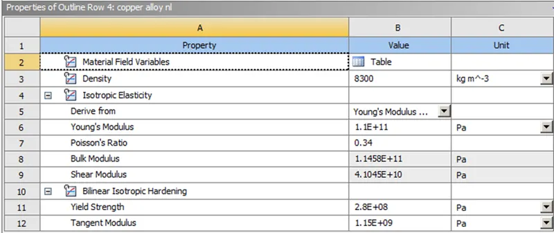
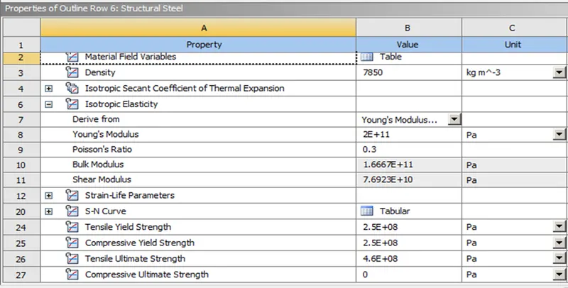
- Open Engineering Materials and select the required material.
- Stainless steel is used as material in ANSYS for die and punch and for sheet metal plate with different material but initially study is starting with Aluminum Alloy 1199 material.
3.Meshing
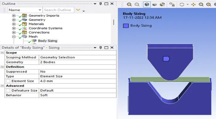
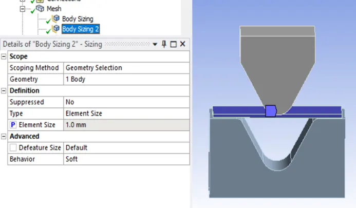
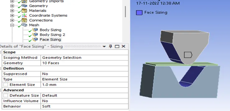
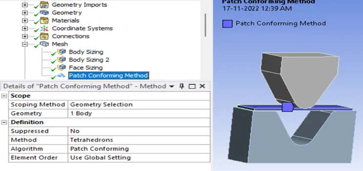
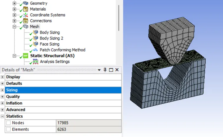
- For Meshing the body element size =4mm
4.Boundary condition
Connection
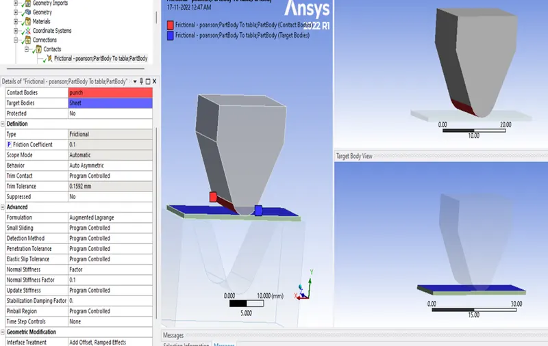
1.Contact creation
(a)
- Select the faces of gear teeth which will be in contact during simulation running
- Definition > type - Frictional
- Advanced > Formulation - Augmented Langrage
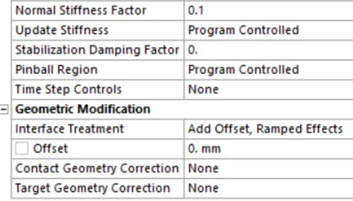
- Geometric Modification > Interface Treatment - Add offset Ramped effect
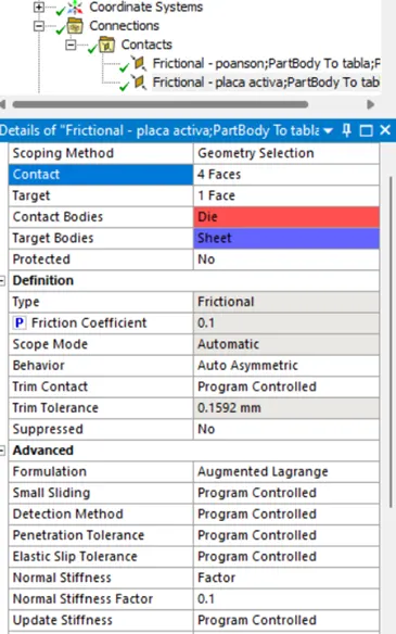
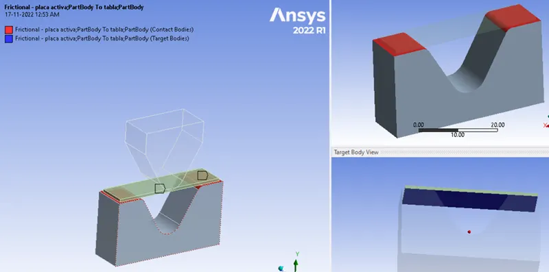
(b)
- Select the faces of gear teeth which will be in contact during simulation running
- Definition > type - Frictional
- Advanced > Formulation - Augmented Langrage
- Geometric Modification > Interface Treatment - Add offset Ramped effect
2.Analysis Setting
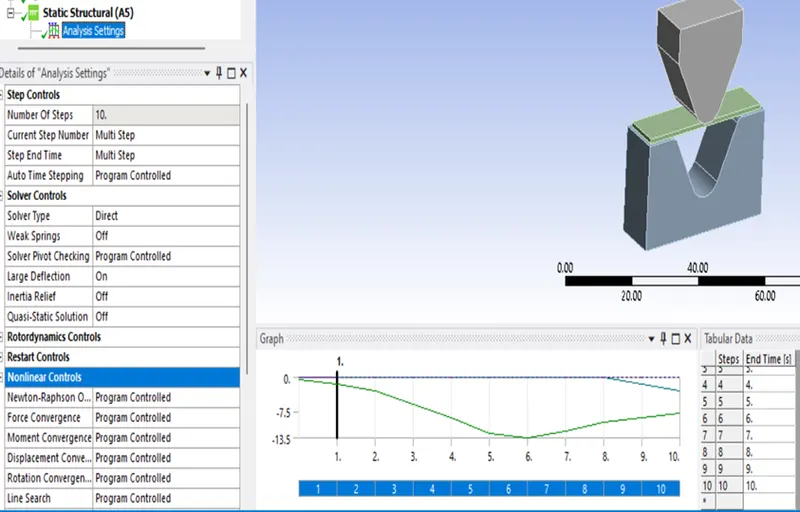
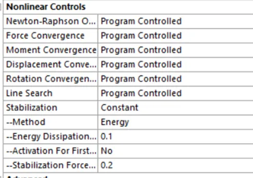
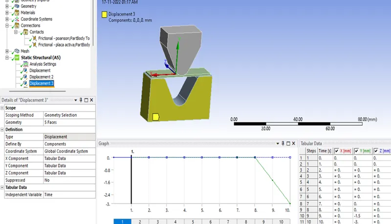
- (a) Displacement of punch (Insert by right click on analysis setting)
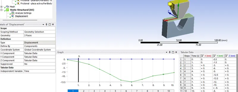
- (b) Displacement restriction of sheet two faces (Insert by right click on analysis setting)
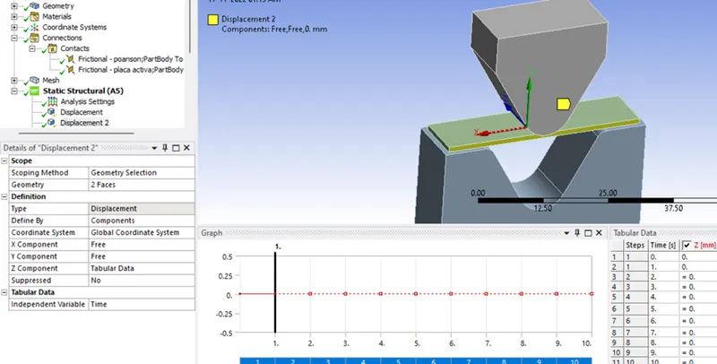
- (c) Displacement restriction of sheet two faces (Insert by right click on analysis setting)
Results (output):
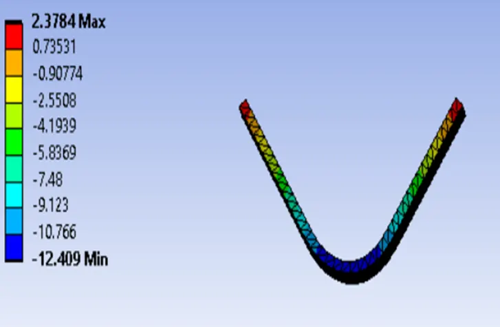
Directional deformation (In negative Y direction)
Max deformation= 12.409mm
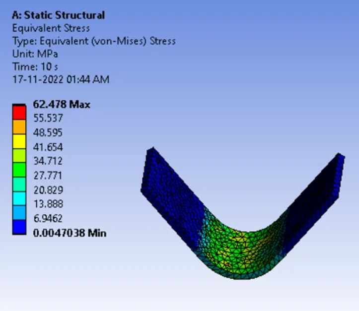
Stress
Max stress= 62.478Mpa
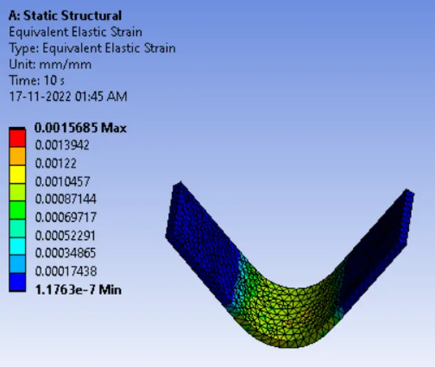
Strain
Max Strain =0.0015685 mm/mm
Now compare these results for different material condition by parametric study by selecting the P symbol as above results which will required for comparing
(Case1 and case 2 result out put)
Case 3 result output
Mesh element size 0.7mm of sheet metal plate
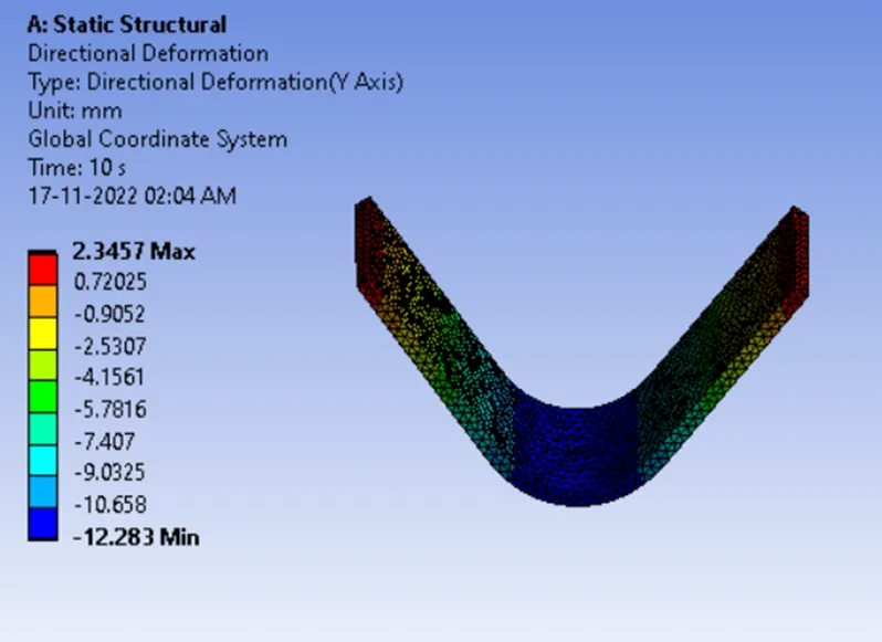
Directional deformation (In negative Y direction)
Max deformation= 12.283mm
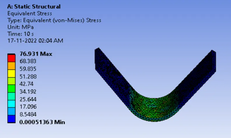
Stress (stress of whole product)
Max stress= 76.931Mpa
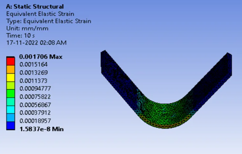
Strain (strain of whole product)
Max Strain =0.001706mm/mm
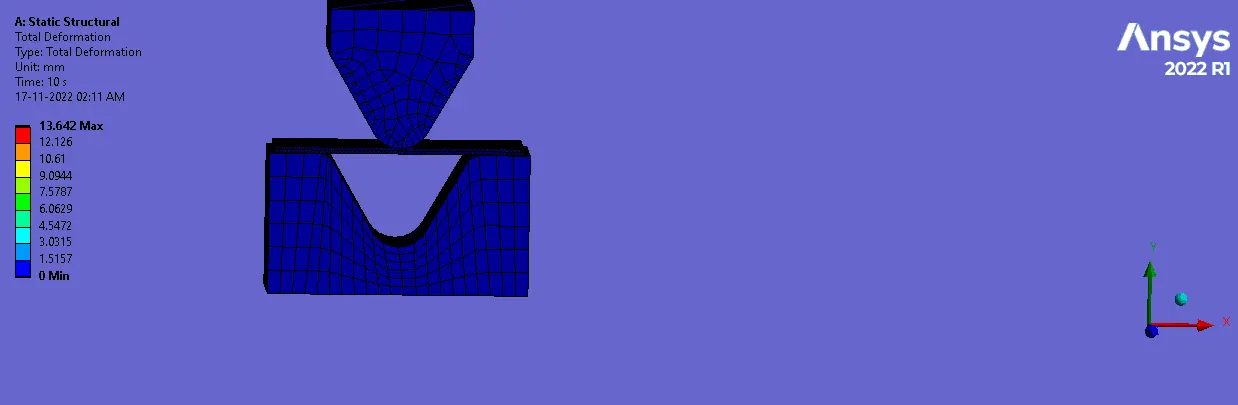
Whole setup animation
Conclusion:
By comparing the result, the study shows that in design with change of friction coefficient at 0.19 the equivalent stress of Aluminum 1199 has low stress value of approx. 59.5 Mpa compare to other. But by refining the mesh element size from 1mm to 0.7mm the equivalent stress increased of Aluminum 1199 of 76.931Mpa.