Week 3 - Geometry simplification of an Electronic enclosure assembly
AIM: To convert the given CAD model into ICEPAK object using ICEPAK commands in Space Claim .
INTRODUCTION: A CAD model is given which is a PCB circuit enclosed in an enclosure. We use Space Claim direct moduler to open the given model and Space Claim commands to manupulate the model and defeature the enclosure. We use the ICEPAK commands to convert the PCB assembly into ICEPAK objects and after the conversion of PCB assembly into ICEPAK object we perform some operations on the other objects to eliminate the objects which donot participate in the flow simulation and then convert the remaining enclosure into ICEPAK object. We use other options like Grille and openings to create grilles and opening on the enclosure which act as entry and exit to the air flow during simulation. After the conversion of whole assembly into ICEPAK object we open the converted model in the ICEPAK solver so that we can be sure that the conversion of the whole assembly has been done completely.
PROCEDURE:
MODEL IN SPACE CLAIM:
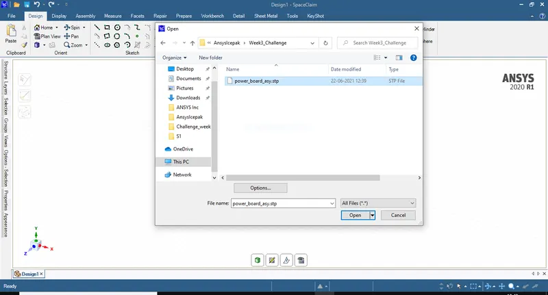
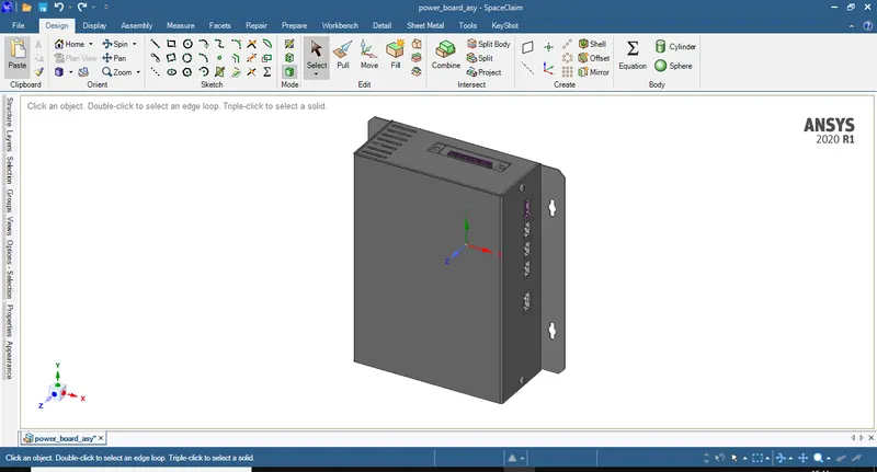
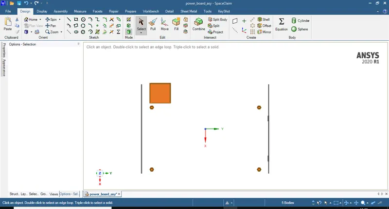
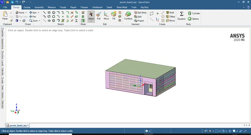
1. Open the Space Claim direct moduler and open the given CAD file. The assembly in Space Claim looks as shown in the figure below
2. Remove the extensions of the enclosure which donot participate in heat and flow analysis.
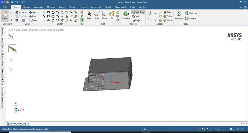
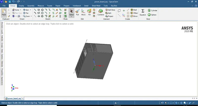
3. Remove the fillets by selecting the fillets and using delete.
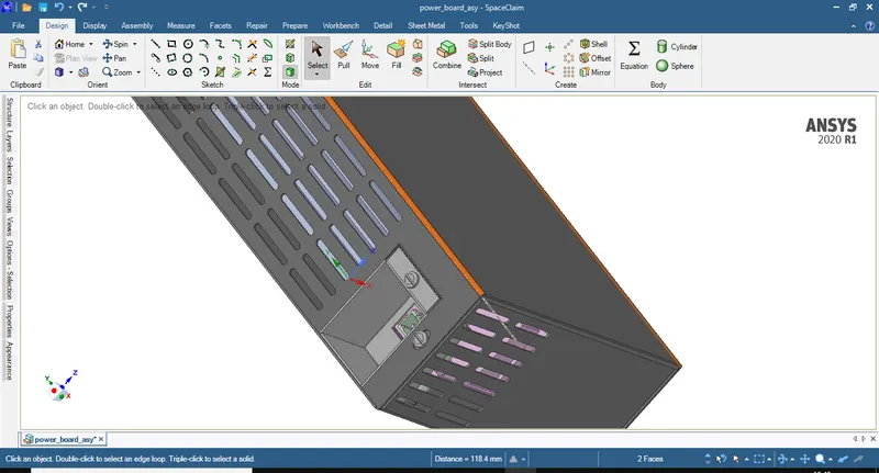
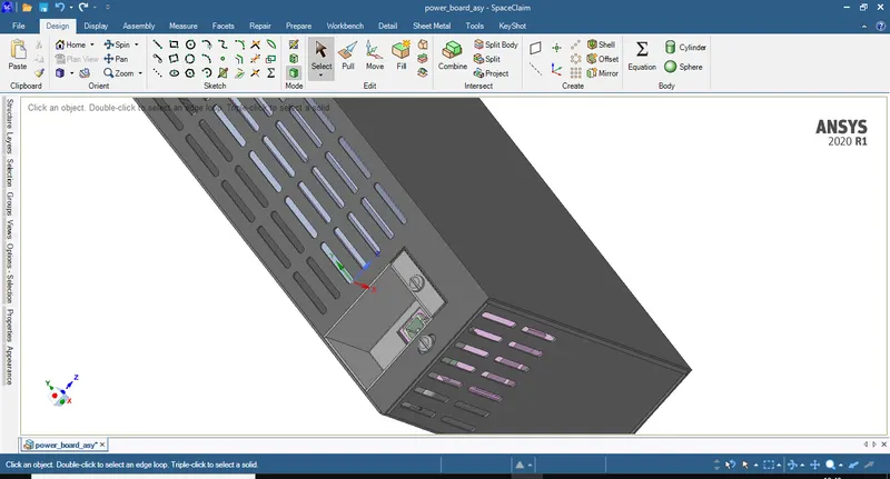
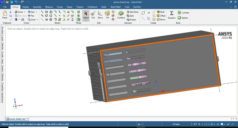
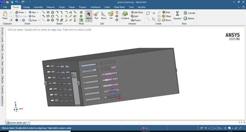
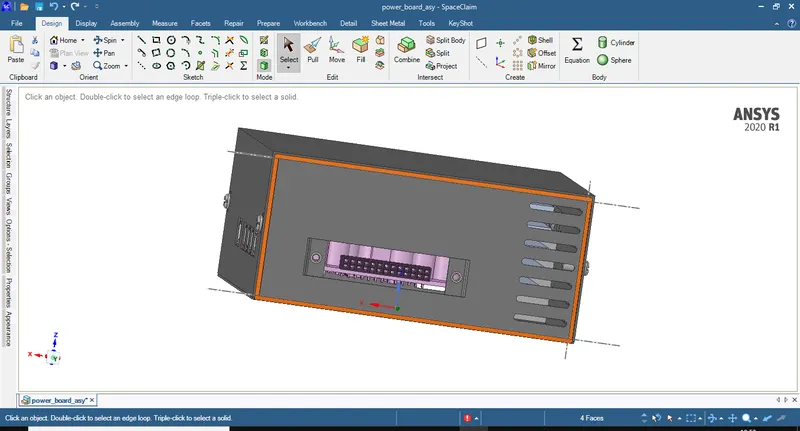
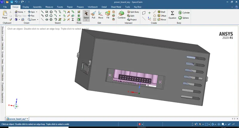
4. Hide the top of the enclosure by selecting it in the assembly tree and using visible command.
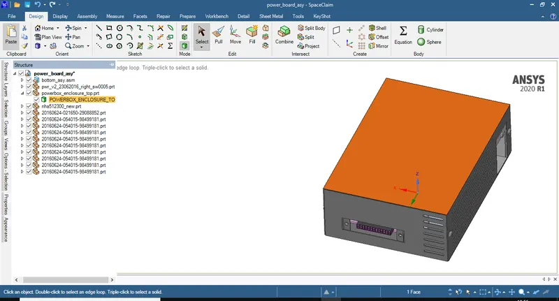
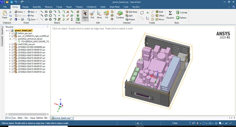
5. Select the bolts and nuts which donot participate in the flow and thermal analysis and remove them by using delete command.
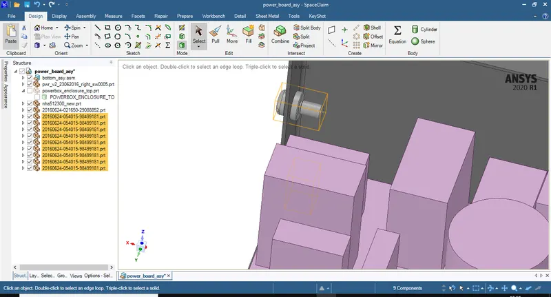
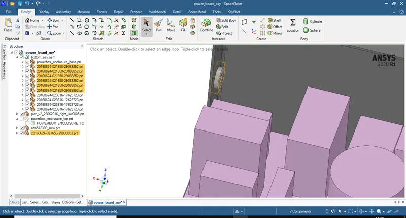
6. Delete the fillets inside of the enclosure.
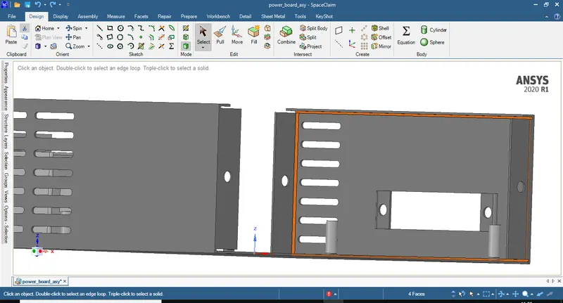
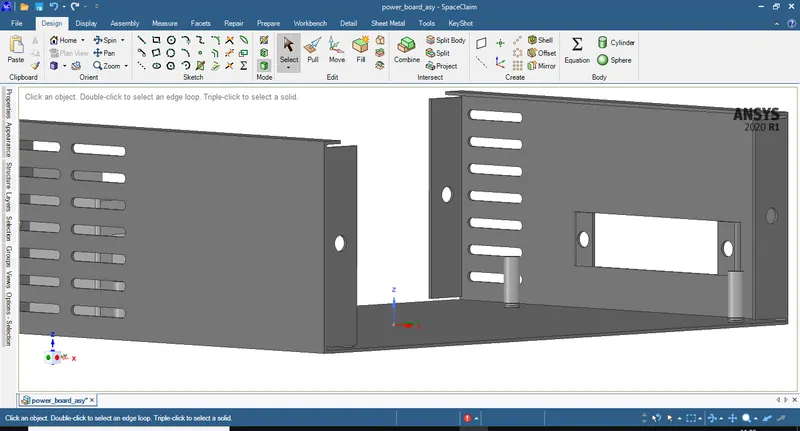
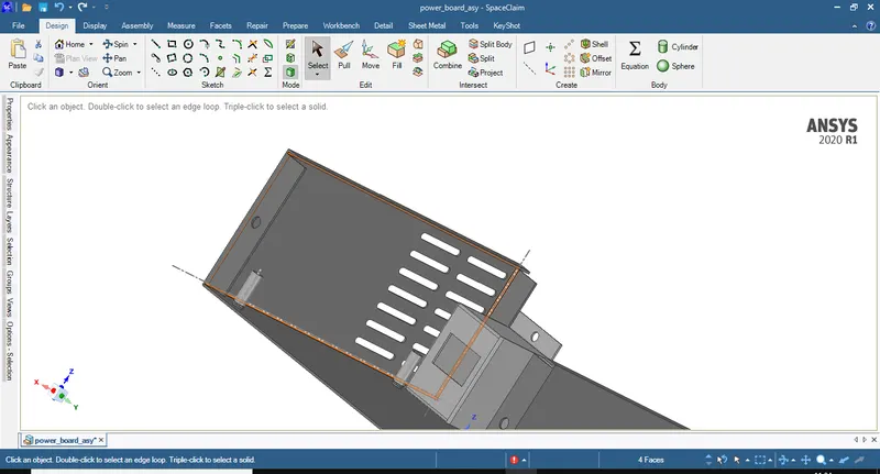
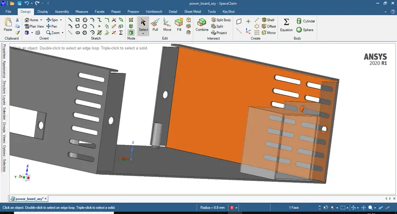
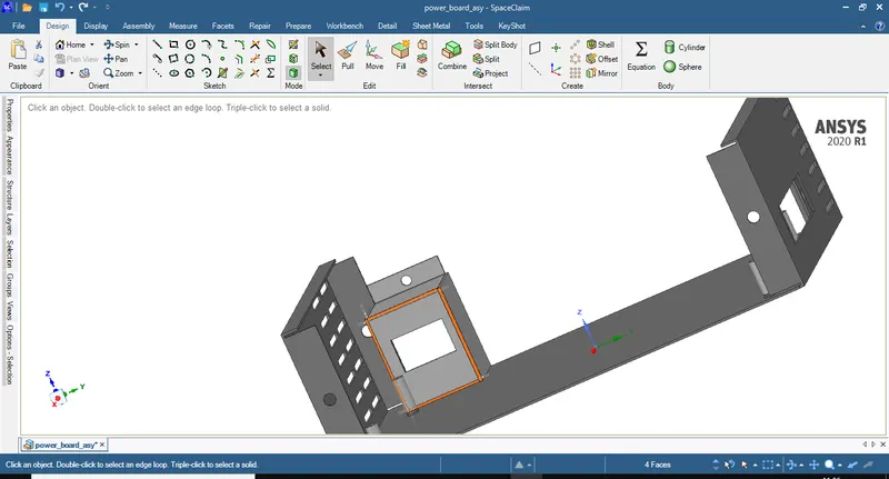
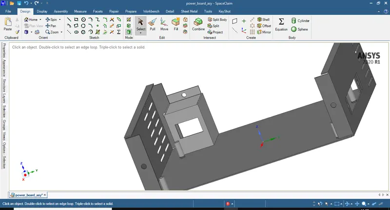
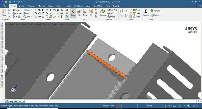
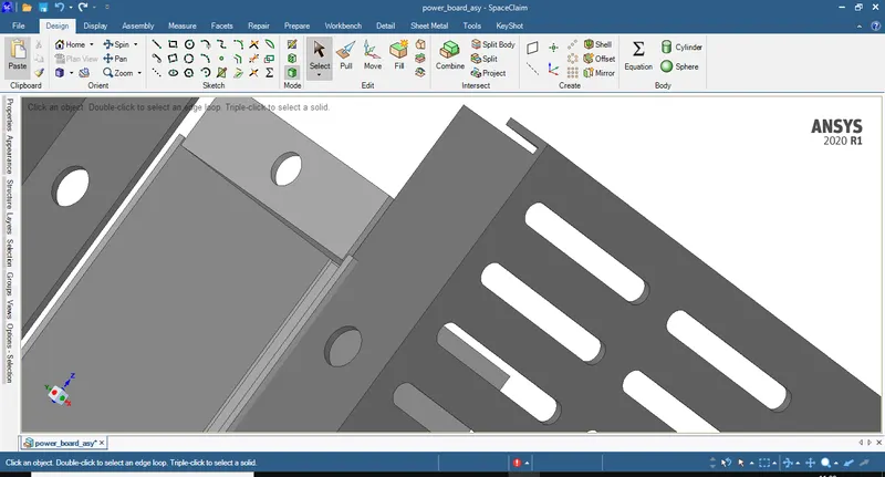
7. Make only the top of enclosure visible and delete the fillets.
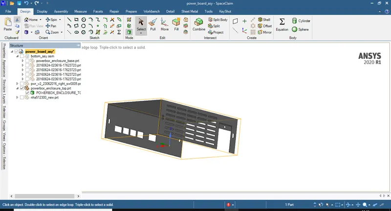
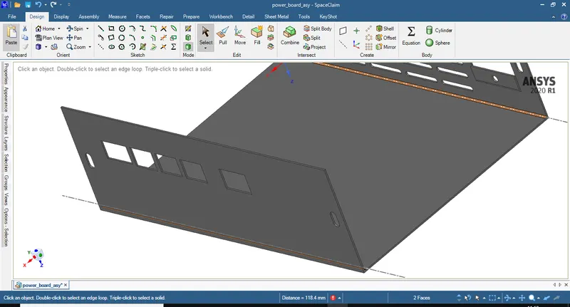
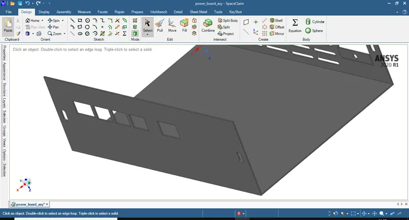
8. By using the fill command closs the bolt holes on the enclosure.
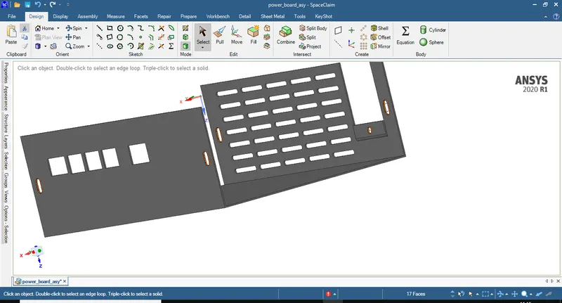
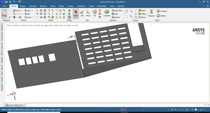
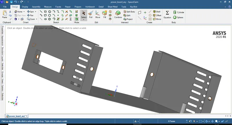
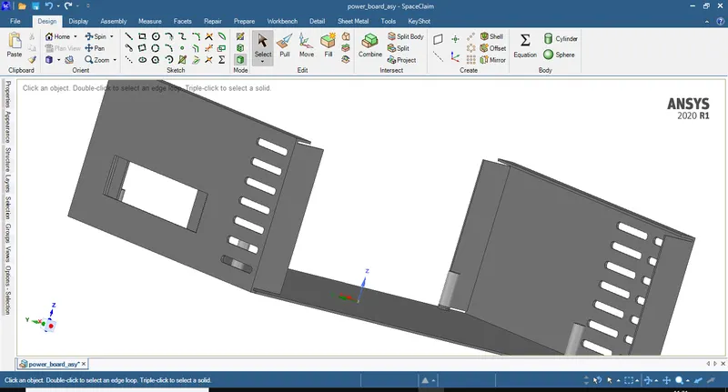
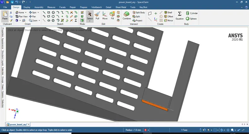
9. Delete the other remaining fillets if any.
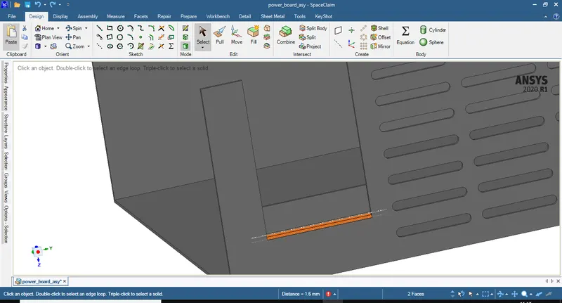
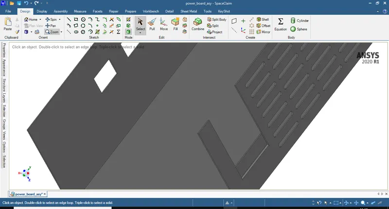
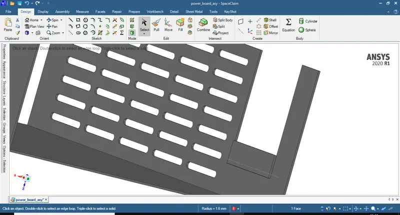
10. Using the pull command close the power socket hole in the enclosure.
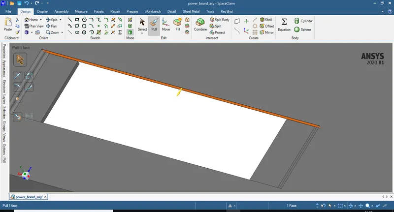
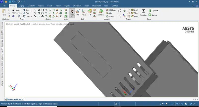
11. Open the PCB part by selecting the part in assembly tree and using open component command.
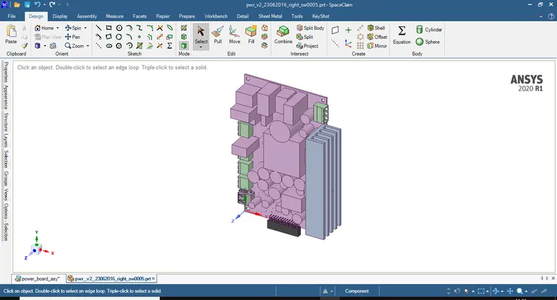
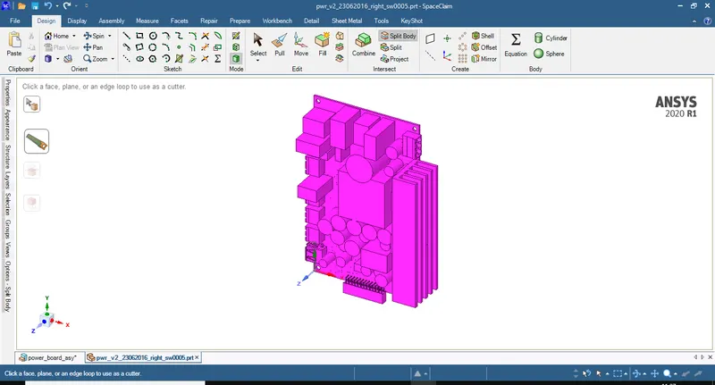
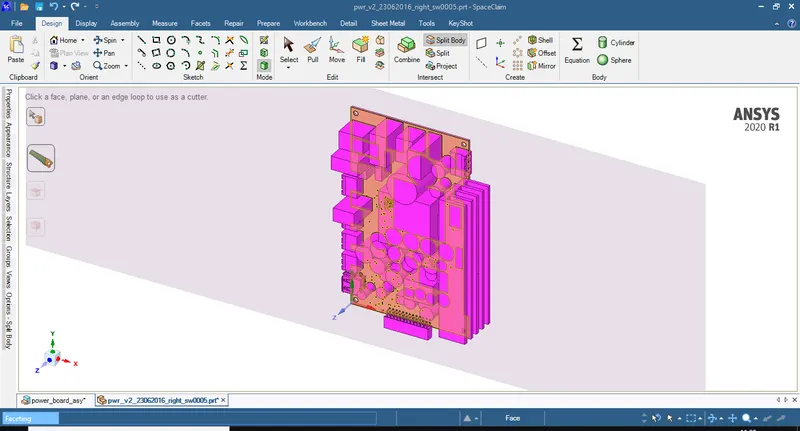
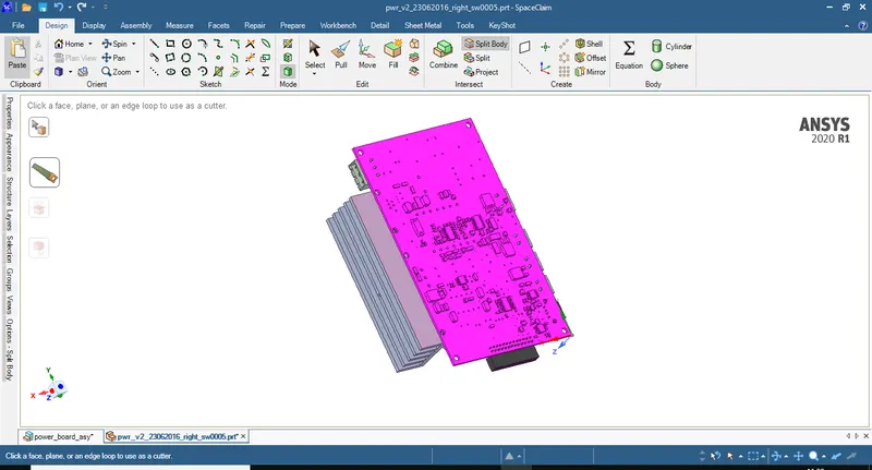
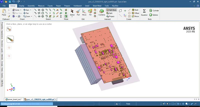
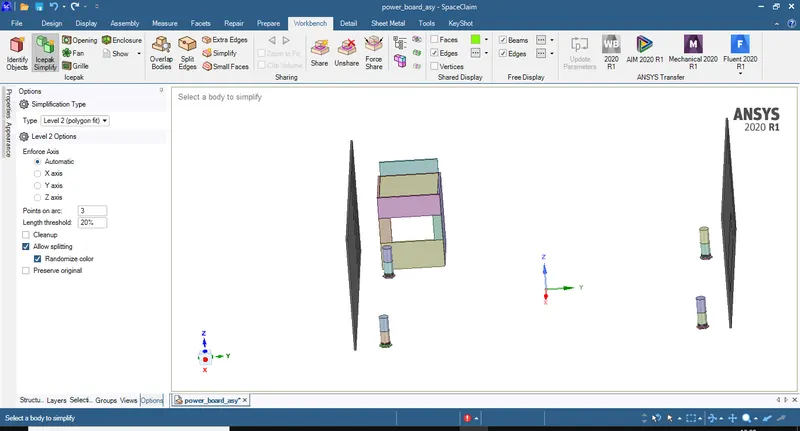
12. Using split body command and split the PCB assembly into different parts by selecting upper and lower surface of PCB as below
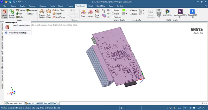
13. In the Workbench type select Identify Objects to convert CAD objects into ICEPAK objects.
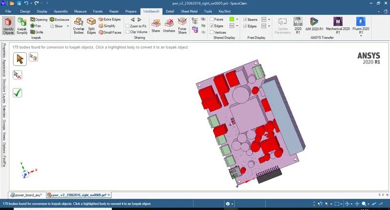
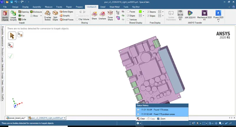
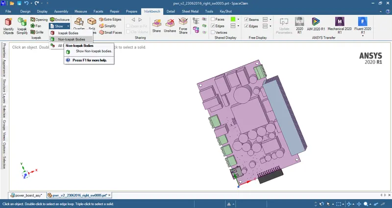
14. 179 CAD objects are now converted into ICEPAK objects. Select Non-Icepak objects from show option to see only the CAD objects that need to be converted to ICEPAK objects.
15.By using split body command the parts highlighted below are split using the planes as shown below.
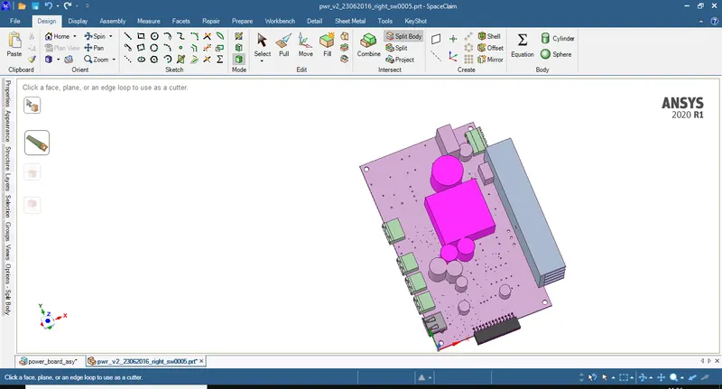
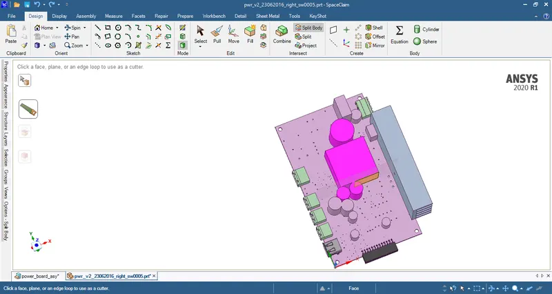
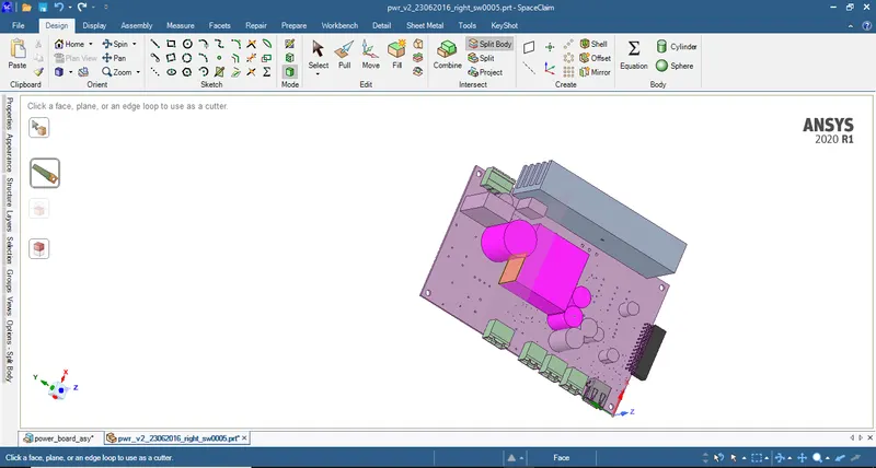
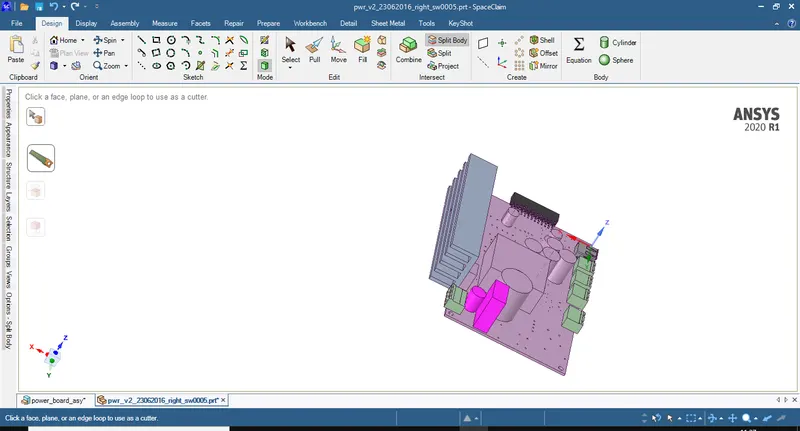
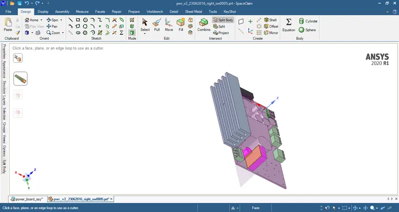
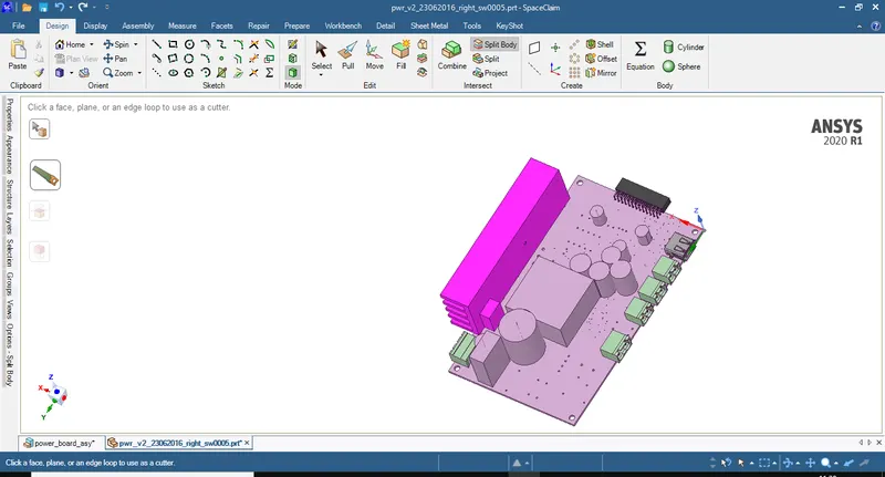
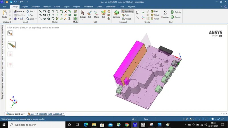
16. After splitting the bodies we can convert the below highlighted bodies into ICEPAK bodies.
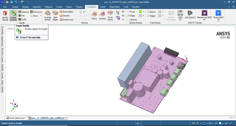
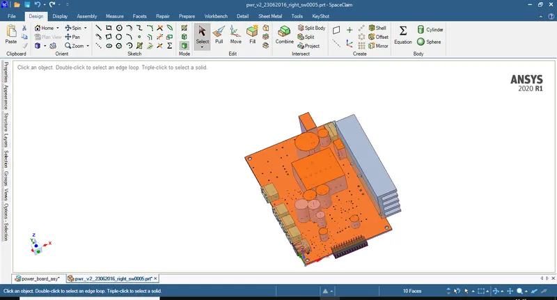
17. By using ICEPAK simplify command and level 1 option the above highlighted bodies are converted into ICEPAK objects and after conversion if we select non-ICEPAK objects option from show menu we can see the objects which are to converted as shown below.
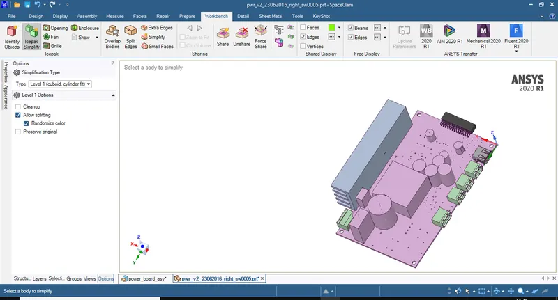
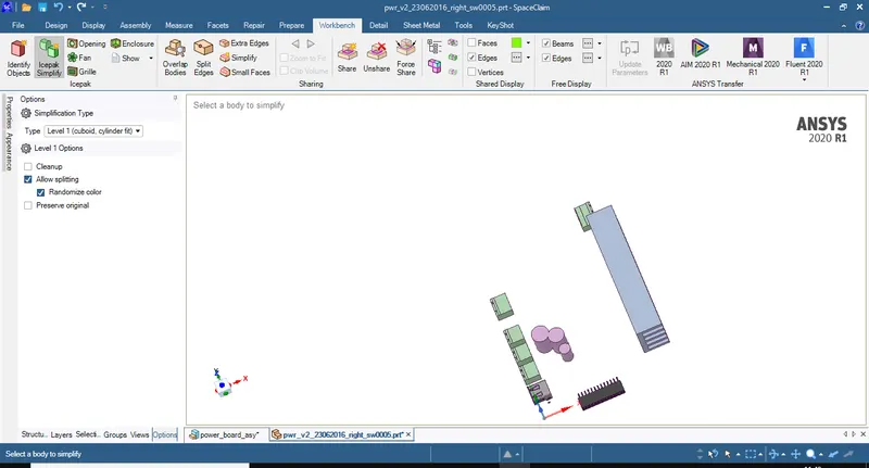
18. To convert the part which contains union of 3 cylinders into ICEPAK object we have to split them first. For that we draw lines joing intersection of cylinders as shown below.
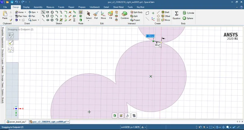
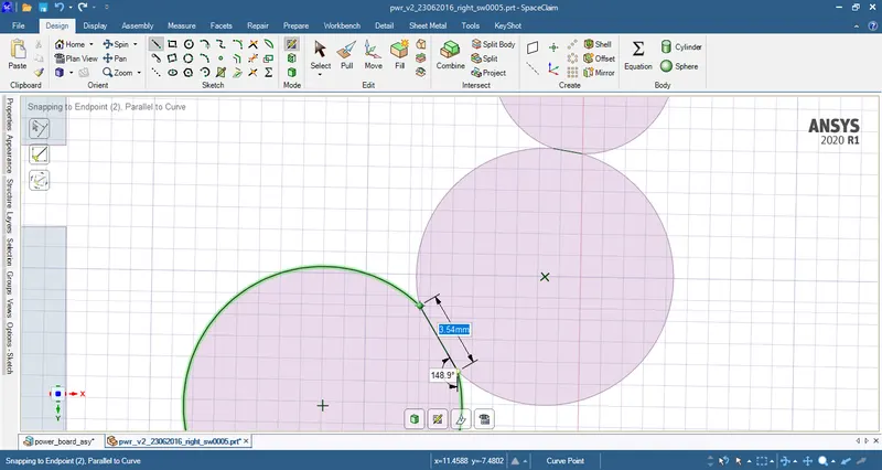
19. Use pull command to create 2 planes which can be used in the next step.
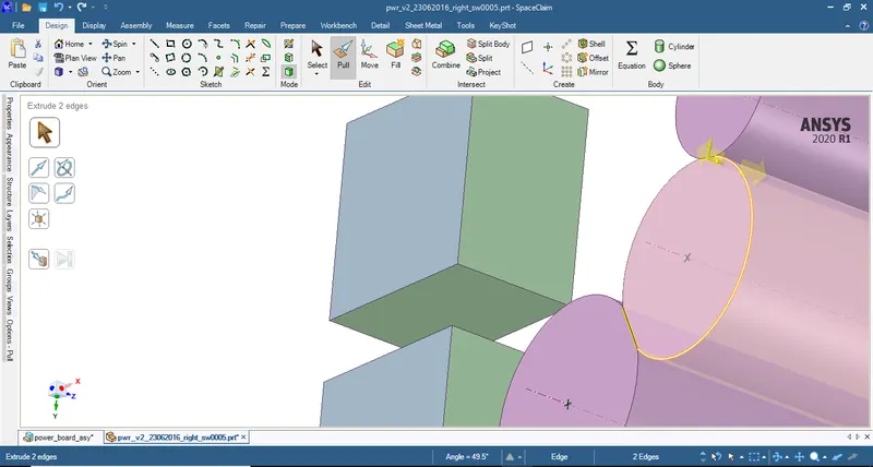
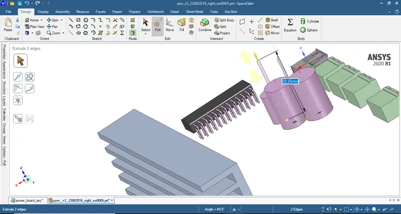
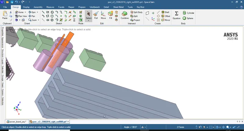
20. Use split body command to split the 3 cylinders using the planes created in the previous step.
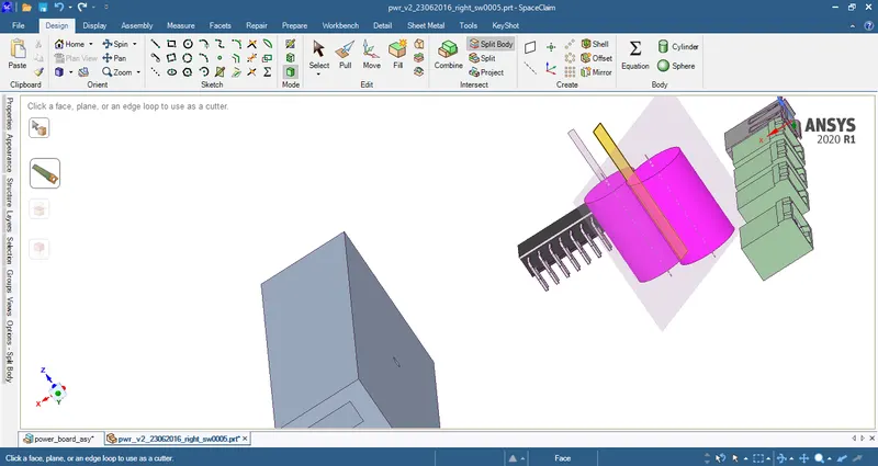
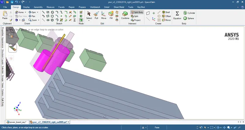
21. After spliting the cylinders delete the planes and use the ICEPAK simplify command and level 1 option to convert the 3 individual cylinders.
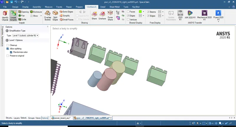
22. Delete the pins which donot participate in the heat transfer and the parts higlighted below are the parts to converted in the next step.
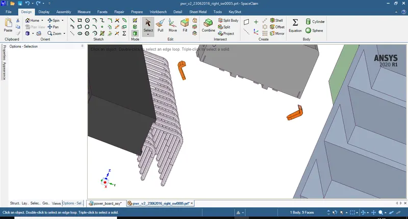
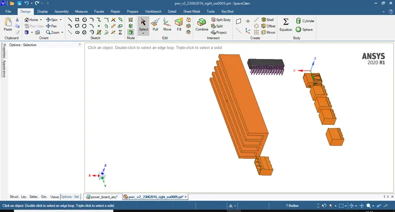
23. Select the ICEPAK simplify command and level 2 option and convert the above highlighted parts into ICEPAK objects.
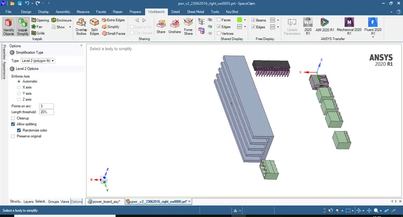
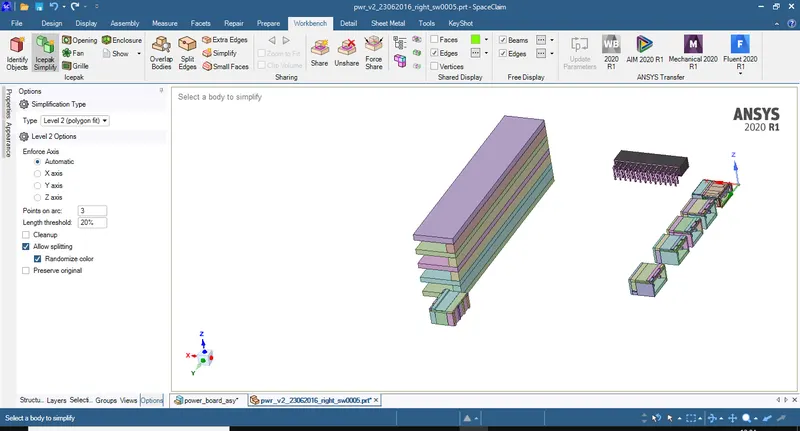
24. Split the below body by using the split body command and the below highlighted plane.
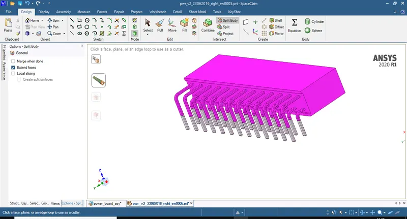
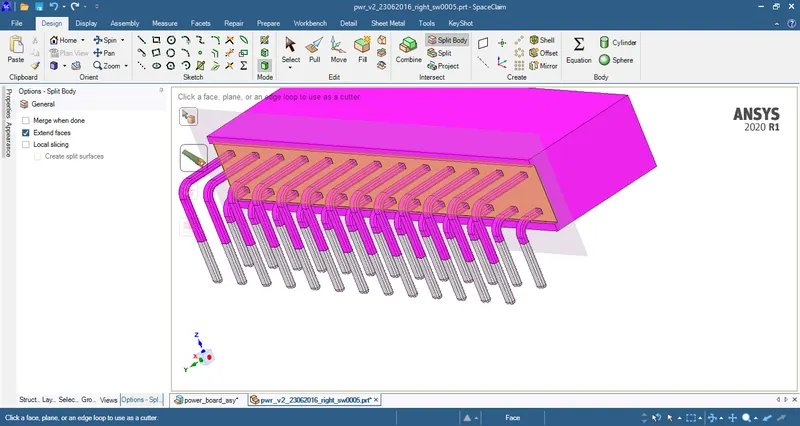
25. Use the ICEPAK simplify command and level 2 option convert the splitted bodies individually into ICEPAK objects.
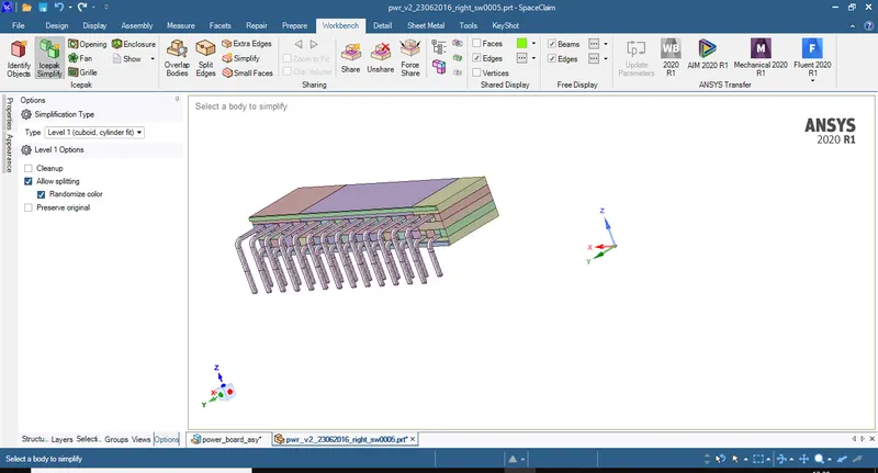
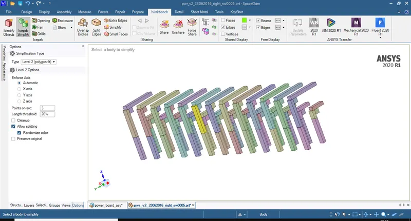
26. Close the PCB part tab and open the assembly tab. Select non-ICEPAK objects option in the show command and we will see only the enclosure which is to be converted.

27. Make the top part of enclosure invisible and using split body command split the bottom part of enclosure into different faces. Convert the below shown faces using level 1 option from ICEPAK simplify command.
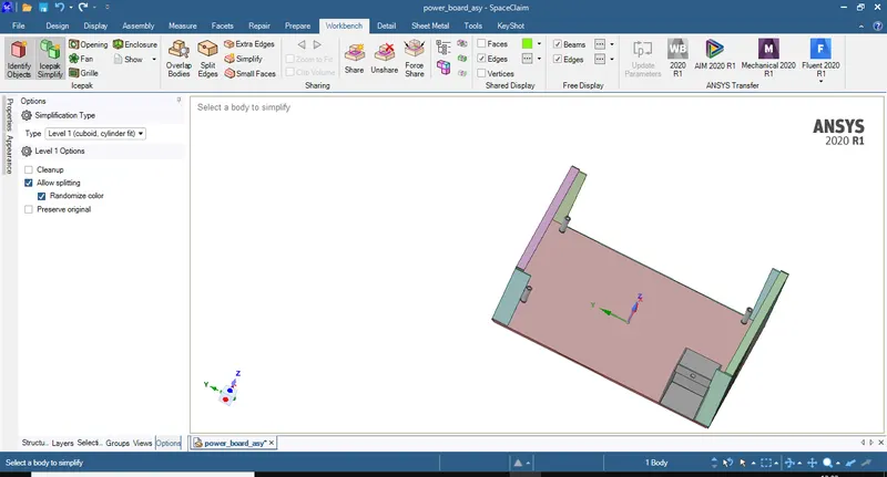
28. By using level 2 option from ICEPAK simplify command convert the below highlighted objects into ICEPAK objects.
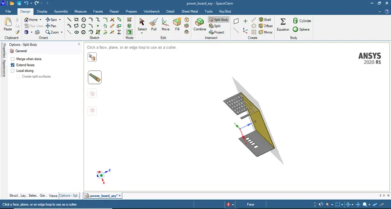
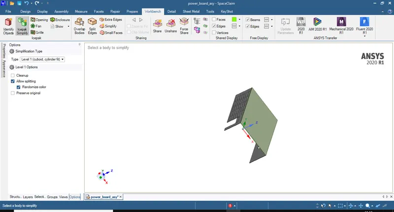
29. Make only the top part of enclosure visible and split it with the plane shown below and convert the face using level 1 option from ICEPAK simplify command to convert into ICEPAK object as shown below.
30. To convert the holes on the face into grille use Grille command and select the face on which the grille is to be generated.
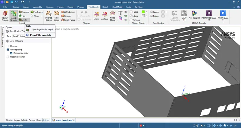
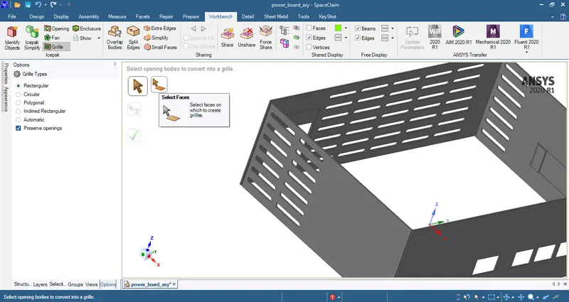
31. On the faces shown below grilles are created by selecting the faces directly.
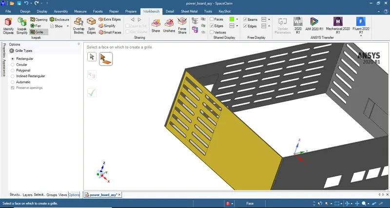
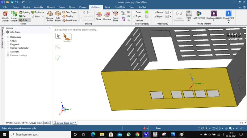
32. By using level 2 option in ICEPAK simplify convert only the faces on which grilles have been created in the previous step.
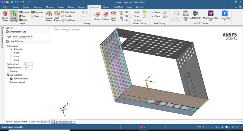
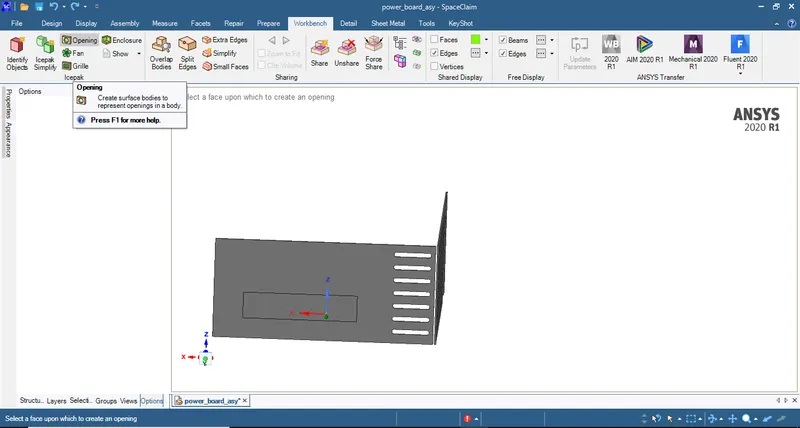
33. Select opening command to create openings on the faces shown below.
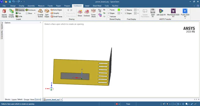
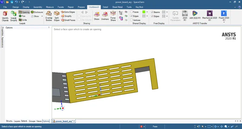
34. After openings are created select grille command to convert these openings into grille as shown below.
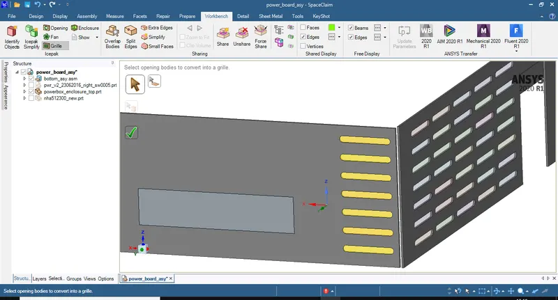
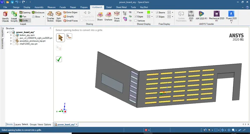
36. In the figure shown below delete the opening which is not required
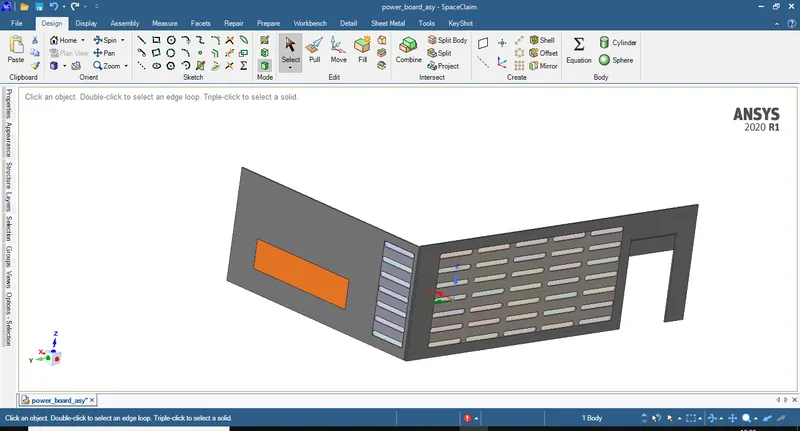
35. By using level 2 option from ICEPAK simplify convert the faces on which grilles have been created in the previous step.
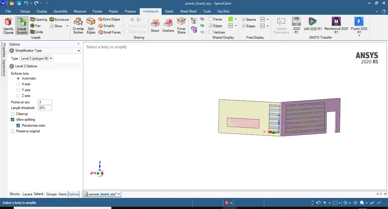
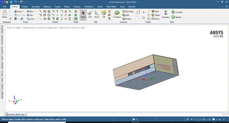
36. We can now see that the total assembly has been converted into ICEPAK objects from the figure shown below.
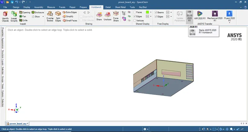
37. To open the workbench go to workbench tab and select WorkBench icon shown as WB and the workbench windown opens as in the figures below.
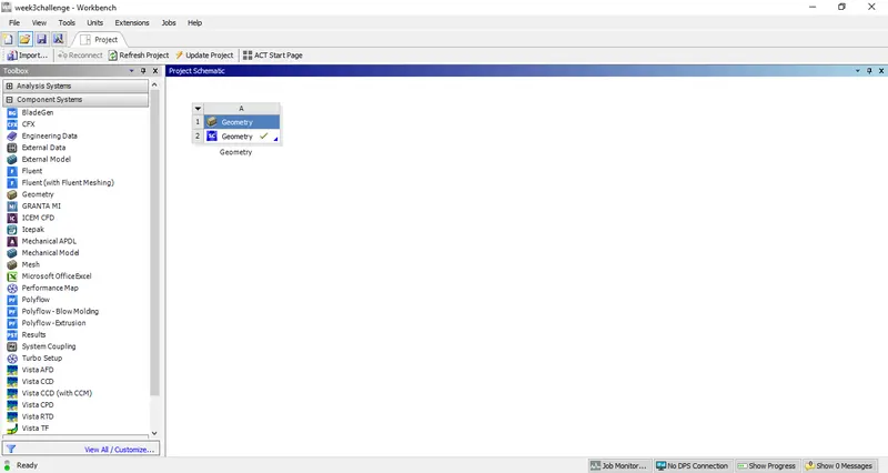
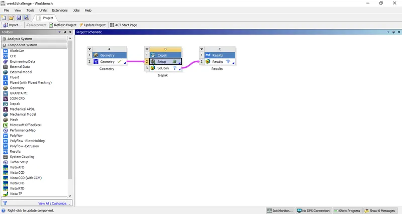
38. Drag ICEPAK and Results options on to the workbench and conncect them as shown in the figure below.
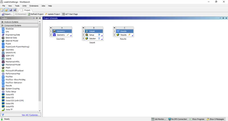
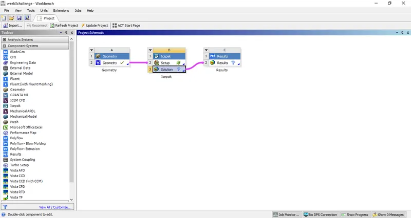
39. Open Setup option in the ICEPAK and we can see all the ICEPAK objects which were converted from CAD objects and grilles which were created before convertion into ICEPAK objects.
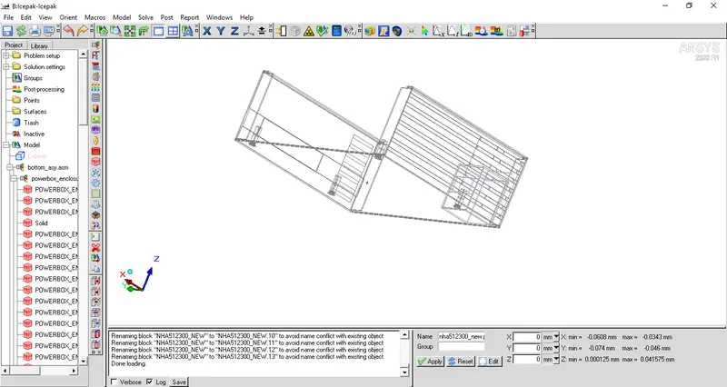
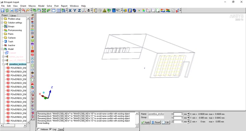
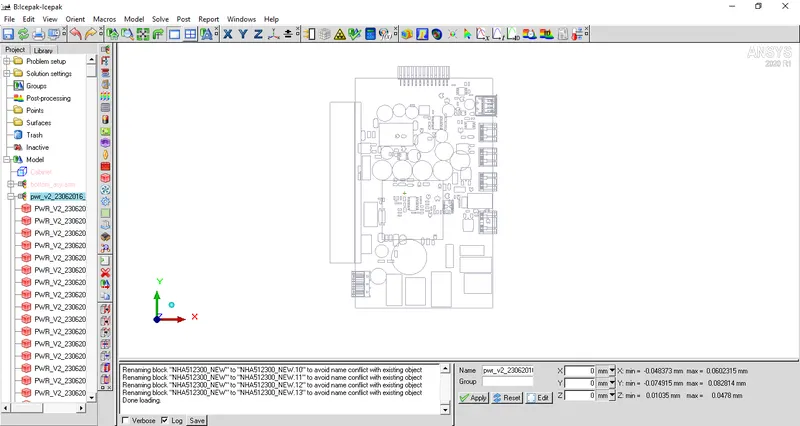
40. From the above figures we can see that every part that has been converted into ICEPAK object in the Space claim Direct moduler has been identified by the ICEPAK solver.