Week 3- Geometry cleanup and Mid-surfacing
Case 1:
To extract mid-surface for the tube model and provide a connection with sharing option at the tube joint locations
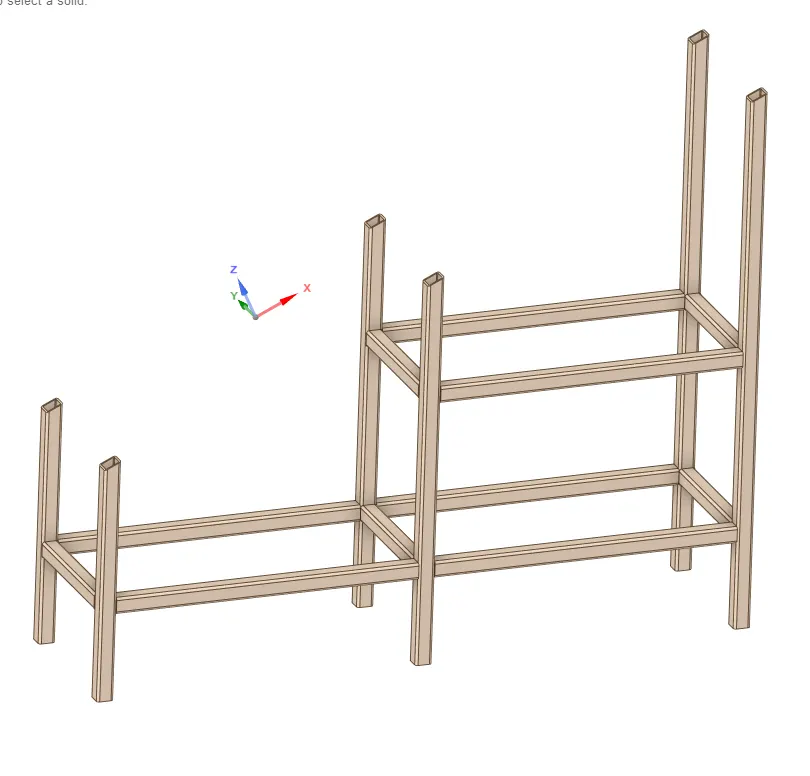
Step 1 : Import the Cad model in the Space claim
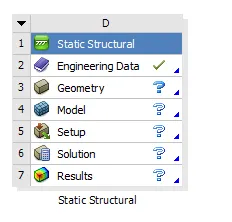
Import the model into the geometry where edit in space claim is to be selected.
step 2 : Creating a mid surface :
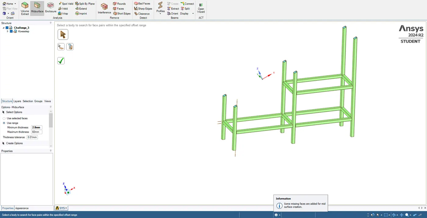
Select all the tubes and by giving tolerance of 0.01mm with minimum thickness of 2.8mm using range option .
one has to select first the outer surface and then the inner surface.
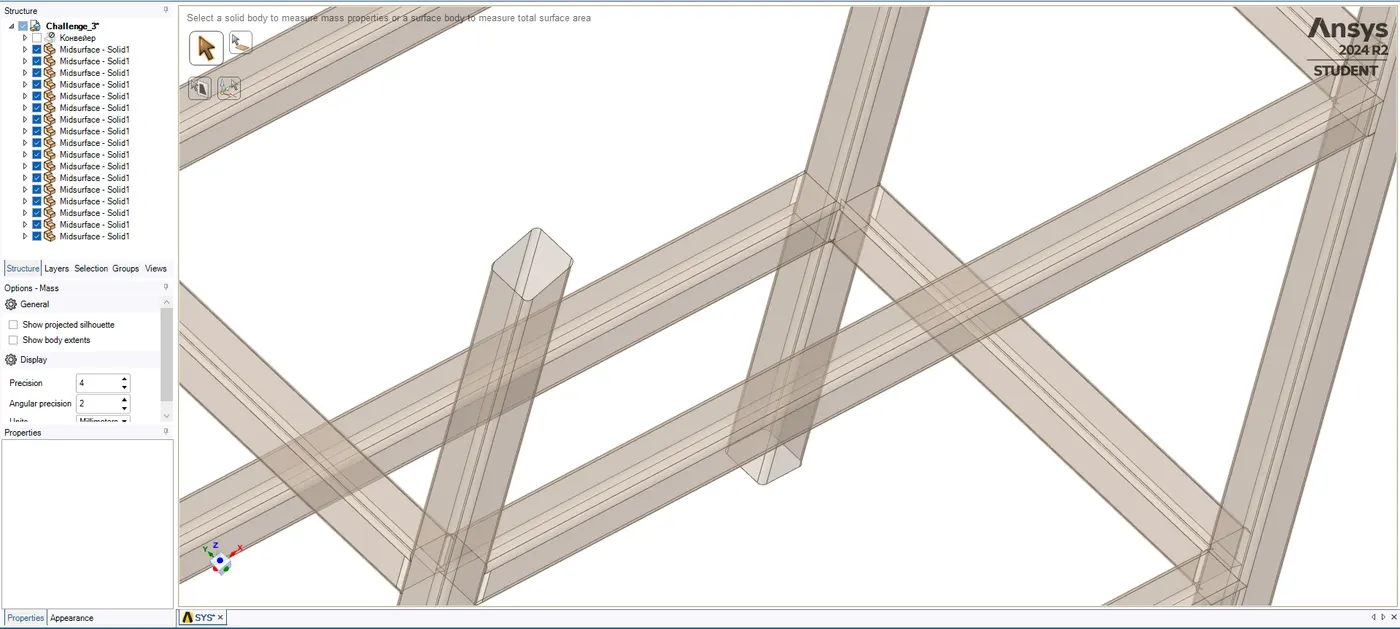
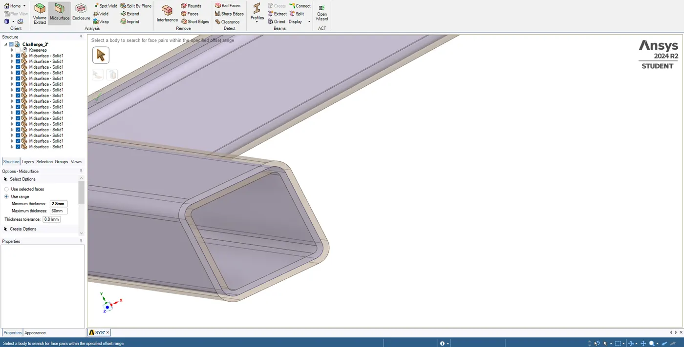
This is how the model looks once the mid surface is generated..
Step 3 : Extending the Faces or edges of the tubes.
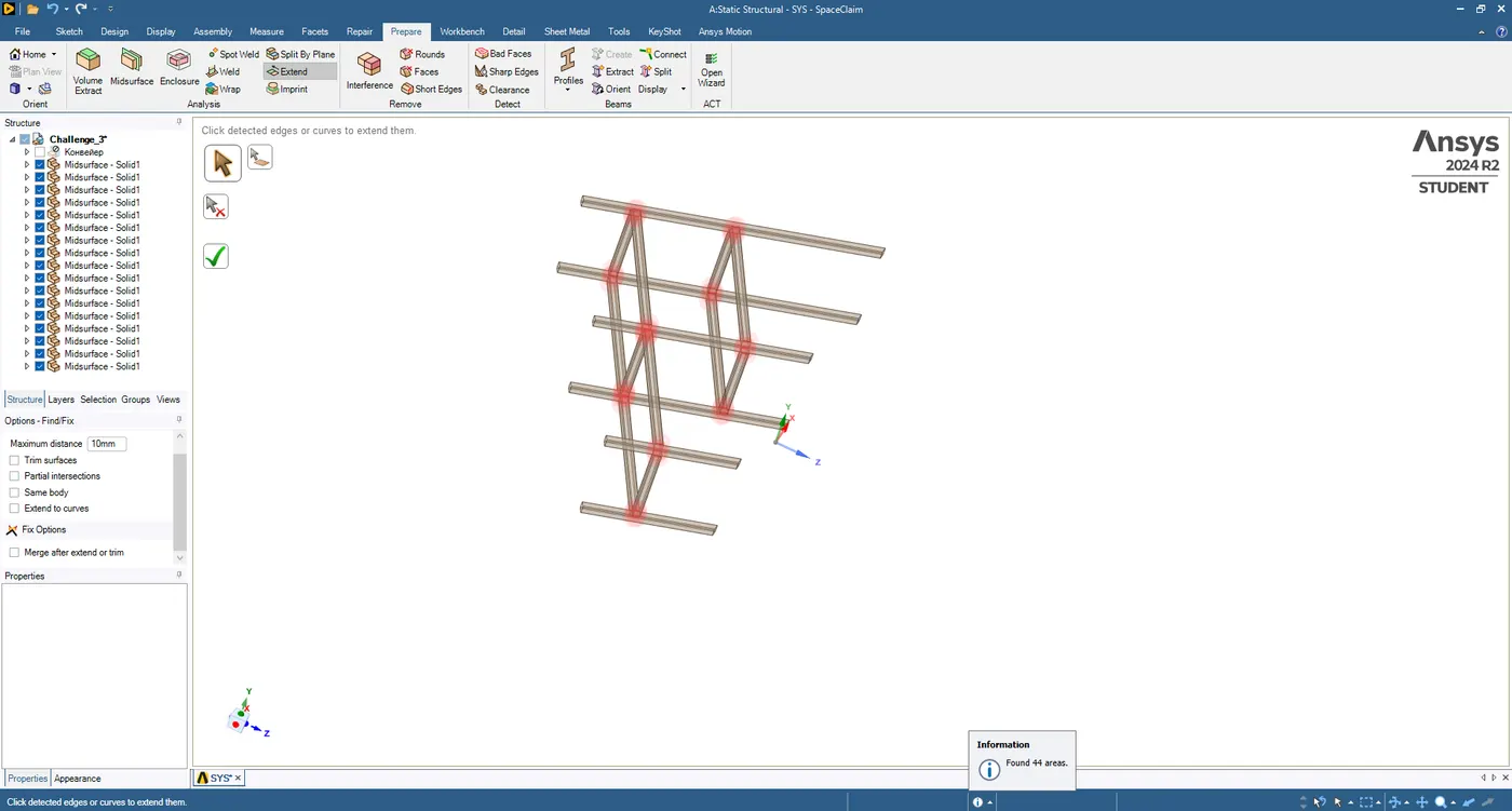
Here the red ones are indicating the extended areas.
Step 4 : Creating a share to connect the joints.
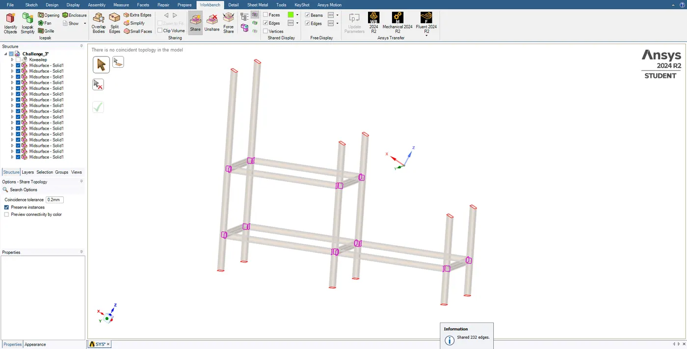
the purple markings are indicating that the joints have been shared with each other.
Case 2:
Create a model in Spaceclaim one on top of each other and create a shared topology between the top block and the bottom block.
Dimension of Top Block A: 20 x 20 x 5 mm
Dimension of Bottom Block B: 40 x 40 x 10 mm
Boundary Conditions: Provide Fixed support for the bottom face of Block B
Perform a modal analysis (free-free run) to verify connections and analyze the results.
Step 1 : Creation of Geometry
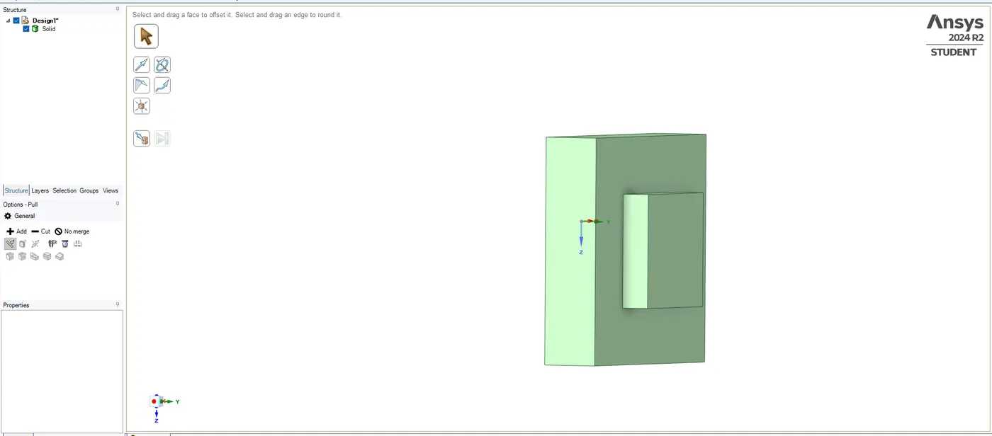
By using sketch tool first the bottom block is created of 40 x 40 x 10 mm and then the sketch is been extended using the pull command and then on the same block another sketch is made of 20 x 20 x 5 mm is also extended .
Step 2 : Split the Blocks
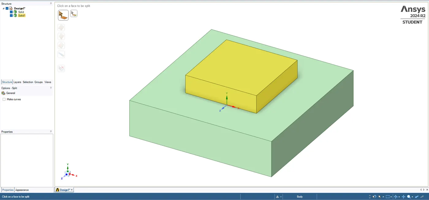
By using split body , both the bodies have been Separated from each other .
Step 3 : Creating a connection using share command.
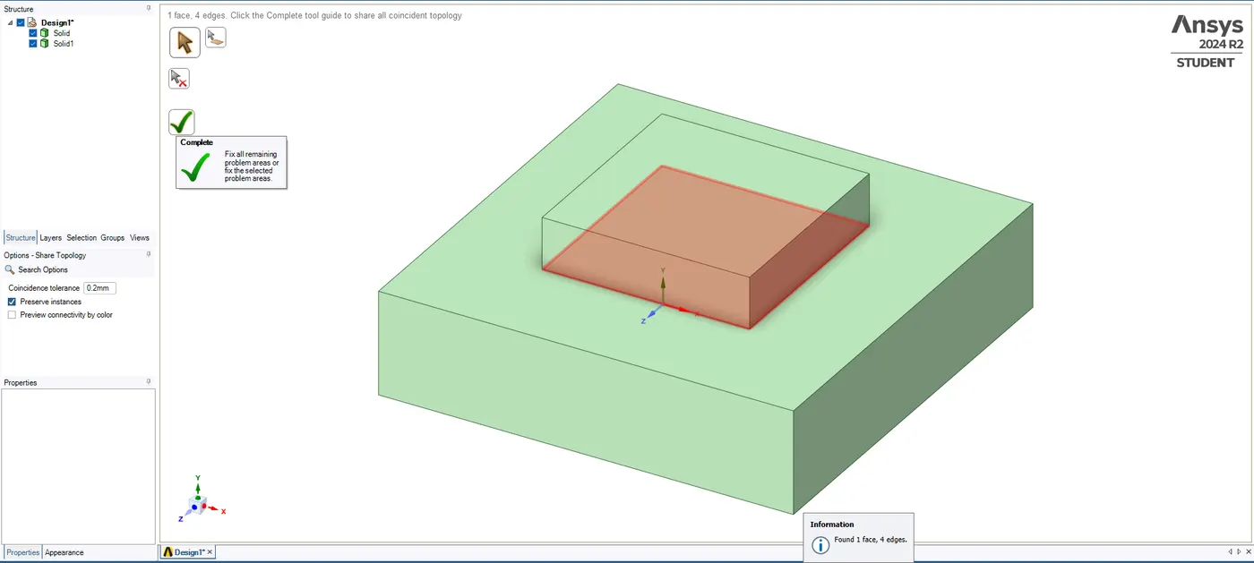
all the four edges have been found which needs to be shared.
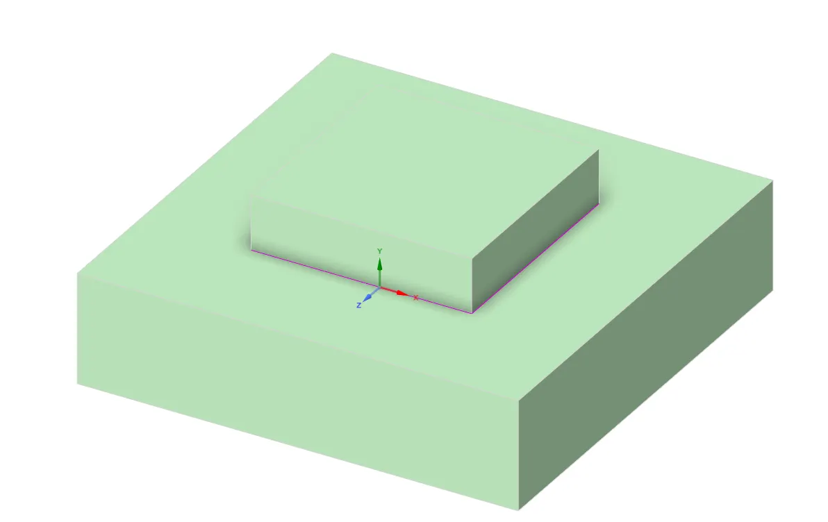
Step 4 : Material Properties in Engineering Data :
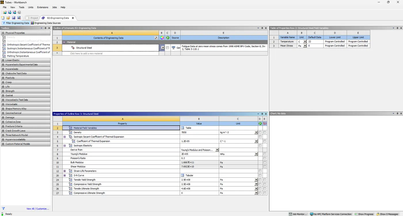
Step 5 : Creating Mesh on both the blocks
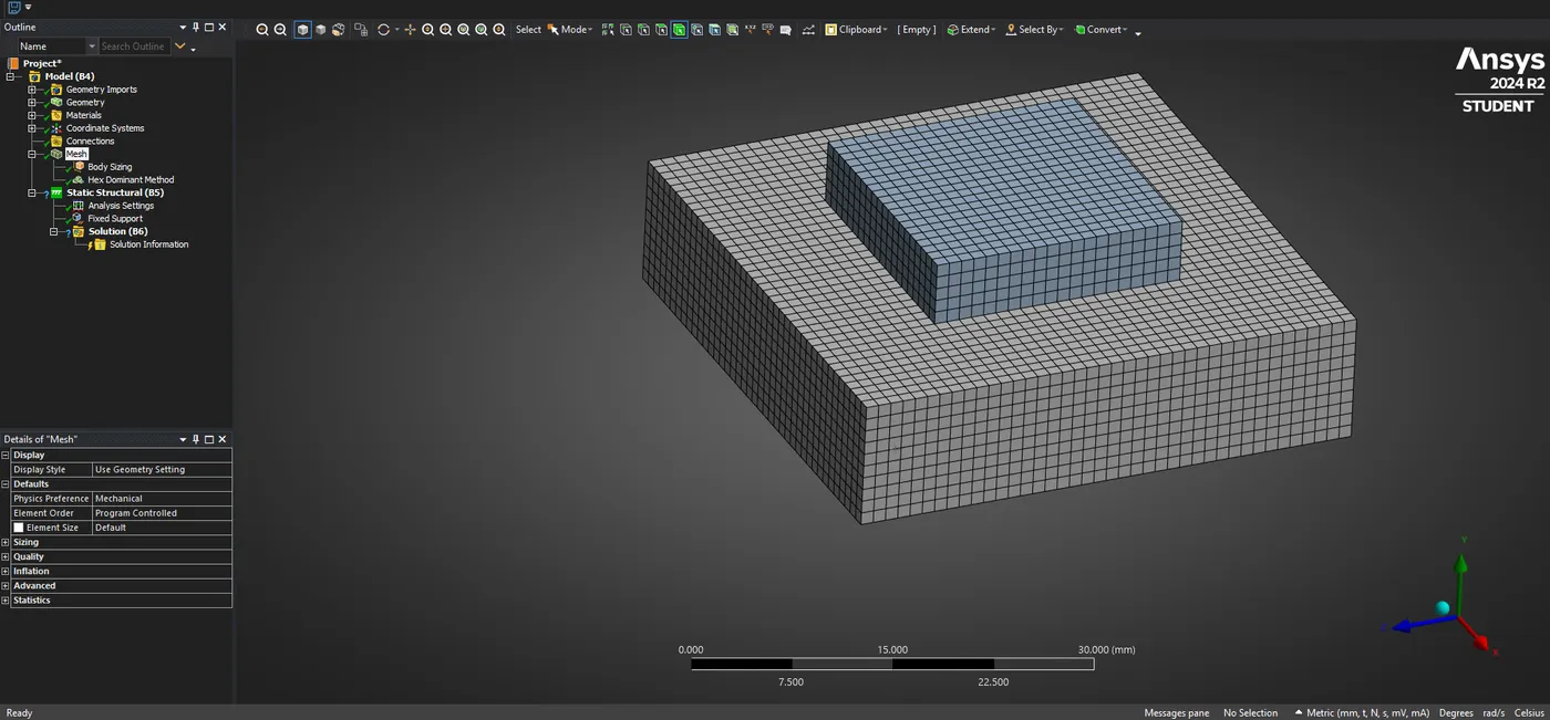
Hex Dominant method is been used with a body sizing of 1mm on both the bodies.
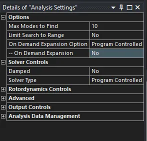
Step 6 : Modal Analysis Setting:
Modal Analysis is been inserted from the Analysis section and then the number of modes is changed upto 10 .
Step 7 : Creating the Boundary Condition :
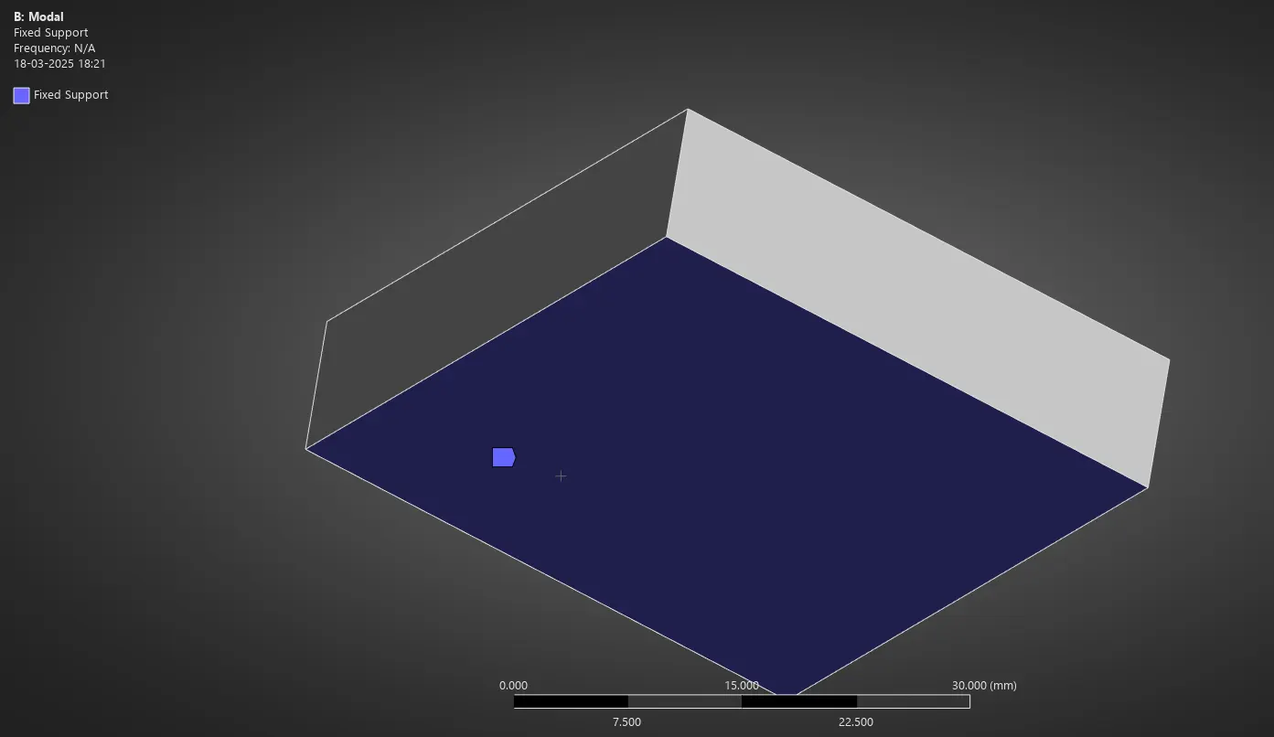
As per the Data , the fixed support is given on the bottom block and also no Gravity or force is been added.
Step 8 : Solving and Evaluating the results with Deformation.
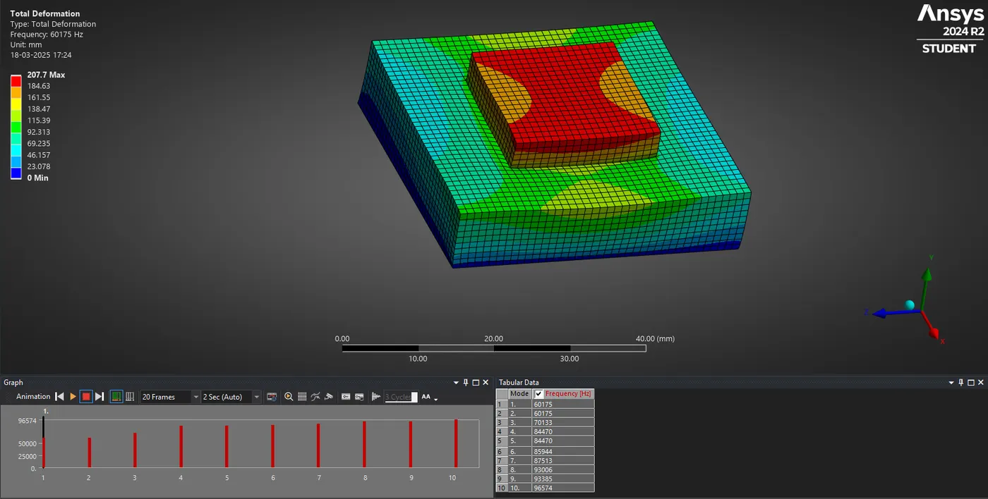
To Create the Modal results , select all the tabular data with the frequency and right click and select evaluate all results .
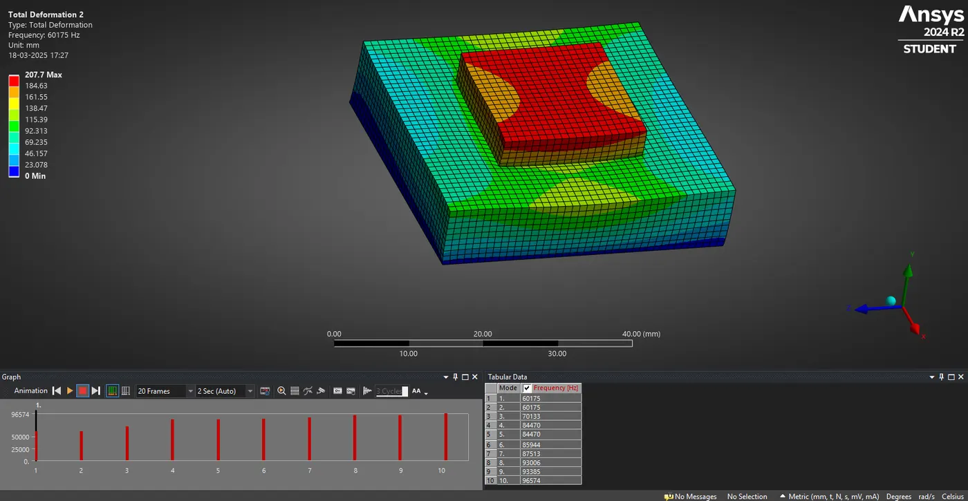
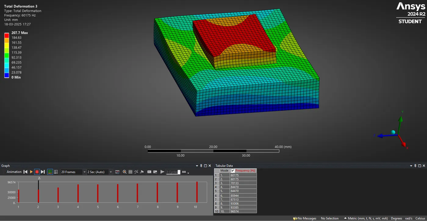
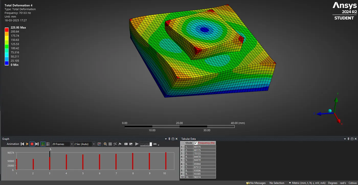
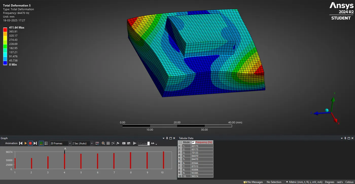
Step 9 : Mode results of all Deformation Shapes 10.
Mode 1 :
Mode 2 :
Mode 3 :
Mode 4 :
Mode 5 :
Mode 6 :
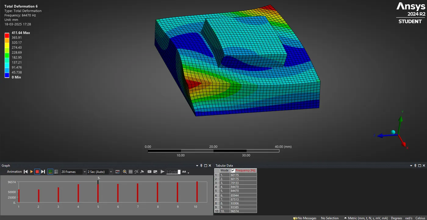
Mode 7 :
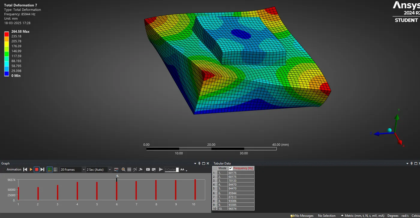
Mode 8 :
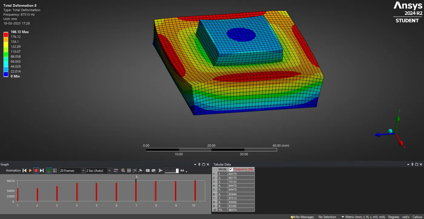
Mode 9 :
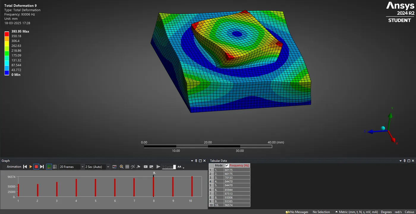
Mode 10 :
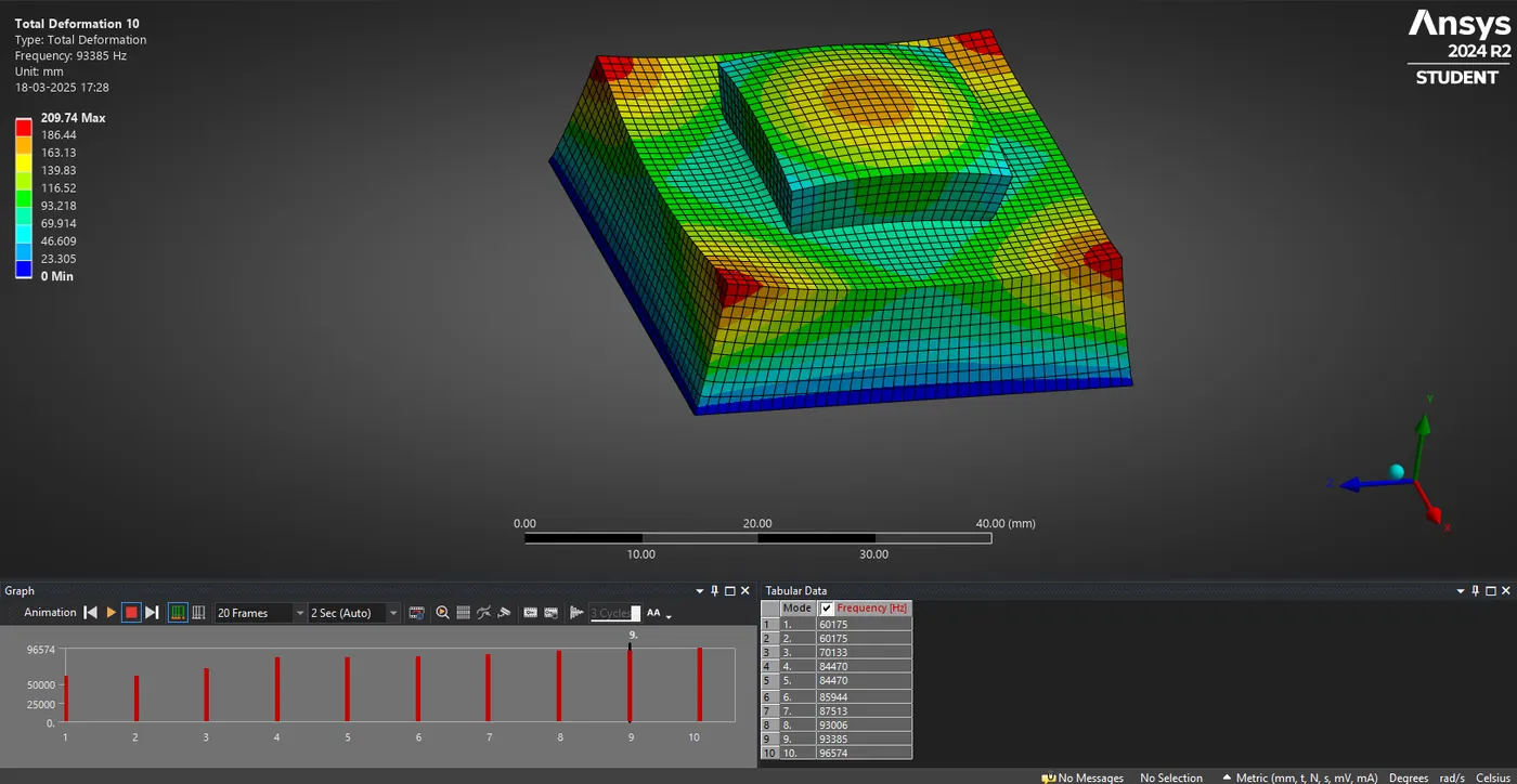
Analysis Results :
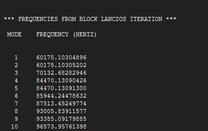
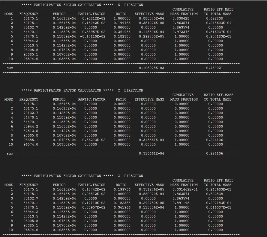
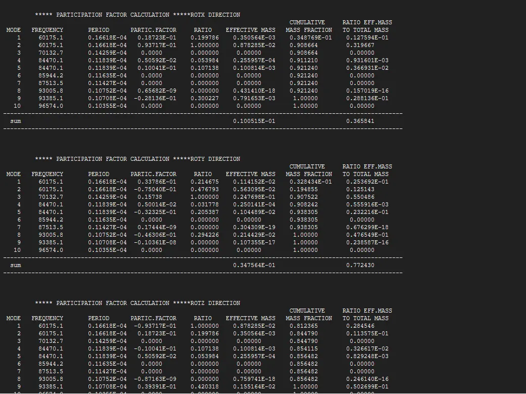
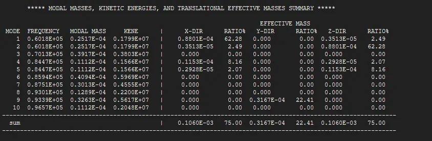
Modal Frequencies and Periods :
- The analysis identified 10 modes with frequencies ranging from 60175.1 Hz to 96574.0 Hz.
- The corresponding periods vary from 0.1661E-02 s to 0.1035E-04 s.
Conclusion :
- The structure's dynamic response is dominated by Modes 1, 2, and 4 in both the X and Z directions.
- The Y direction shows minimal participation, with only Mode 9 contributing significantly.
- The cumulative mass fractions in all directions indicate an adequate number of modes have been captured for reliable analysis.
Final Outcome :
- Understanding of mid-surface extraction, body splitting, and shared topology options in SpaceClaim.
- Ability to create and modify geometry in SpaceClaim.
- Knowledge of defining engineering data, meshing strategies, model setup, and post-processing techniques in ANSYS Workbench.