Week 3 - External flow simulation over an Ahmed body.
Ahmed body and its importance:
An important feature of a bluff body flow is that there is a very strong interaction between viscous and inviscid regions. Usually bluff bodies induce flow separation at positions where the velocity at the edge of the boundary layer is higher than the free stream velocity. Prediction of separation position from a continuous surface is difficult because it depends on characteristics of the upstream boundary layer and structure of the near wake region.
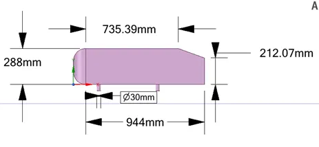
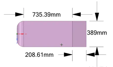
For a basic ground vehicle type of bluff body, a generic car body (a simplified vehicle model) is known as Ahmed body. The Ahmed body is an abstract representation of a bluff body type's ground vehicle geometry. Its design is basic enough to allow for precise flow simulation while retaining crucial functional aspects pertinent to car bodywork. The turbulent flow field around a straightforward car-like geometry is calculated using the model presented here. The airflow around the Ahmed body captures the essential flow features around an automobile and was first defined and characterized in the experimental work of S. R. Ahmed in 1984.
Three main features were seen in the wake:
- The recirculation region that is formed as the flow separates at the top of the vertical back surface of the model
- The recirculation region that is formed due to the separation at the base of the model.
- The vortices that form as the vorticity in the side boundary layers roll up over the slant edges.
The flow is essentially two-dimensional and has low drag. The drag increases significantly as the low-pressure cores act on the rear surfaces.
 |
 |
|
|
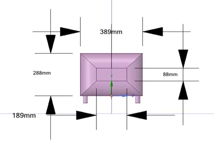 |
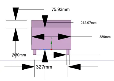
Schematic Diagram of an Ahmed Body
Q2. Explain the reason for the negative pressure in the wake region.
Negative pressure is due to the velocity difference applied at a certain Reynolds number and the rear angle of Ahmed body. The higher pressure air on the front surface accelerates as it travels over the curved nose surface, causing the pressure to drop. This lower pressure creates lift and the drag that then acts upon the surface area of the rear slant.
Q3. Explain the significance of the point of separation.
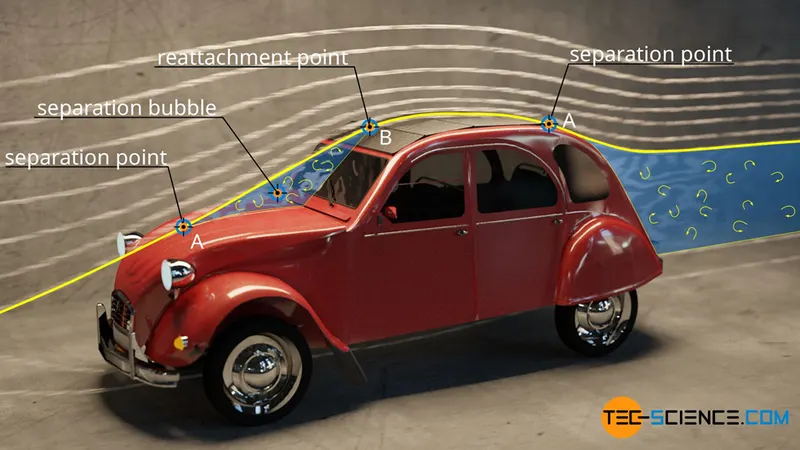
When a fluid flows around a body, forces act between the fluid and the surface due to the viscosity. These intermolecular forces are the cause for the drag, among other things. This is because the surface of the solid body also tries to bind the fluid to itself.
As long as the contour of a body has smooth transitions and the internal cohesion of the fluid (viscosity) is large enough to resist the inertial forces, a flow can follow the contour. A typical hydrodynamic boundary layer develops around the body, the thickness of which is largely influenced by the viscosity.
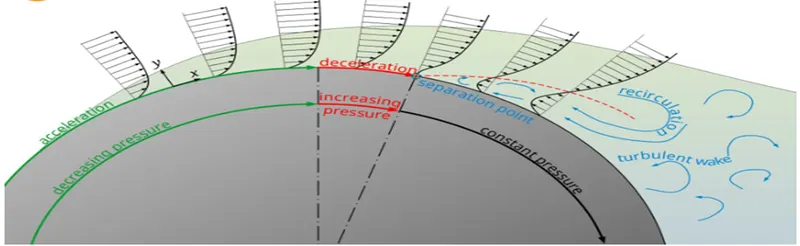
The effective cross-section of the flow increases, as the cylinder cross-section decreases (the flow has more space, so to speak). The flow slows down and the static pressure rises again in the x-direction to finally reach the level of the atmosphere (∂p/∂x>0). This pressure gradient acting against the actual direction of flow is called adverse pressure gradient.
Pre Processing Approach:
Geometry:
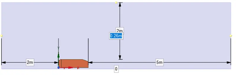
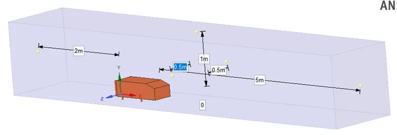
From the above given dimensions geometry was modelled in any designing software’s, and the model is brought up in Ansys Fluent Workbench space claim, and can be repaired for the given requirement. In order to see the flow properties over the Ahmed body some design should be added like wind tunnel. This can be done by using Enclosure option. Enclosure is the option which will build the shape outside the Ahmed body.
The box distance from the Ahmed body for different directions is;
Front-2mt in X axis
Back-5mt in X axis
Top-1mt in Y axis
Bottom-0mt in Y axis
Sides- 0.5mt in Z axis
 |
 |
Mesh:
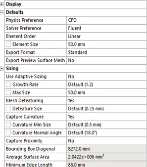
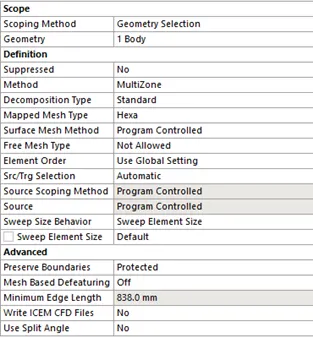
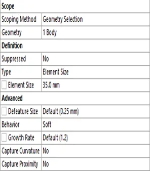
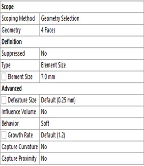
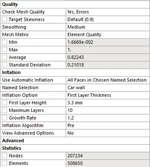
In meshing initially default mesh has been generated. By generating this we can find how to improve the geometry by providing different mesh parameters. These are the locations where the mesh has been overlapping, in the holes region the mesh is generated as polygon shape. Here for my analysis I use 2 different mesh sizes like 50 mm and 100 mm for outer symmetry walls, and for inner walls and Ahmed body I use 25 mm and 50 mm, and for holes I use 5 mm for better quality of analysis.
|
|
|
|
|
Fig (C) |
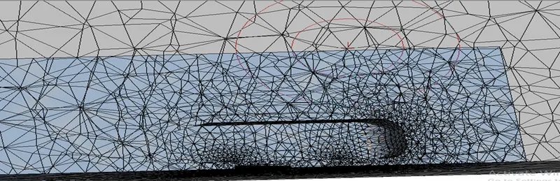 Fig (A)
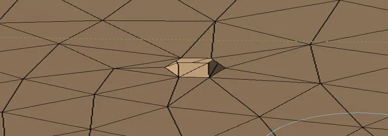 Fig (B)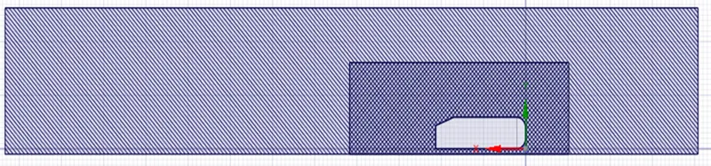
Interference:
In order to have the refinement solution where the results are accurate near the Ahmed body a small body is generated. Near this region in fig (C) the mesh overlapped can be solved by using interference tool in geometry space claim. This is done because the mesh should share between these components. In order to do this we should use the share options so that the mesh should generate between these models.
Inflation:
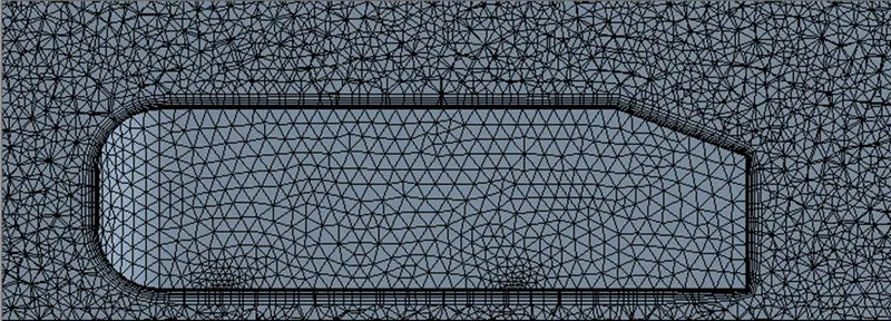
Inflation is use when analysis of boundary condition is done accurately by create finer mesh near to wall or near to boundary. Inflation is also useful for CFD boundary layer resolution, electromagnetic air gap resolution or resolving high stress concentrations. Here we are using 7 layers of thickness of total thickness calculated by growth ratio. The growth ratio is 1.2 hence the thickness can be calculated by 7*(1,2)^7.
Solving:
When a Mach number is above 0.3 in order to see the flow properties density based solver is used. If the Mach number is less than 0.3 pressures based solver is used. Since we need to see the flow properties of a ahmed body within a wind tunnel like structure the velocity is by 2 cases 25 and 50 m/s respectively. The turbulence model here we took here is K-Ɛ model and energy equation should be taken into consideration. In order to get the required drag coefficient the wall distance is taken from the appropriate Y+ and is taken from the given link http://www.cfdyna.com/CFDHT/Y_Plus.html
|
Boundary conditions |
Factors |
|
Solver |
Density |
|
Turbulence |
K-Ɛ model |
|
Energy |
On |
|
Inlet velocity |
25 m/s |
|
Outlet |
1 atm |
|
Solution |
Hybrid |
|
Iteration |
100 |
|
Y+ value |
100 |
|
Wall distance |
3.63 mm |
 |
 |
 |
 |
 |
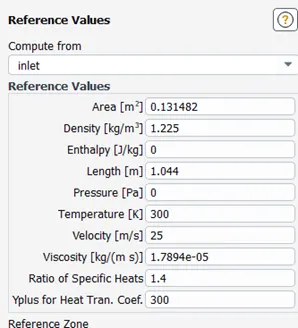 |
By giving Hybrid initialization we should set some post-processing factors like velocity contour, Pressure contour, solution Animation, Lift and drag force etc. after giving 100 iterations following results are obtained.
Post-Processing Results:
|
Mesh Quality |
|
|
|
|
|
|
 Default Mesh
 100 mm Mesh
 50mm Mesh
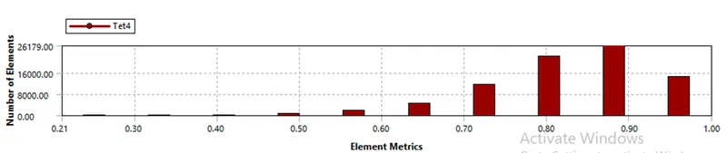
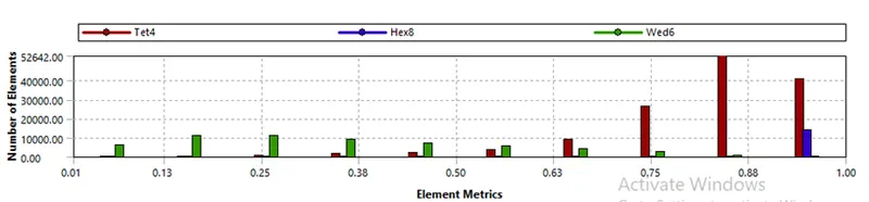
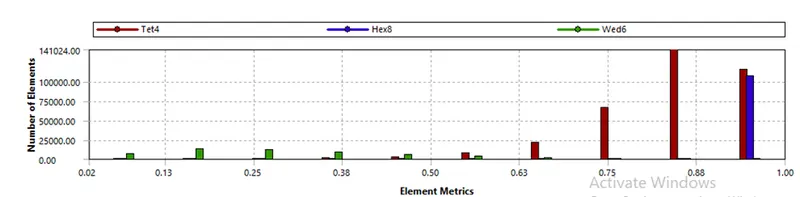
 The mesh element quality is a dimensionless quantity between 0 and 1, where 1 represents a perfectly regular element, in the chosen quality measure, and 0 represents a degenerated element. Element quality > 0.3 is termed as good.
|
Residuals |
|
Default Mesh
|
|
100 mm Mesh
|
|
50mm Mesh
|
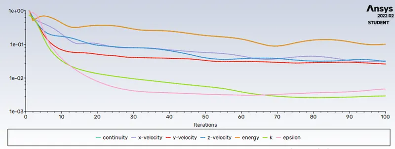
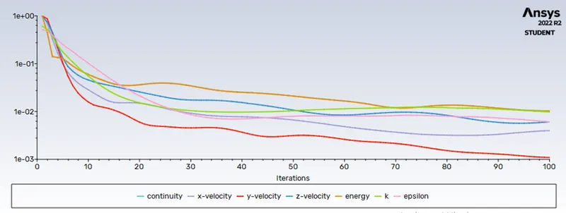
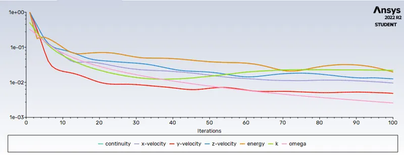
In CFD, residuals are employed to monitor the behaviour of the numerical process, they implicate whether the solution shows a trend of convergence or divergence. In a CFD analysis, the residual measures the local imbalance of a conserved variable in each control volume.
|
Drag coefficient |
||
|
Default Mesh
|
||
|
100 mm Mesh
|
||
|
50mm Mesh
|
||
|
Default Mesh |
100 mm Mesh |
50mm Mesh |
|
Drag- 0.2525 |
Drag- 0.4996 |
Drag- 0.3231 |
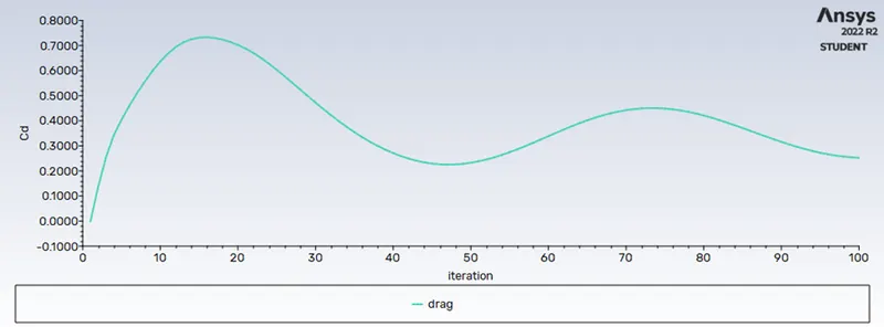
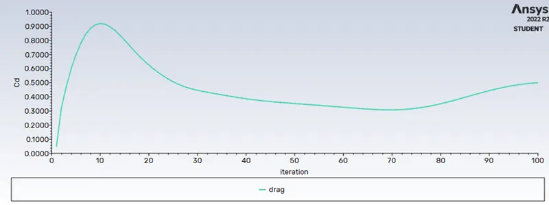
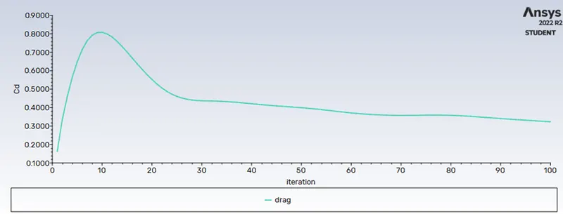
From the above graph we can see the flow has been diverged for default mesh and 100mm mesh but it was converged for low mesh size.
|
Lift Coefficient |
|
Default Mesh
|
|
100 mm Mesh
|
|
50mm Mesh
|
|
Velocity Contour |
|
|
Default Mesh
|
|
|
100 mm Mesh
|
|
|
50mm Mesh
|
|

|
Pressure Contour |
|
|
Default Mesh
|
|
|
100 mm Mesh
|
|
|
50mm Mesh
|
|

|
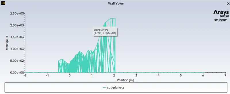
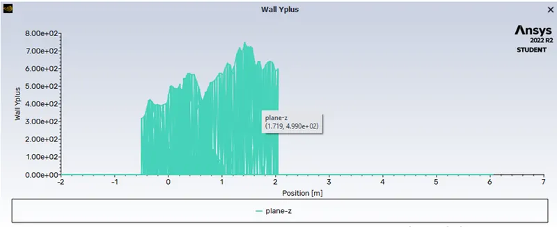
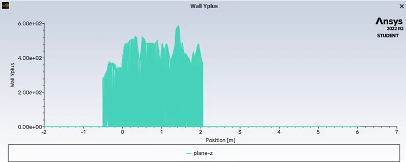
XY plot(Wall Y plus v/s Position) |
|
Default Mesh
|
|
100 mm Mesh
|
|
50mm Mesh
|
|
Flow near ahmed body1 |
|
Default Mesh
|
|
100 mm Mesh
|
|
50mm Mesh
|
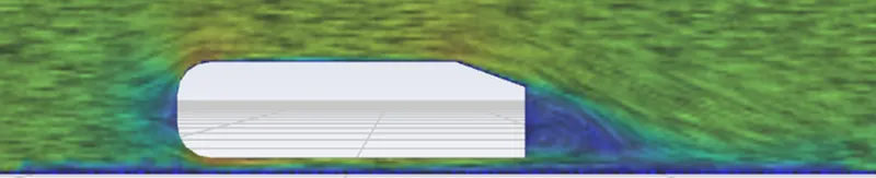
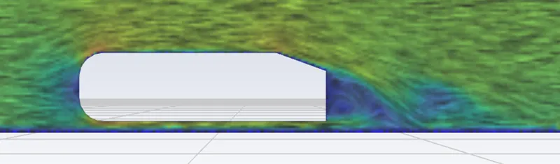
|
Flow near ahmed body2 |
|
Default Mesh
|
|
100 mm Mesh
|
|
50mm Mesh
|
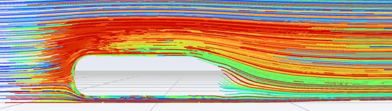
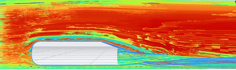
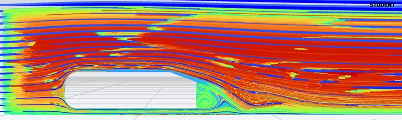
|
Velocity vectors near ahmed body3 |
|
Default Mesh
|
|
100 mm Mesh
|
|
50mm Mesh
|
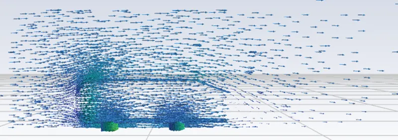
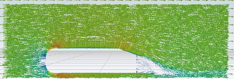
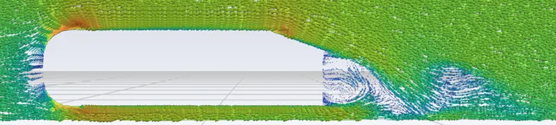
|
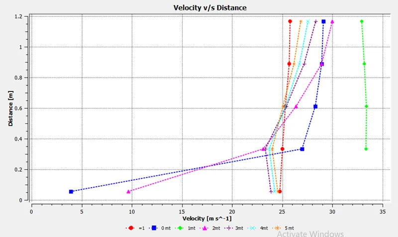
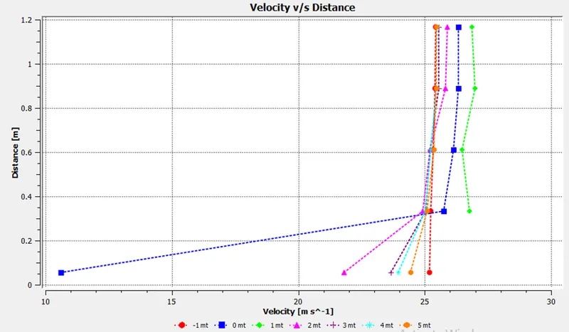
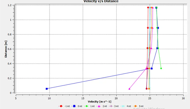
Velocity along the pipe length |
|
Default Mesh
|
|
100 mm Mesh
|
|
50mm Mesh
|
|
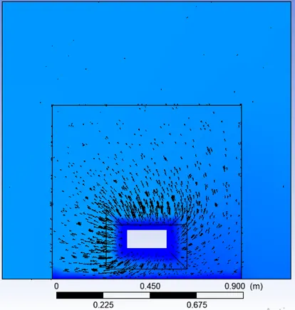
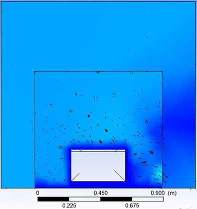
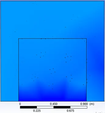
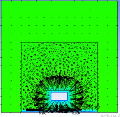
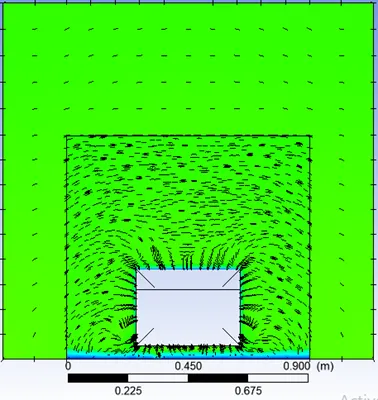
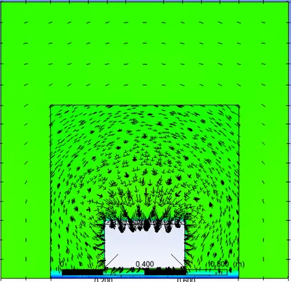
Velocity vectors along the 5 locations |
|
|
Default Mesh
|
|
|
|
|
|
|
|
 0 mt
0 mt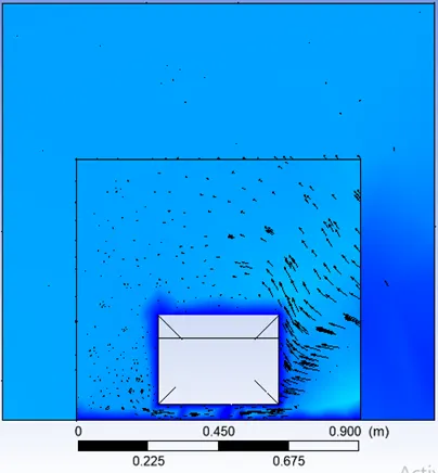 0.5 mt
 1 mt
1 mt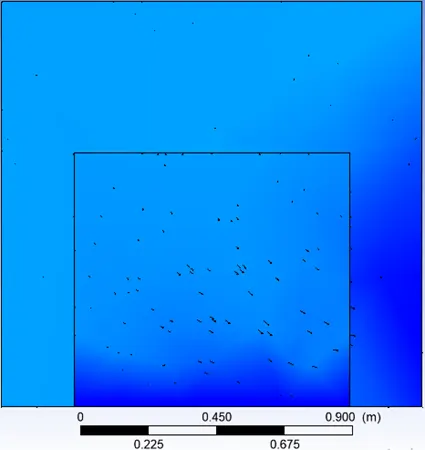 1.5 mt
 2 mt
2 mt
|
Velocity vectors along the 5 locations |
|
|
100 mm mesh
0 mt |
|
|
|
|
|
|
|
 0.5 mt
 1 mt
1 mt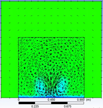 1.5 mt
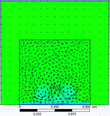 2 mt
2 mt
|
Velocity vectors along the 5 locations |
|
|
50 mm mesh
|
|
|
|
|
|
|
|
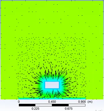 0 mt
0 mt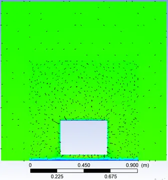 0.5 mt
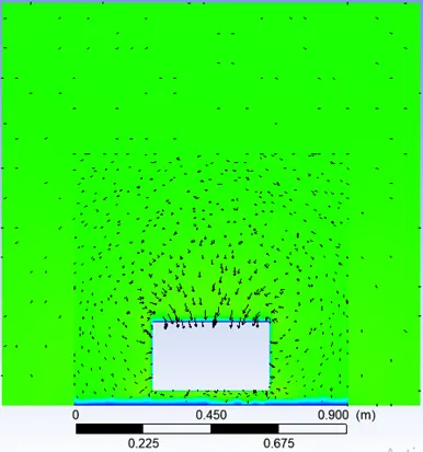 1 mt
1 mt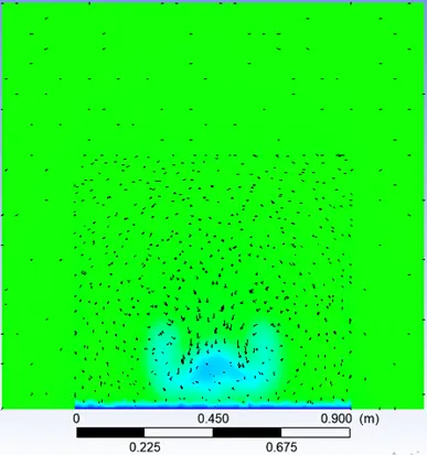 1.5 mt
 2 mt
2 mt
|
Mesh Size |
||
|
Default Mesh |
100 mm Mesh |
50mm Mesh |
|
Nodes- 16,194 |
Nodes- 70,776 |
Nodes- 2,07,234 |
|
Elements- 80,868 |
Elements- 2,03,968 |
Elements- 5,08,650 |
|
Drag, Lift, &Velocity |
||
|
Default Mesh |
100 mm Mesh |
50mm Mesh |
|
Drag- 0.2525 |
Drag- 0.4996 |
Drag- 0.3231 |
|
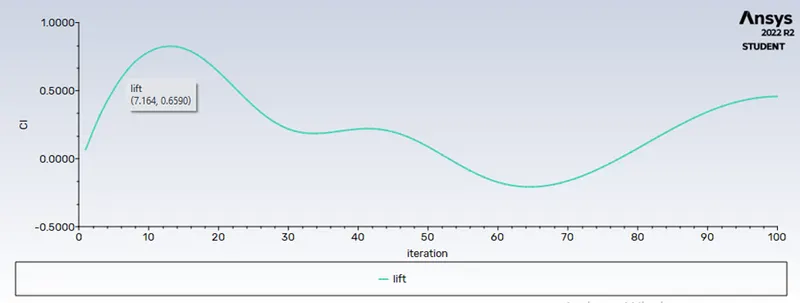
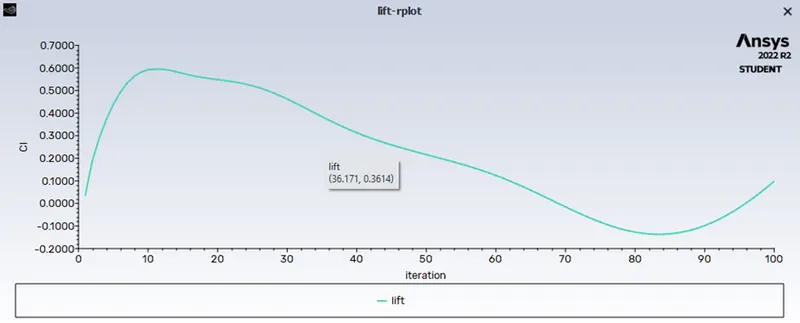
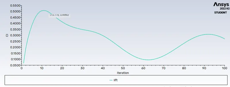
Lift- 0.4570 |
Lift- 0.298 |
Lift- 0.2705 |
|
Velocity- 22.78 m/s |
Velocity- 21.87 m/s |
Velocity- 20.32 m/s |
Results & Conclusion
- From the above tables, we can conclude that as the mesh size decreases the number of elements and nodes will increases drastically, which will help to study the flow behavior.
- We can see that for the default mesh, the drag coefficient is 0.25 and the lift coefficient is 0.45 and the velocity is 22.78 m/s. when we go for different mesh sizes like 100 and 50 mm mesh the drag coefficient increases in 100 mm mesh and decreases for the 50mm mesh size which is the required one.
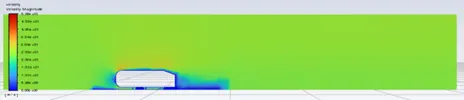
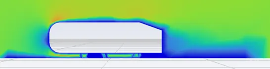
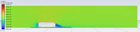
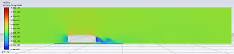
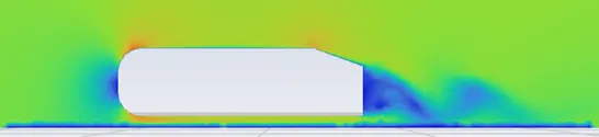
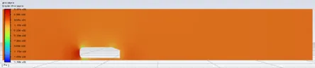
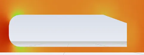
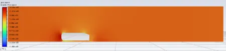
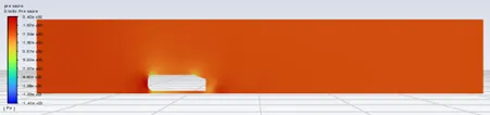
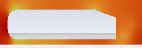
- In the velocity contour we can see that for the default mesh the flow after the Ahmed body doesn’t give the proper result, but when we see the 50mm mesh we can see that the flow has given the good results like the vortices & wake region are visible in this velocity and pressure contour.
- We can see that in XY plot the wall Y plus and position gives an idea about where the exact flow has giving the proper analysis results this is locate between -1mt to 2 mt length of the channel position.
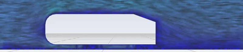
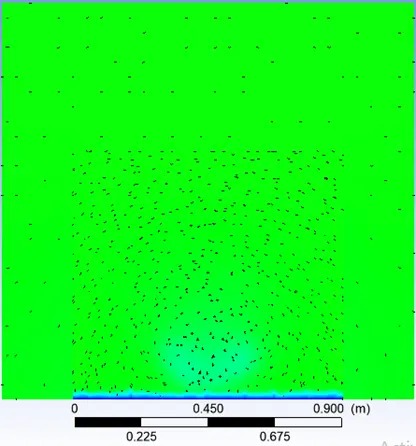
- The flow convergence can be seen through the path line plot, lic plot and vectors plot. In the default mesh the flow is straight but for the mesh size of 100 and 50 the flow in front of the ahmed body shows the flow separation, wake region, vortices, reverse flow.
- The velocity v/s distance chart shows the different line position along the channel and clearly explains the velocity when and where is exactly starts.
- At last in the post processing I took different planes along the length of the channel to see the velocity vectors how it converges and where exactly it converges.
- The values of drag coefficient agree with the referred publications.
Reference
- CFD Aerodynamic Analysis of Ahmed Body, Rehan Salahuddin Khan1 , Sudhakar Umale2 1 M.E. Student, Mechanical Engineering 2Associate Professor in Mechanical Engineering Sardar Patel College of Engineering Mumbai-400058, Maharashtra, India.
- Aerodynamic drag reduction and flow control of Ahmed body with flaps Jie Tian, Yingchao Zhang, Hui Zhu and Hongwei Xiao.
- Experiments and numerical simulations on the aerodynamics of the Ahmed body W. Meile1 , G. Brenn1 , A. Reppenhagen2 , B. Lechner2 , A. Fuchs2C 1 Institute of Fluid Mechanics and Heat Transfer (ISW), Graz University of Technology, Inffeldgasse 25/F, 8010 Graz, AUSTRIA 2 The Virtual Vehicle Competence Center (ViF), Inffeldgasse 21a, 8010 Graz, AUSTRIA.
- Flow and Turbulence Structures in the Wake of a Simplified Car Model (Ahmed Model) H. Lienhart, C. Stoots, S. Becker Lehrstuhl für Strömungsmechanik (LSTM) Universität Erlangen-Nürnberg Cauerstr. 4, 91058 Erlangen, Germany