Week 3 - External flow simulation over an Ahmed body.
AIM: To simulate the external flow over Ahmed body
Introduction:
Ahmed Body:
The Ahmed body is a generic car body (a simplified vehicle model). The airflow around the Ahmed body captures the essential flow features around an automobile and was first defined and characterized in the experimental work of Ahmed. Although it has a very simple shape, Ahmed body allows us to capture characteristic features that are relevant to bodies in the automobile industry.
This helps in studying the drag force on vehicles. That helps in studying the optimal maintenance the fuel economy by reducing the drag force
Wake Zone:
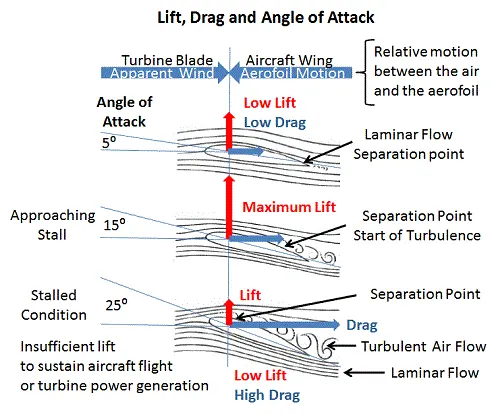
When fluid flow over any surface, especially on curved surfaces, the flow gets separated because of the momentum of fluid in the tangential direction is high compared to the surface plane. This separation occurs due to the negative pressure gradient.
So, after the separation, the turbulent region produced behind the body is called the wake region. Where the pressure gradient is negative, because of no flow of fluid in that region and low density of fluid particles
Separation point
The separation point is the point where the air stops "sticking" to an object that is moving through the air. When an object moves through the air, the air molecules push back on it and resist the object's movement - this resistance is called pressure drag. As the air flows around the object, it "sticks" to the thing, forming what is known as the boundary layer. This "attached flow" is flowing very smoothly. The point on the body where the boundary layer lifts off the surface is called the separation point. When the airflow separates from the surface, the pressure drag usually increases.
Solving and modeling approach:
- Geometric clean-up is done by using the Split body command to make the model into two halves. As the model is a symmetric body, it would be easier to simulate a low no of elements (smaller models).
- With the range of y+ calculations, we go with a k-epsilon model
- We see the effect of the mesh by designing 3 different mesh models coarser, fine, and finer models, and check the drag coefficient by simulating at the inlet velocity of 25m/s.
Pre-processing
- upload the model in the space claim, as it is a symmetric model we divide the model into two halves by using split body command
Split body command (create a plane before the split for precise separation)
àselect saw and draw plane before this
- we enclose the body (as it is an external flow analysis), by using the enclosure command
Enclosure command to draw enclosure à box, cylindrical type, etc
With outer box dimensions
Front= 2x;
End= 5x
One- side 0.5x;
another side = 0 (central axis)
top 1x;
bottom=0
Where x=1048.77mm (length of the body measured)
- By a similar procedure create another enclosure with half of the dimensions of outer enclosure
- now intersect the double created bodies using Interface command àoverlap surfaces
- Suppress model for physics
- Share topology to the inner enclosure
Meshing
- Initially name the faces
Inlet naming
Outlet naming
Other four faces symmetry
Materialsà grey colored (hide faces after) à box selection and name car wall
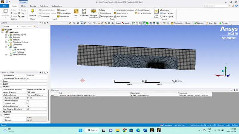
- do individual meshing for each body by Insert meshing
- for car walls: Geometry selection to name selection à element size 20
Or insert the automated method multizone mesh (tetra CFD) cell count reduces
- For inflation layer: Inflation à first layer thickness 0.4mm (measured from y+ calculator with y+ value of 30) àmax layers 15
- for different meshing of enclosed bodies: Insert meshing and select the bodies (only outer body) in type select multistage meshing
- for precise circularity of mesh: At cylindrical profiles à to improve circularity use insert àface sizingà5 mm element size. (optional for the current study, this might increase the cell count)
Repeated this meshing procedure for the other two models with car wall element sizes of 15 and 10
Setup and solving
1. Mention the gravity as -9.81 in the y direction (optional)
- In physics, mention the viscous model as the K-epsilon model
- mention material: air default
- Define boundary conditions, Inlet à velocity=25m/s; outletà0-gauge pressure (atmospheric conditions)
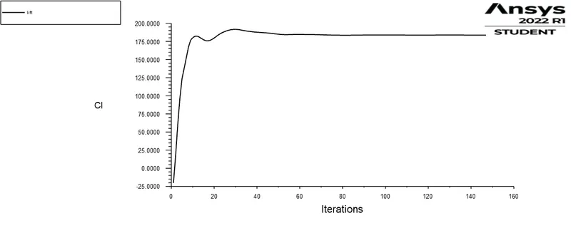
- Define plots, drag coefficients, and lift coefficients at the car wall.
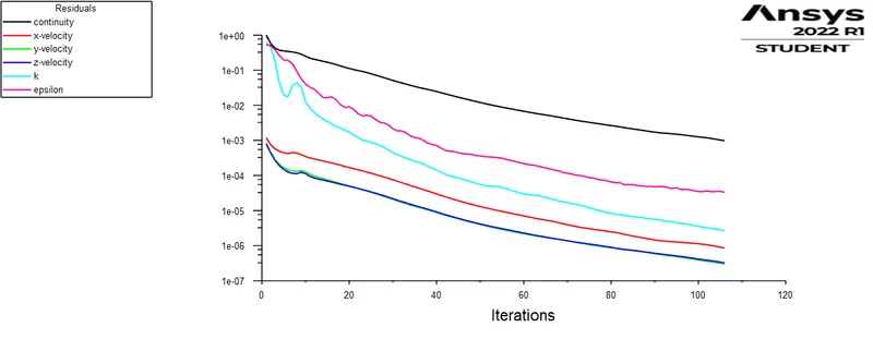
- initialize and run the simulation till gets converged.
Results
|
Mesh type |
No of elements |
Converged at |
Drag coefficient |
Lift coefficient |
|
Coarse |
131103 |
145 |
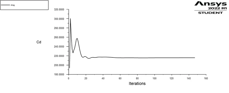
215.804 |
183.69 |
|
Fine |
198631 |
101 |
205.85 |
178.21 |
|
Very fine |
368868 |
107 |
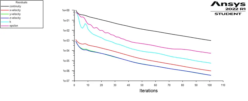
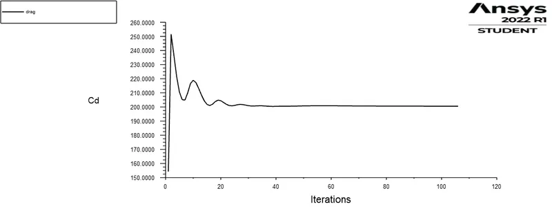
200.55 |
169.97 |
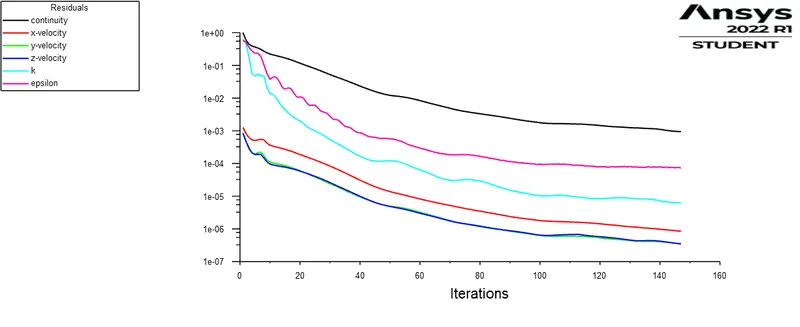
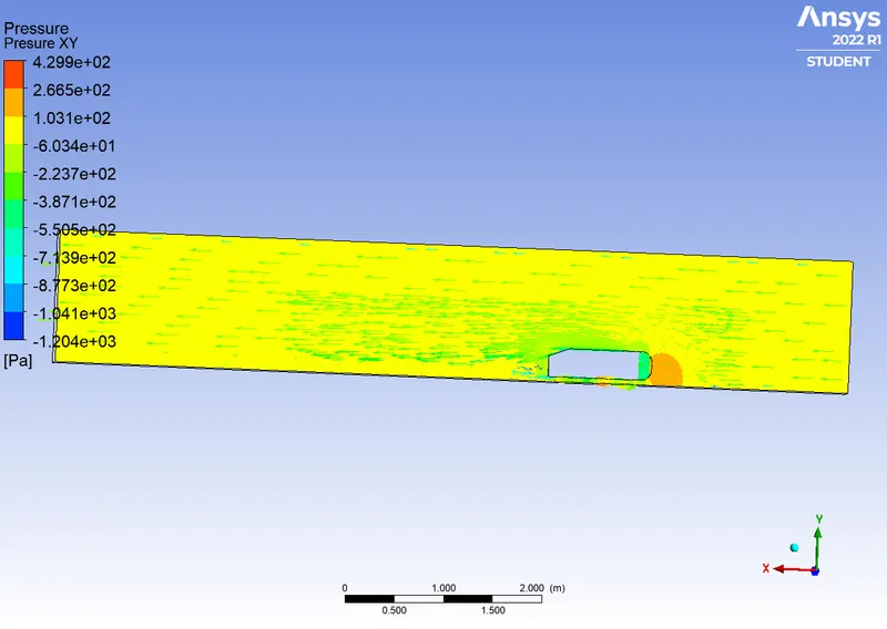
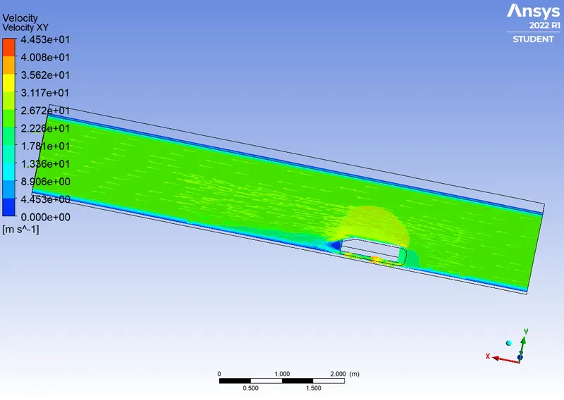
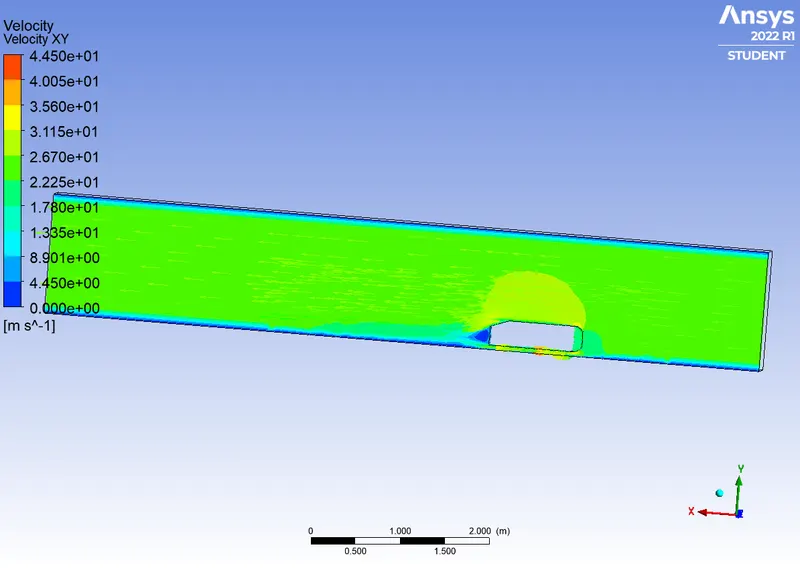
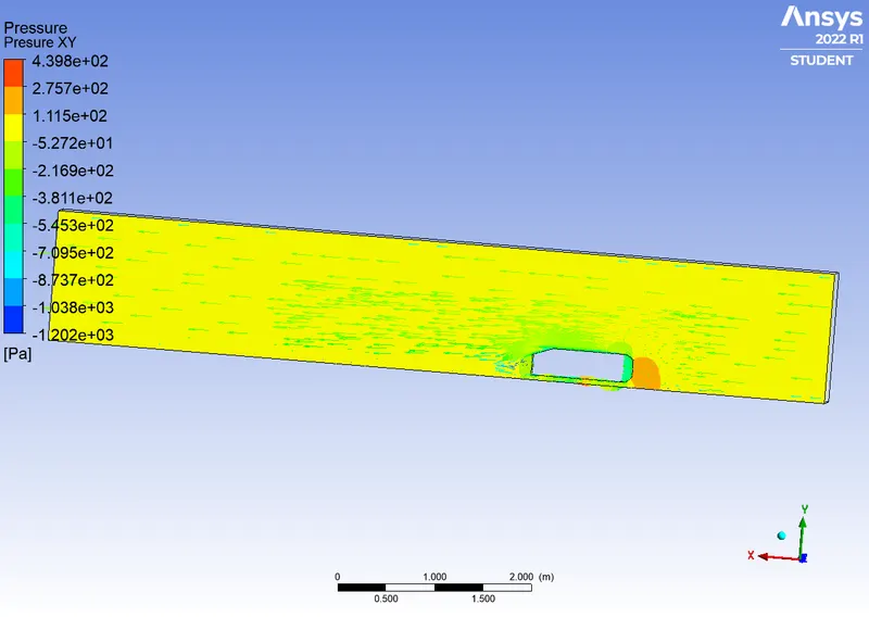
Residual plots, drag and lift coefficient plots, Velocity and pressure plots of different mesh size
Coarser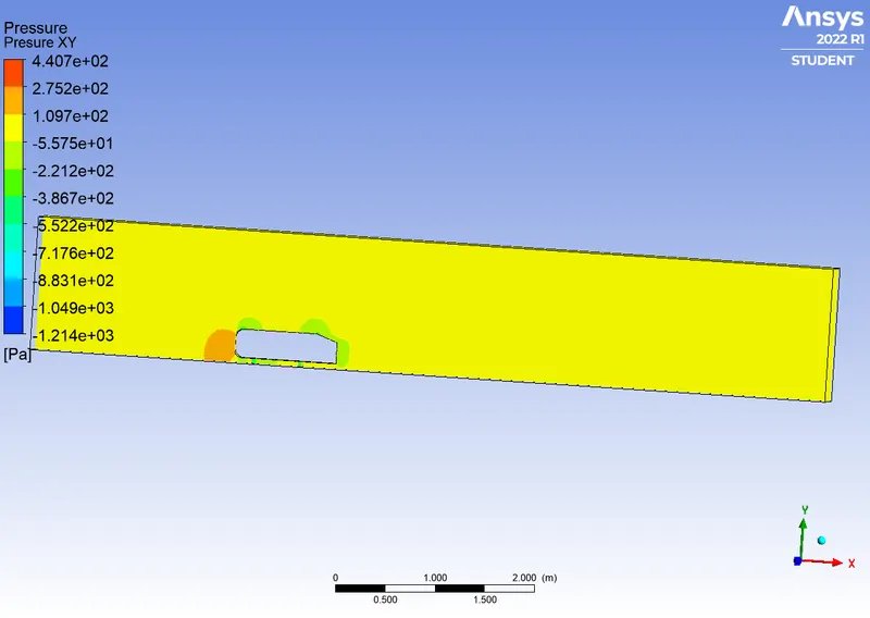
Fine
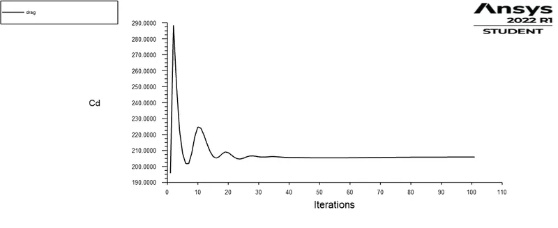
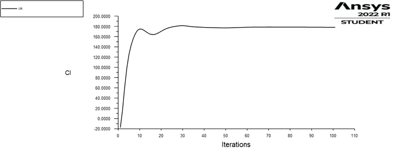
Very Fine
Conclusions
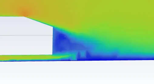
1. Simulation on Ahmed's body was done, found a turbulent region or wake region formed at the end of the body. this region is evident in velocity profiles.
2. grid independent study was made, with an increase in the no of elements --> drag and lift coefficient values are reducing.