Week 3 - External flow simulation over an Ahmed body.
External flow simulation over an Ahmed body
AIM:
To perform the external flow simulation over an Ahmed body with given given geometry.
Explanation:
All ground vehicles can be termed as bluff bodies moving close to the road surface. The analyzed body is able to capture the essential features of the flow which characterize modern cars. Most importantly, high-quality test data are available. The aim of the study is to validate results obtained by steady-state, incompressible turbulent flow in Ansys fluent. We will investigate the flow around the Ahmed body with the slant angle of 20deg and the compare the various cases by Mesh independent study.
Generally The Ahmed body shape provides a model to study geometric effects on the wakes of ground vehicles. Based on the test data, we will validate our simulation model by comparing.
Ansys Workflow:
Since this is a complex geometry, we split this symmetrical body using split body option so we can save the more cells and computational time then we create two computational domains using enclosure for refined analysis.
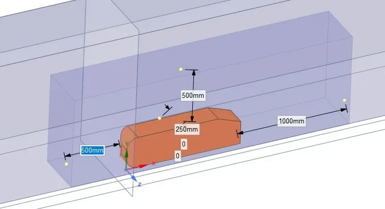
In this challenge as per the requirement here i have taken four cases for Mesh independent study for refined simulations for minimum drag. so we put a constant Ahmed body dimensions and velocity.
Case 1:
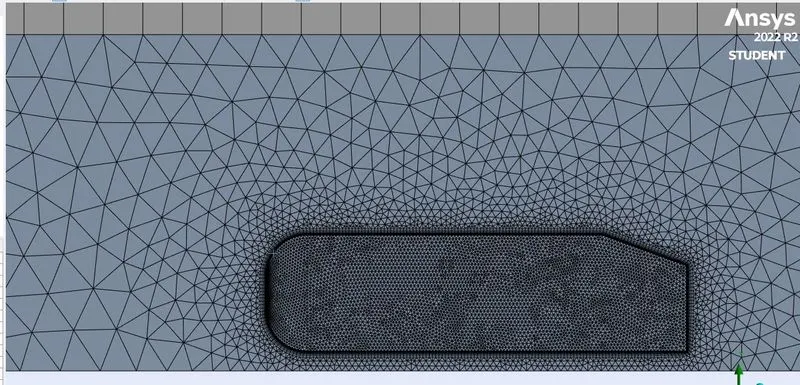
Meshing:
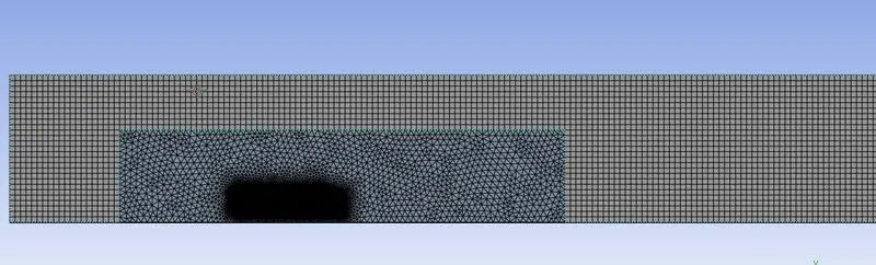
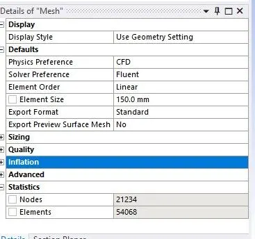
Base mesh size:150mm
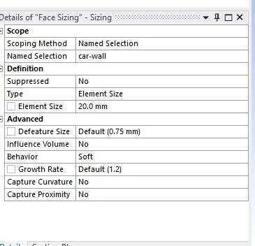
Mesh for car wall =20mm
Inflation layer
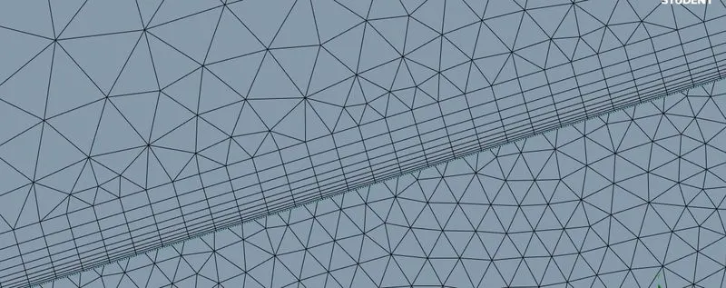
Based on y plus calculator first layer thickness is 0.4mm with 1.2 growth rate, maximum of 10 layers.
Why inflation layer?
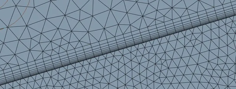
There is a viscous effect dominates near the car wall so velocity gradient occurs, to capture this parameters we have to create fine mesh near to the layers which is structured mesh. we gradually increase the cell height of inflation layer, the first cell height is based on Y plus layers.
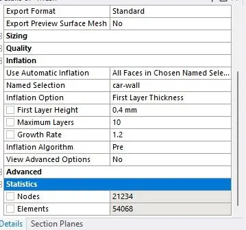
Total number of elements=54068
Fluent setup and Solving
Here we go for k-epsilon turbulent model and the fluid material is air, in boundaries we can set the parameters like velocity, density into the respective zones.
Reference values
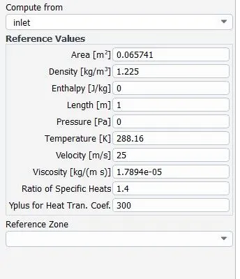
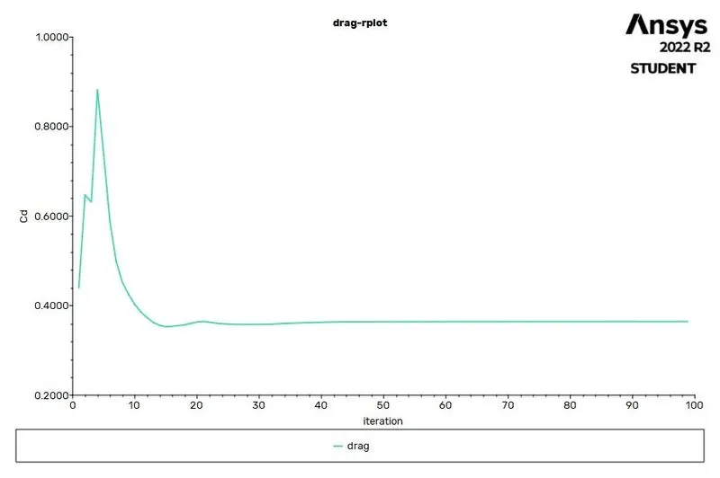
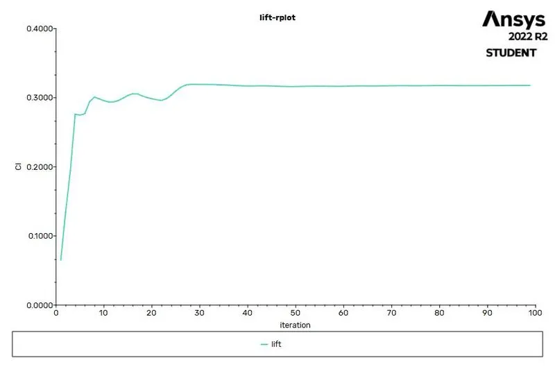
Solution is converged from 99 iterations.
Drag
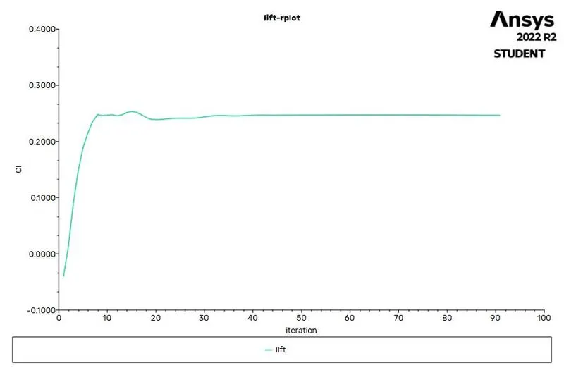
Lift
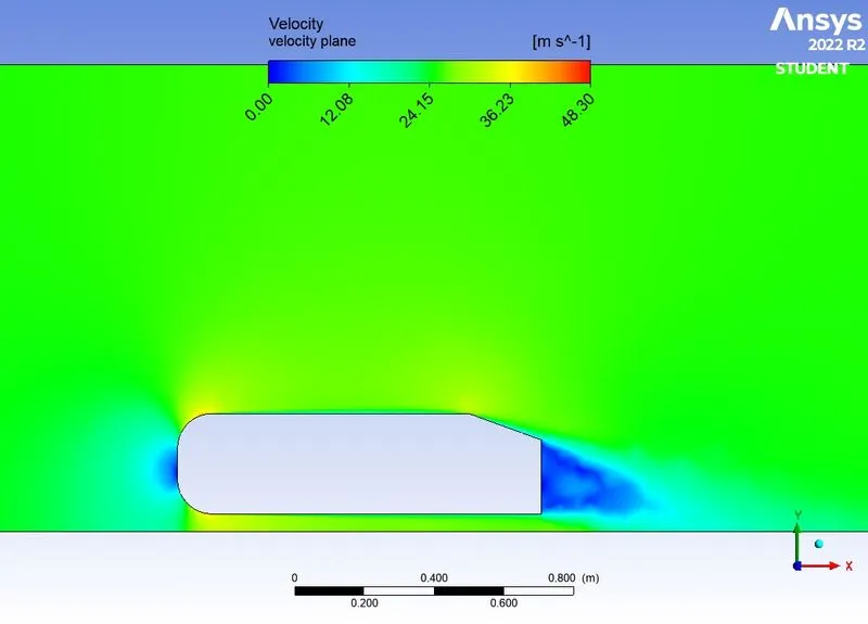
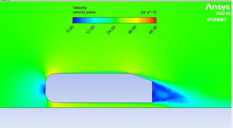
Velocity contour
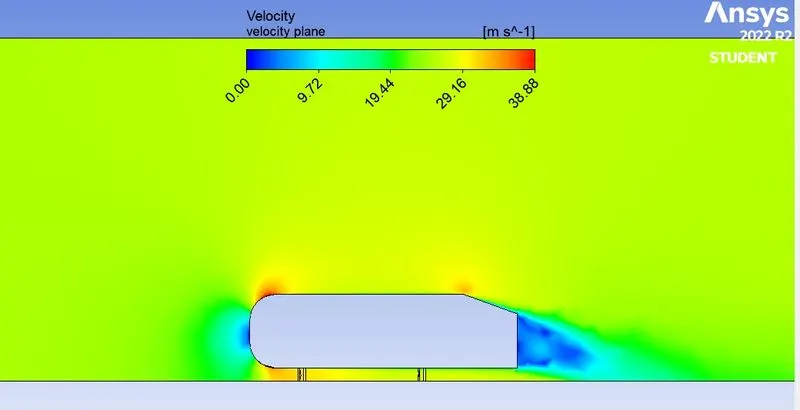
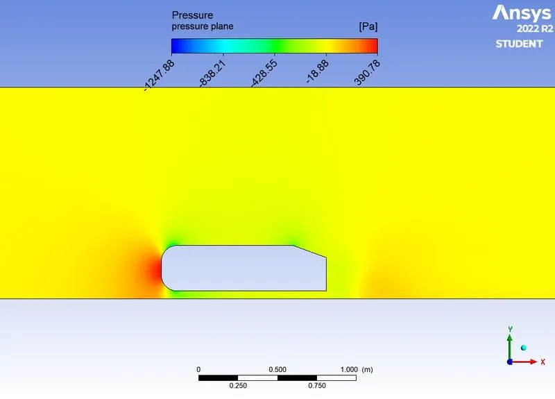
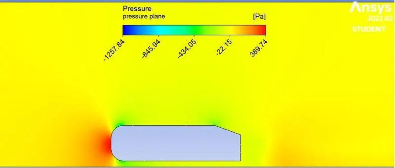
Reason for the negative pressure in the wake region.
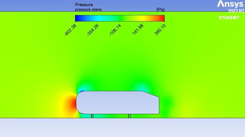
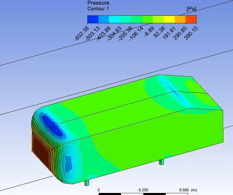
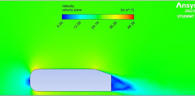
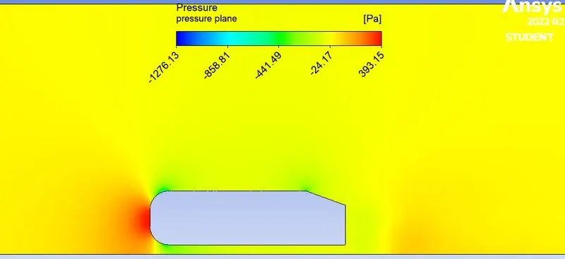
In velocity contour plot we can see the wake region behind the ahmed body which is vaccum with negative pressure and lower velocity. at the leading edge the velocity tends to minimum simultaneously the pressure will be high.
Wake region is previous location of body with respect to time, also it depends to geometry which is how big the wake region is. the wake region is vaccum so that the pressure is negative.
Pressure contour:
Case 2
Base mesh size: 100mm
Car wall mesh size: 15mm
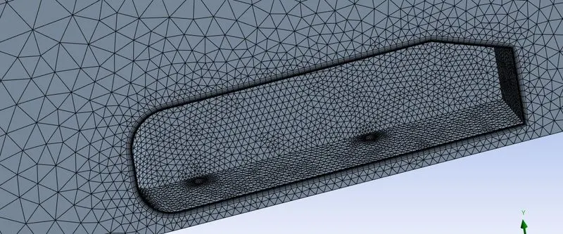
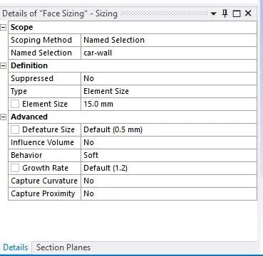
Inflation layer
First layer thick 0.4 mm
growth rate 1.3
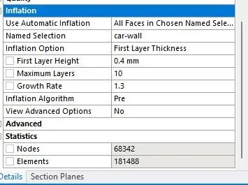
Total number of elements=181488
Pressure contour
Case-3
Base mesh size=50mm
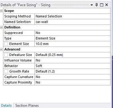
Car wall mesh size=10mm
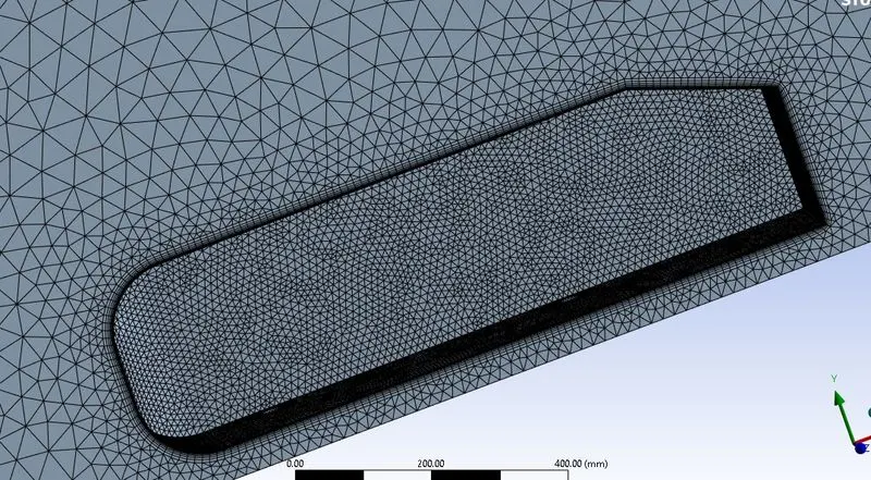
Inflation layers
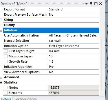
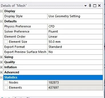
Total number of elements=437697
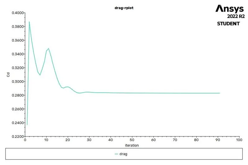
Darg
Lift
Velocity contour
Pressure contour
Case-4
Base mesh size=100mm
Car wall mesh size=8mm
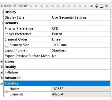
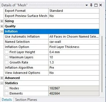
Total number of elements=482664
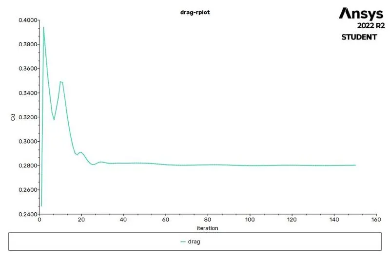
Drag
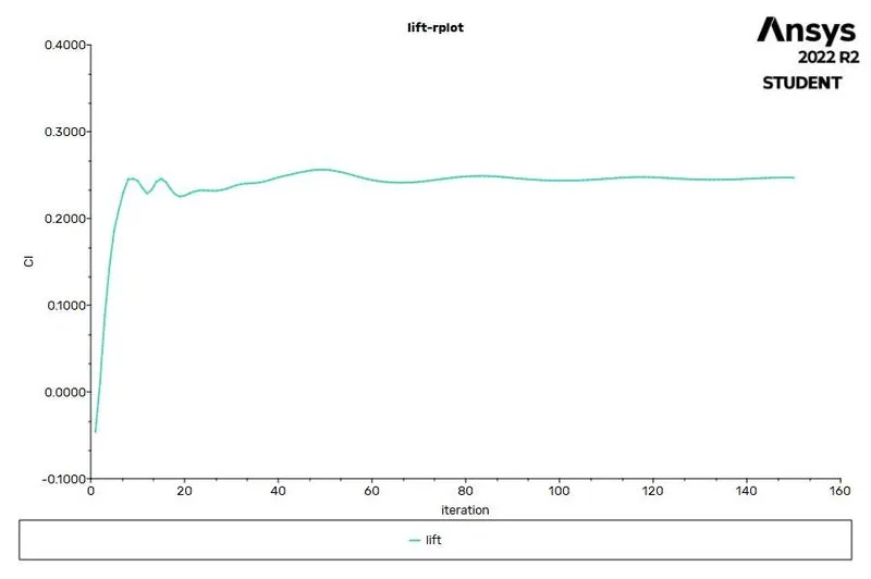
Lift
Velocity
Point of Seperation
Point of seperation is based on geometry shape in this case the slanting angle is 20deg . if we increase the angle, flow seperation occurs earlier. if the flow seperation increases the drag will also increase. by creating vortices we can delay the point of seperation or the vortices helips the flow to be stay attached.
Pressure
Mesh independent study
| cases | No. of elements | Drag | lift |
| coarse mesh | 54068 | 0.36 | 0.31 |
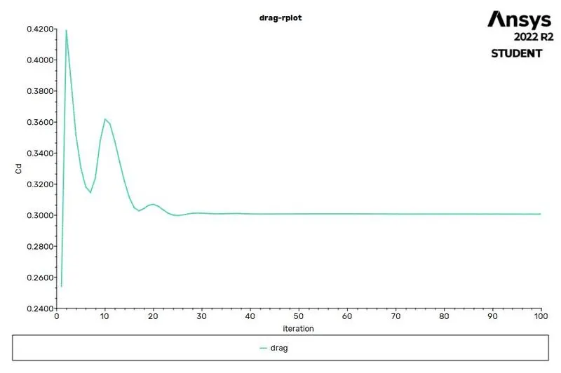
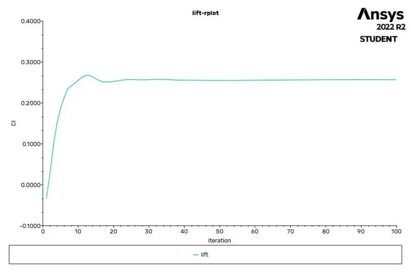
| medium | 181488 | 0.30 | 0.25 |
| Finer | 437697 | 0.282 | 0.24 |
| More Finer | 482664 | 0.280 | 0.24 |
Here we can see that last two cases almost equal but the mesh elements differs and the last case it tooks 150 iterations to converge and more computational time, whereas the third case tooks 100 iterations to converge with less computational time.