Drop test of Smartphone in Ls Dyna
Aim
Create the solver input deck for the drop test of a smartphone
OBJECTIVE
Here we are provided with a only mesh file of the drop test.this file basicallyt contains the mesh.So when we input the .k file in LS Dyna it will be the showing only the ELEMENT,NODE,PART keywords only, becuase the file is having no information for the simulation its just have the info about the nodes and elements in it.Sowe need to create the solver input deck for the droptest and eventually we will be analysing the simulation plots and we will comes to the rpoper conclusions.
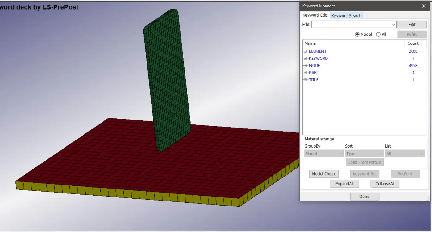
Fig 1 Drop test mesh only file opened in Ls Dyna
Here we can clearly see the model of smartphone which is solid meshed model and a two meshes for mimicking the ground , one is solid mesh and the other one is shell mesh.But for the simulation we will be taking only the shell mesh since if we took the solid mesh that will leads to more computational calculations to be done in behind by solver .So to make the calculations easier and to get the somewhat accurate results we are going with the shell mesh model as the ground.
PROCEDURE
Here we first need to import the only mesh drop test modl into the LS Prepost.For that open LS Dyna > File > Open > browse for the drop test only mesh.k model >Open.This will open the mesh model for the drop test in the LS Prepost.Then we need to delete the
Solid ground part from the model.For that Choose Model on side tool bar area > Select KEYWORD > Choose PART Keyword > Open the part keyword CARD >select the solid ground > delete > Done .This will delete the solid ground mesh from the model.
First we need to create the material for the parts incluidng the smartphone and the rigid ground.We are creating a Linear plasticity MAT_24 material for the Smartphone.Here in Ls DYna there is no unit system.Its always user wish to define the unit system as per our wish.here Since the electronic components are having weight in Grams and the drop test is an impact test and it will be carried out for about 150 milliseconds because the entire impact will happen for maximum for 150 milliseconds.Normally the impact will be end in 120 milliseconds but the rebounding will also happens for the next 30 Milliseconds.
To create the linear plasticity material for phone wwe need to Choose Model on side tool bar area > Select KEYWORD > Choose MAT Keyword > Open the MAT_24 keyword CARD >Select the phone.>Input the values of Rho,E,Etan and Poisson's Ratio in that Card >Accept > Done .Similarly create a MAT_20 Rigid material card for the Ground,since the ground is rigid.Here the ground is rigid so we are giving a high value for the elastic young's modulus.
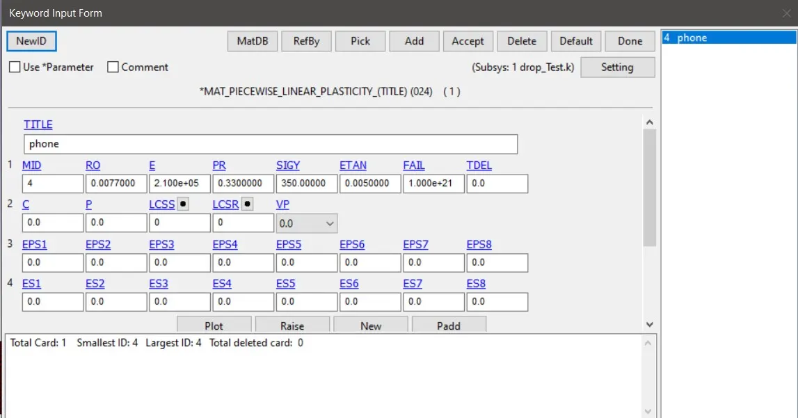
Fig 2 MAT_24 linear plsticity material Card
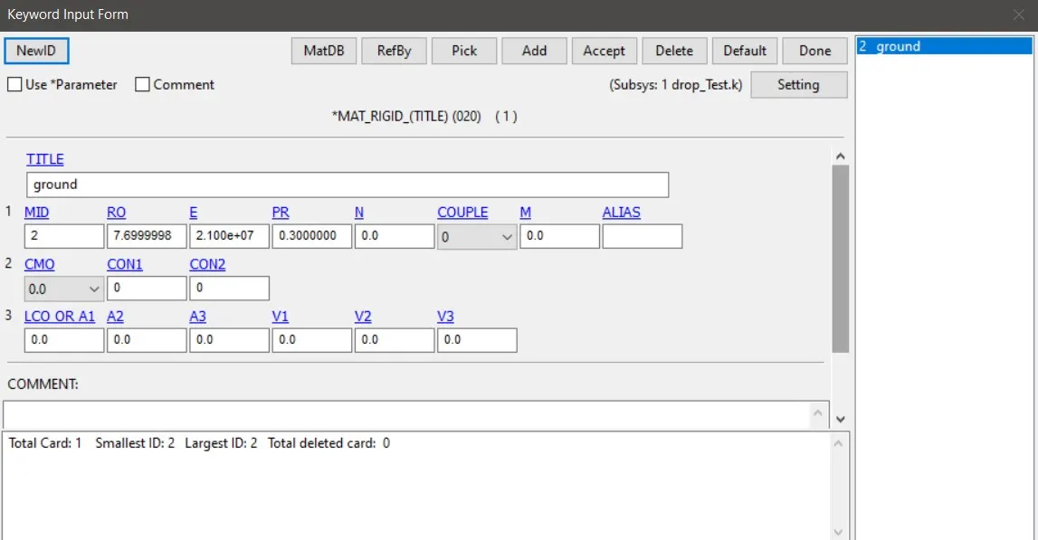
Fig 3 MAT_20 Material card
Then we need to create a section for the shell and solid.This needs to be done using section keyword .We needs to select section for shell element which is for ground and section solid for the Solid elements in Mobile phone.
THis can be done by Model >keyyword>place radio button in all > Section >Shell >Choose th values as shown below > accept >Done
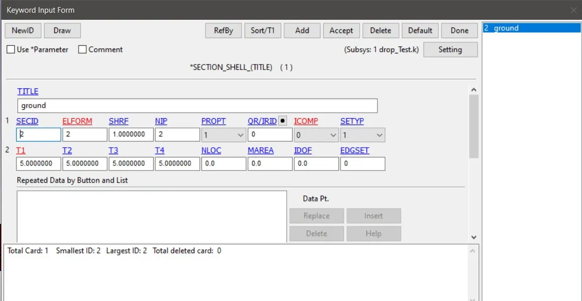
Fig 4 Section Shell card
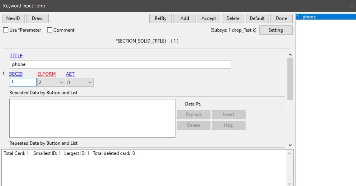
Fig 5 Section Solid card
Then we can open the part keyword and we can asisgn these section and material to the respective parts.this can be done by Model >keyyword>place radio button in all > part > Assign the material and section ID s >Choose th values as shown below > accept >Done
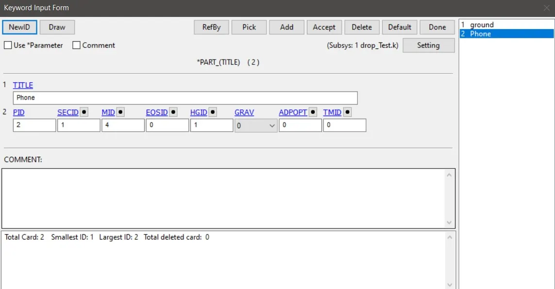
Fig 6 Phone part Keyword Card
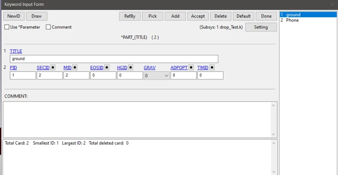
Fig 7 Ground Part keyword Card
Then we need to give the contact and also we need to apply the velocity to the whole phone model.In the contact creation we need to make the contact_Automatic _Surface _to_surface .But for making this contact we need to have a PART SET for the component which we intended to make the contact.To create PART SET we can use Model >Create entity > SET DATA > SET_PART >Place the radio button in Create >pick the part > APPLY.This way we can create the part set for both the ground and phone.Then we can go to Keyword > Choose the radio button in ALL > Choose CONTACT keyword >Select the Contact _ Automatic_ Surface _ to _ Surface. Choose the SSTYPE and MSTYPE as 2 which is basically allows us to selct the part set to create the contact> select phone part set in slave ID and master part set in Master ID > ACCEPT >DONE.
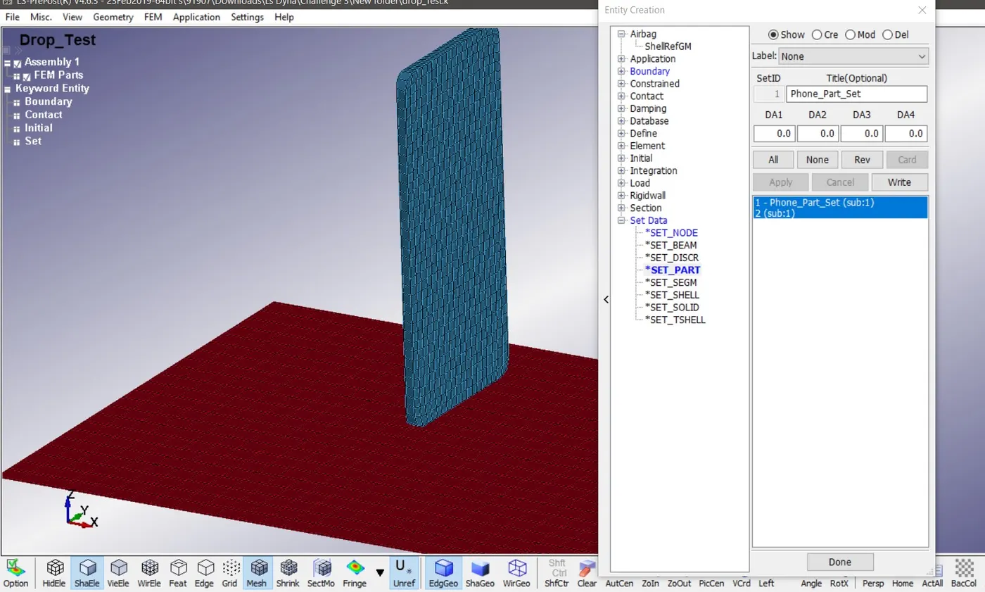
Fig 8 Part- Set creation
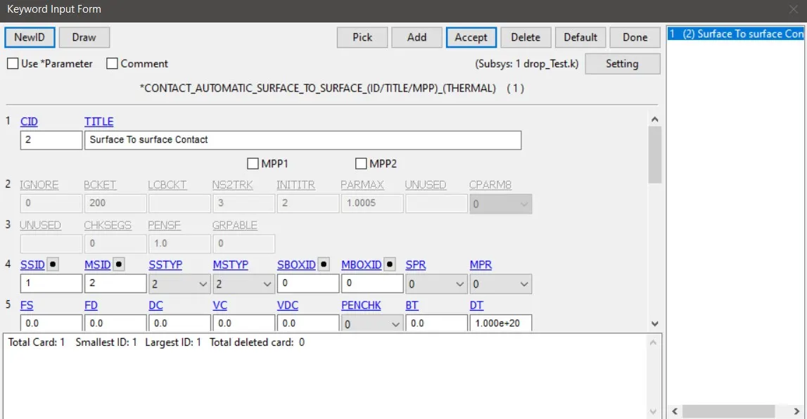
Fig 9 Contact Card creation
Similarly we need to create a NODESET on the mobile phone PART to assign velocity to it.In drop test basically velocity at the point of impact is v = √2gh . But for this to apply we need to have the idea of where the centre of gravity of phone. then only we can adjust velocity at impact by adjusting the height of the phone centre of gravity.But this challenge intends to give us a idea about creating a solver deck from scratch we can give an intial velocity which is constant to the phone until the impact happens.So this can be given by INTIAL > VELOCITY > ASSIGN THE NODE SET ID > GIVE THE VELOCITY AS -5 as the velocity is in negative z axis >ACCEPT > DONE
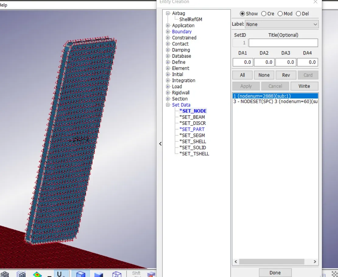
Fig 10 Node-Set Creation
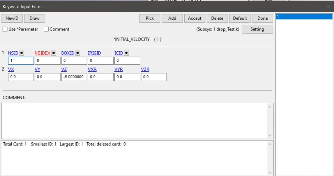
Fig 11 INTIAL VELOCITY CARD
Then need to create a single point constarint SPC on the Ground .For that create entity >Boundary > Spc > pick the nodes at the opposite edges of the ground mesh elements >Apply.This will create a NODE SET with those selected nodes .Then open the INTIAL > VELOCITY>ASSIGN THE NSID >GIVE VELOCITY IN Z AXIS AS -5 mm/ms > APPLY >DONE.
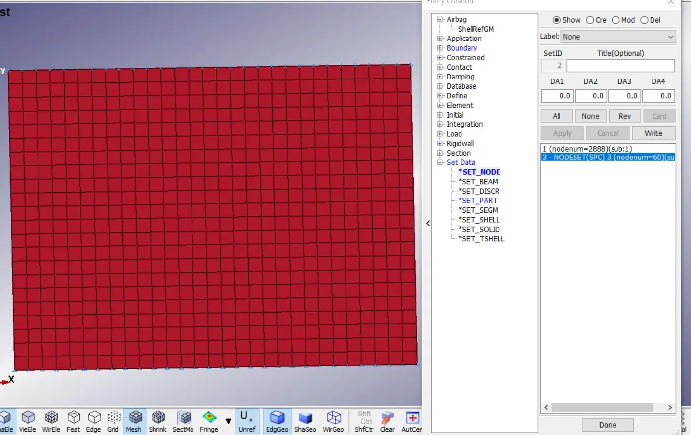
Fig 12 Single point Constraint Node Set
Then we need to set the control termination card .For that Model >Keyword >Control >Termination >set the total time of run as 20 ms .Since we need to generate the plot of the energies of the simulation we need to request for it using the GLSTAT in DATABASE ASCII keyword and set the DT which is th time interval in which the points on the plots are plotted.Similarly to obtain the animation of the simulation we can request for DATABASE > BINARY >d3plot>Set the time interval as dt =.5 ms which means in every 1 ms the simulation is recorded.
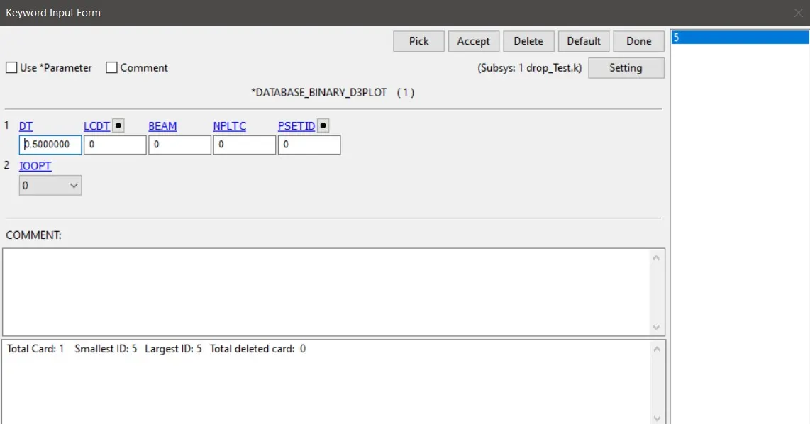
Fig 13 Database Binary D3PLOT Card
simlarly we can request for contact force (RCFORC) ,MATSUM ( which gives the individual parts energies ) etc in the database ascii option card.
This is done by Keyword >place radio button in all >Database >Ascii option >select the glstat ,Matsum ,Rc force >give dt as .5 ms >accept > done
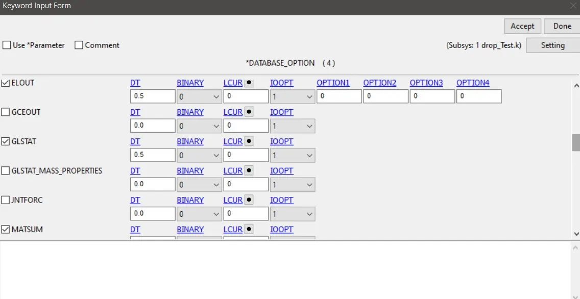
Fig 14 Database Ascii card
Then we need to save the file with the .k extension which is the keyword file extension for the LS Dyna.Then we need to open the lsdyna program manager and open the keyword file in that and then select run.This will run the problems and the results can be post processesed in LSPRepost.
RESULTS(Post Processsing of the Simulation)
Open new LS Prepost >File >Open Binary Plot >Select the d3 plot file of drop test > Open.This will show up the simulation in the Ls Prepost.
Select Fringe component tool on side tool bar > Select stress >choose Von Mises stress >Apply, This will show the Von mises stress stress contour of the simulation.
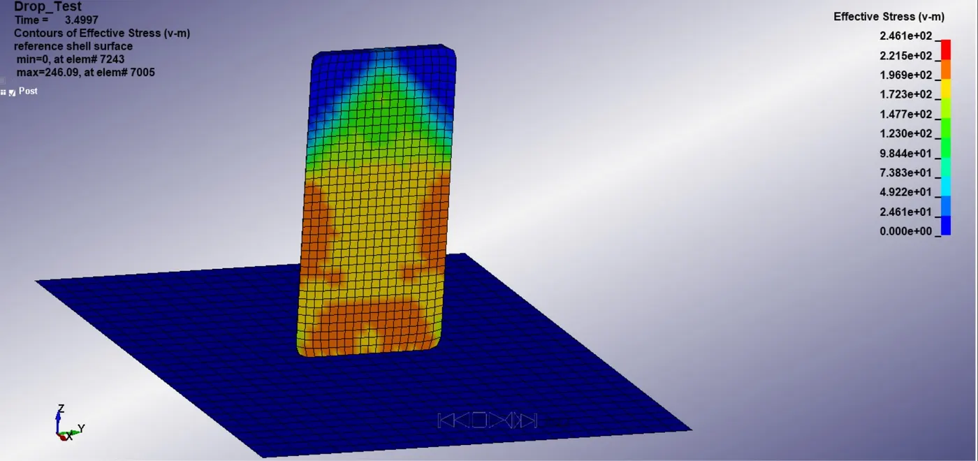
Fig 15 Von Mises Stress distribution in the Phone at the time of impact
Maximum Von mises stress devoloped in the phone is aout 0.24 Pa as the unit system her followed is gm/mm/ms.The stress contour showing is proper we expected the impact region will be devoloping the maximum stress.As the phone suffers the plastic deformation there will be stress devoloped at that point where the kinetic energy is getting converted to the internal energy of the componenet.And the top regions of the mobile phone didint suffers any stress ,that is why the plot showing zero stress at its top end of phone.
We ned to choose the ASCII plot tool on side tool bar > Choose glstst or Matsum >Load the respective file >choose the enrgies we need to plot > choose the part > select plot.This will plot the graph we request.
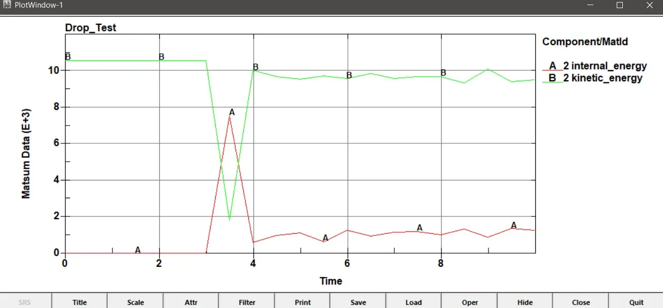
Fig 16 Matsum plot of kinetic energy of Phone
This shows the indication of the plastic deformation happens at the 3 ms time.At that region we can see the rapid falling of KE and the same time the internal energy is getting at its peak satisfying the law of conservation of energy of the phone.Maximum Kinetic energy is 7.4 x 10^-3 gm mm^2/ ms^2( at the peak) Similarly the maximum value of the internal energy is at 2 x 10^-3 gm mm^2/ ms^2( at the peak).
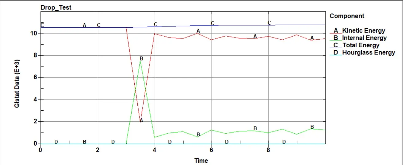
Fig 17 Energy GLSTAT Plots of the Drop Test
First way of debugging an implicit analysis is by looking at the plot of energies in the analysis.So we can check the energy plot of the drop test .In this plot we extracted the internal energy ,kinetic enrgy,hourglass enrgy and the total energy of the simulation.Here as we can see from the graph that as the conservation of energy law states the Total energy of the simulation is constant .As the mobile phone cames down the only kinetic energy is with phone as the ground is rigid.So the kinetic energy of phone will be reduced as soon as the phone hits the ground at the time equals 3 millisecond and the lost kinetic energy is getting converted into the internal energy of the component as the material will gets deformed by absorbing some little amount of energy.Since we use the hourglass control card and good element formulation for the elements in the model the hourglass energy is nearly equals to zero.So simulation results makes sense.
Conclusion
From the simulation we get to see the process of setting up of the solver deck for the drop test of the mobile phone.When an impact happens the maximum stress will be devoloped at the time of impact,that small miliseconds lasting duration will cause the maximum stress and strain happens to the object which makes the impact.After the impact there will be some KE left with the object ater the conversion to Internal energy, so with that the object will be rebounds back.If the crash is very rapid like the entire kinetic energy is getting fully converted into internal energy by the huge deformation affected to the componenet then there will be minimal rebbounce after the impact and that may not be visible to eyes.