Week - 3 Drop test Challenge
Drop Test of Cell phone on plate
AIM:
- To perform a drop test simulation of a cell phone dropped on a plate under initial velocity using LS-Dyna.
OBJECTIVE :
- To create the simulation file (input file ) from the given K format type of file.
- To create the material card.
- To create a section card.
- To assign material and section card to the part.
- To create the boundary conditions for plate.
- To assign initial velocity to the phone.
- To assign control termination card.
- To create a contact interface between cell phone and plate.
- To define the output database as both binary D3 plot and ASCII.
- To check-up the model and run the simulation.
PROCEDURE:
STEP 1 : Import the file
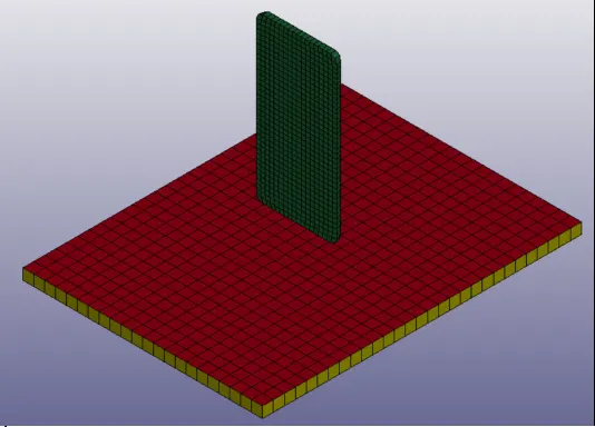
- imported the f format type of drop test file using LS-Prepost software.
- File > Import > LS-Dyna keyword file > browsed to selected the K type of file > imported it.
STEP 2 : Check the keywords
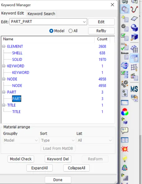
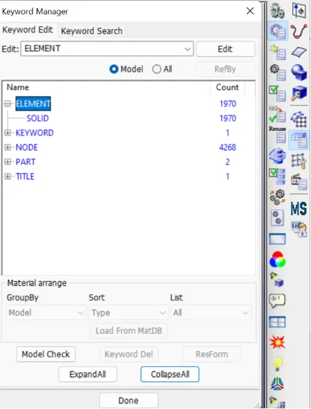
1. Both shell and solid elements are presented in the model .According to analysis solid elements only needed other shell elements remove from the model
STEP 3 : Create the material card
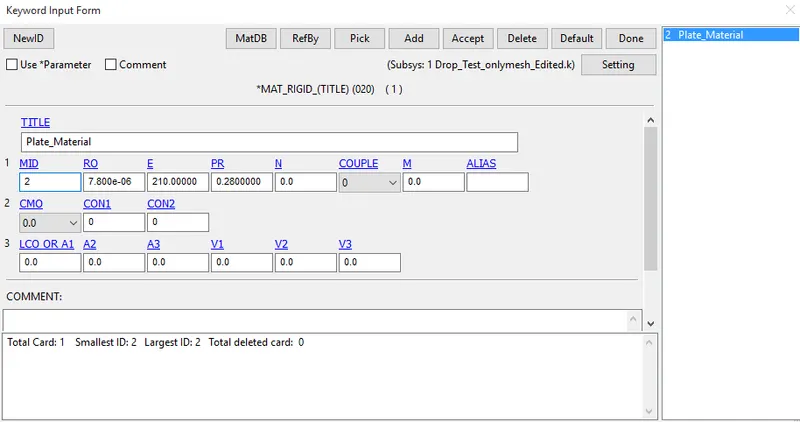
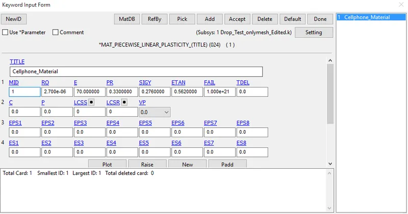
For cell phone part has assigned the material is 024 PIECEWISE_LINEAR_PLASTICITY and plate part has assigned the material is 020 RIGID.
STEP 4 : Create the section card
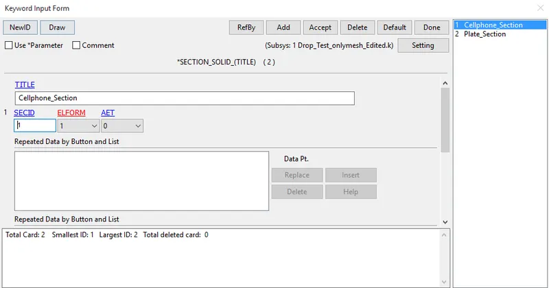
Side bar > model and part > keyword manager >all > solid > created the new SECIDs for both parts.
STEP 5 : Assign the material card and section card to the parts.
Side bar > model and part > keyword manager >model > part > assigned the MID and SECID cards to their respective parts
STEP 6: Create the boundary condition for plate
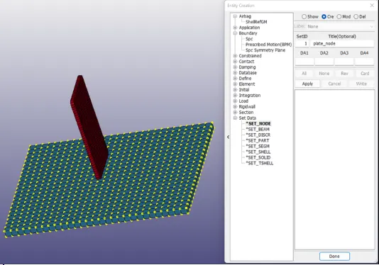
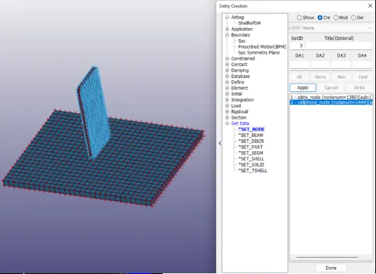
Side bar > model and part > create entity > set data > set node > selected the nodes by area in plate > node set created for plate > title name as plate_node > done.
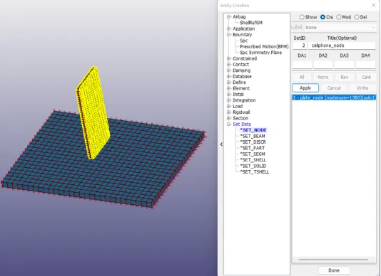
Side bar > model and part > create entity > set data > set node > selected the nodes by area in cellphone > node set created for cellphone> title name as cellphone_node > done.
STEP 7: Assign the boundary condition to the plate.
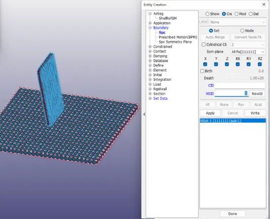
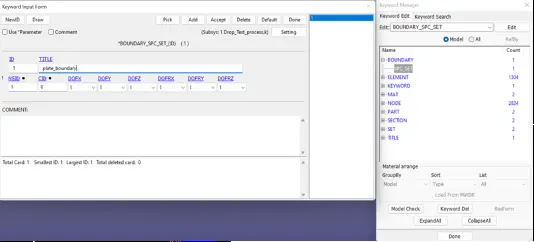
Assigned the boundary condition to plate is by using, side bar > model and part > create entity > boundary > Spc > create > set > all fix [111111] > specify the node set id value for plate is 1 > selected the nodes by area > apply > done.
STEP 8 : Assign the initial velocity to the cellphone
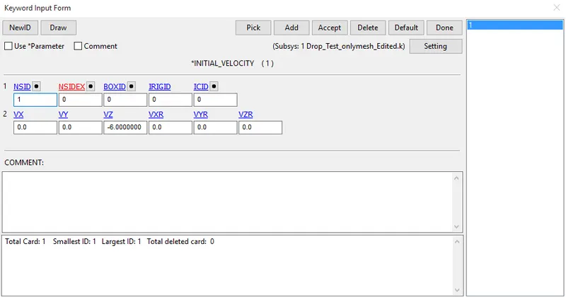
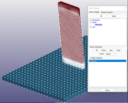
Create initial velocity to selected set nodes for ceel phone.
Side bar > model and part > keyword manager > initial > velocity > selected the nodeset id for cell phone > specify the initial velocity value is 6 mm/ms > accept and done.
STEP 9: Assign the control termination card
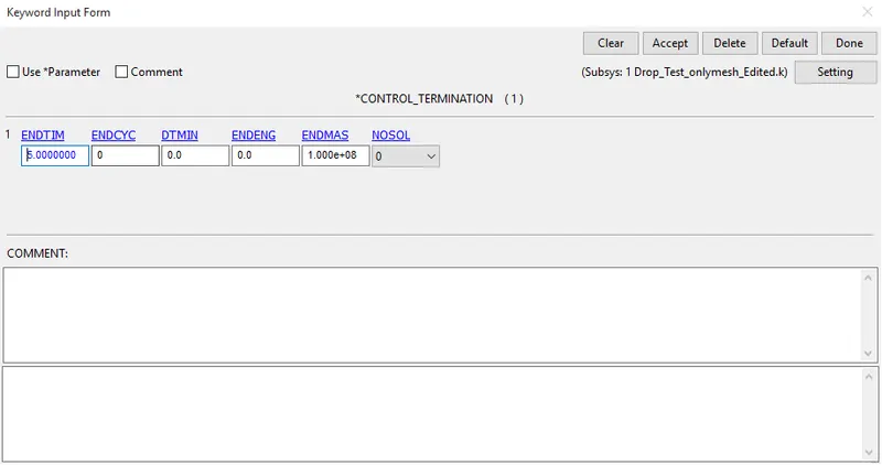
In order to assign the control termination card by the following steps.
Side bar > model and part > keyword manager > control > termination > specify termination time is 5ms > accept and done.
STEP 10 : Create a contact interface between the cellphone and plate.
Side bar > model and part > create entity > set data > *SET_SEG > selected the elements by area > plate_segment created.
Side bar > model and part > create entity > set data > *SET_SEG > selected the elements by area > cellphone_segment created.
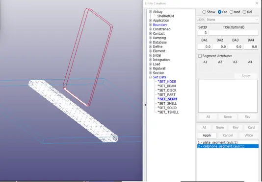
In order to create the contact card by the following steps.
Side bar > model and part > keyword manager > CONTACT > selected AUTOMATIC SURFACE TO SURFACE > selected plate_segment as a master and cellphone_segment as a slave > accept & done
STEP 11 : Define the output database as both BINARY D3PLOT AND ASCII
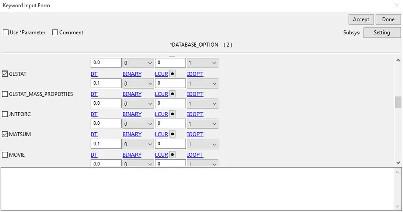
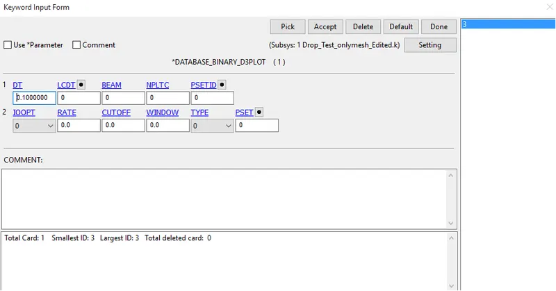
DATABASE_BINARY_D3PLOT ensures d3 plot files which its stores stress strain contour of the entire deformed model.
In order to create the DATABASE_BINARY_D3PLOT by the following steps.
Side bar > model and part > keyword manager > database > select DATABASE_BINARY_D3PLOT > provide DT value is 0.1 is a time interval between output states > accept & done.
STEP 12 : Model check up
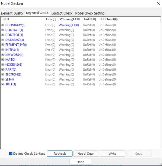
The model is checked for any errors before solving using model checker.
After all the errors are cleared, the drop test setup is saved and is ready to run in LS DYNA manager for solving the scenario.
Warnings we can ignore . once model check is run , it will look like as shown in picture below.
STEP 13 : Run the simulation
To run the drop_test_cellphone_plate file using LS-run by the following steps.
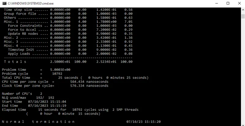
Title bar > file > run LS-dyna > runned the drop_test_cellphone_plate file > achieved normal termination. it means the model is ready for post-processing.
During simulation run window will pop up as shown in picture below.
 STEP 14 : Post processing
In order to see simulation results , we have to open output file in LS-Prepost by the following steps.
In LS-prepost -Title bar > file > open > LS -Dyna binary plot > selected the d3 plot file > visibled to see animation file.
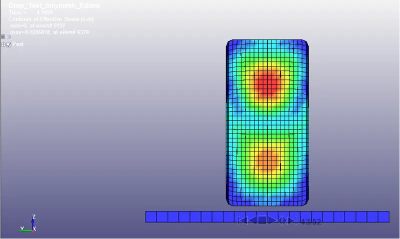
For plot the stress contour , go to sidebar > post >fringe component > selected in which results need for analysing the problem.
For energy plot results , go to side bar > post > ASCII > selected in which enegy results (Glstat and Matsum) need for analysing the problem.
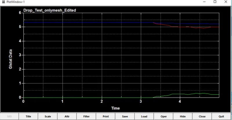
Initial velocity is maximum therefore kinetic energy (RED LINE) is also maximum .But during the cellphone impacted on the plate , the kinetic energy absorbed by the part and it decreases.
Simultaneously before the cellphone impacted on the plate the internal energy (GREEN LINE) in minimum, then after during the cellphone impacted on the plate the internal energy absorbed by the part and it increases.
RESULT :
- Performed a drop test simulation of a cell phone dropped on a plate under initial velocity using LS-Dyna.
- Maximum effective stress is 0.0286 kg/mm^2.
- Energy plot has been plotted as per the required simulation outputs.