Week - 3 Drop test Challenge
Aim:
- To perform a simulation for the "Mobile Drop Test" on the floor and analyze the results in "LS-DYNA".
Introduction:
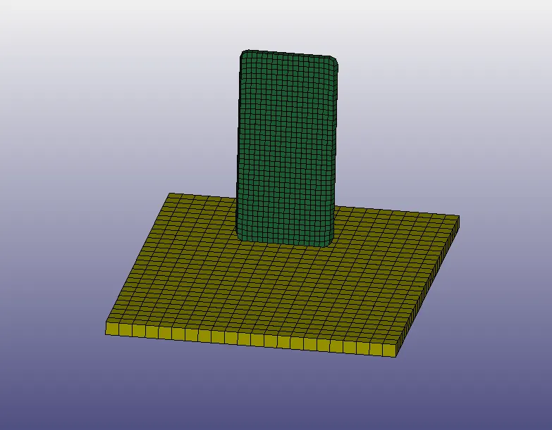
- A meshed model containing 3 components was provided in the challenge in the '.k' file format. The 3 components were the mobile phone with solid elements, floor with shell elements, and another floor with solid elements.
- Out of these two types of floors, anyone had to be chosen for the simulation. The mobile was modeled in the upright direction and was supposed to be impacted on the floor in the downward Z direction.
- The whole case set-up had to be done for this simulation. This included the part, segment, and set creation, material creation, contact definition, boundary condition definition, assigning some initial velocity to the mobile in order to impact it on the floor, and some other parameters like time step, termination time, etc.
- This drop test for the mobile phone has been carried out according to the military standards 810G (MIL-STD-810G). It is a series of tests on equipment with its "tailoring environmental design and test limits to the conditions that it will experience throughout its service life". It consists of several types of tests but in this challenge, the drop test has to be focused, in which a phone is dropped from a height of 4ft or 1.219m.
Procedure:
- The model was provided in the '.k' format and was opened in the "LS-DYNA" Pre-processor.
- The image below shows the actual model with the three parts, the mobile phone, the shell meshed floor, and the solid meshed floor.
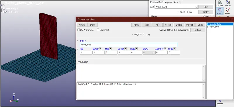
- After importing the model, it was observed and the three parts were defined accordingly. This was done by using the '*PART' keyword from the 'keyword manager', in which the part title was defined to their respective components. Out of the two types of floor, anyone had to be used for the analysis. Hence the shell meshed floor was selected for the analysis and the solid meshed floor was deleted. The image below shows the *PART_TITLE definition.
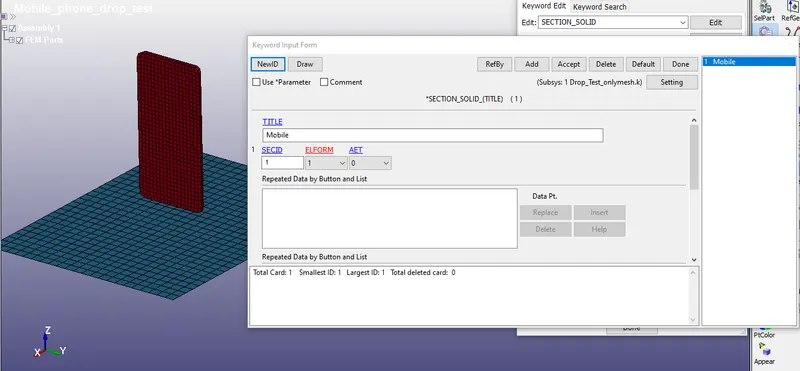
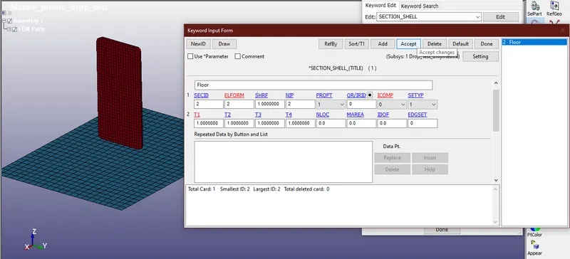
- Later the *SECTION was defined for both the components. For the mobile phone, as it had solid elements, the *SECTION_SOLID was defined, and for the floor *SECTION_SHELL was defined from the 'keyword manager'. All the components in the keyword were kept as default. But in the shell keyword, the thickness of the floor was defined as 1mm. The image below shows the section definition for both components.
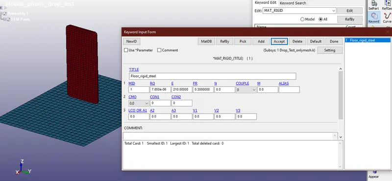
- After defining the sections, the materials had to be defined for both the components. The floor was defined as a rigid component of steel by using the *MAT_RIGID (020), as deformation is not desirable for the floor. The properties of the material were set as the default material of the steel with a density as 7.85e-06 kg/mm^3, Young's Modulus as 210 GPa, and Poisson's ratio as 0.30. The image below shows the rigid material card for the floor.
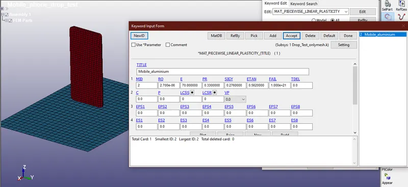
- The mobile phone, on the other hand, was defined as an aluminum solid, by using the 024 PIECEWISE_LINEAR_PLASTICITY card which is an elastoplastic material, since the mobile phone may be deformable in nature. The material properties were set as default aluminum properties. The density was set as 2.70e-06 kg/mm^3, Young's modulus as 70 GPa, Poisson's ratio as 0.33, Yield stress (SIGY) as 0.276 GPa, and Tangent Modulus (ETAN) as 0.562 GPa. The image below shows the aluminum card.
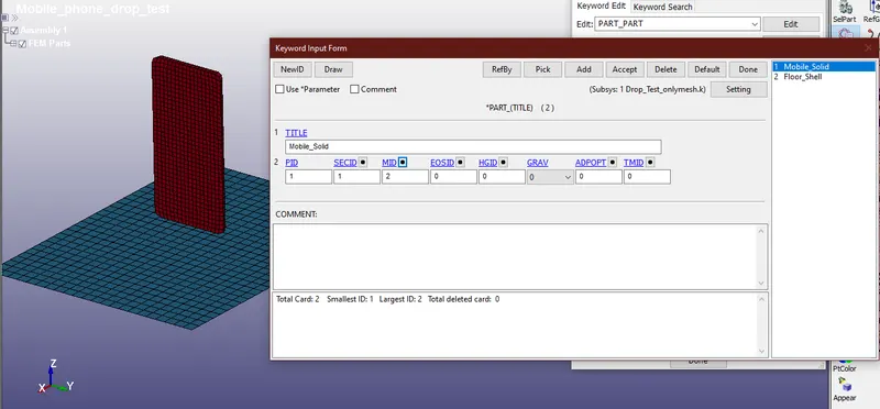
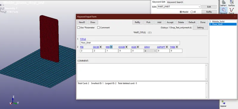
- After defining the section and the material keywords, they were specified in the *PART for both the components. This would associate them with their respective components. The image below shows the definition of the keywords.
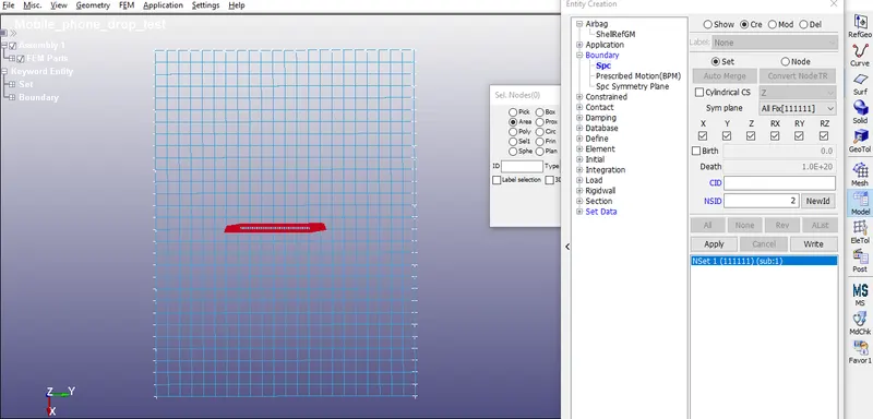
- The next step was to define the boundary conditions to the floor and the mobile phone. The floor is defined as a rigid body and should ideally be non-deformable. Hence it had to be constrained in all three directions and in all 6 degrees of freedom i.e. 3 translational DOFs and 3 rotational DOFs. This was done from the 'create entities' option. The 'SPC' entity was selected 'boundary', and all the end nodes from the 4 directions were selected from the 'area' option and the 6 DOFs were constrained. The image below shows the entity creation.
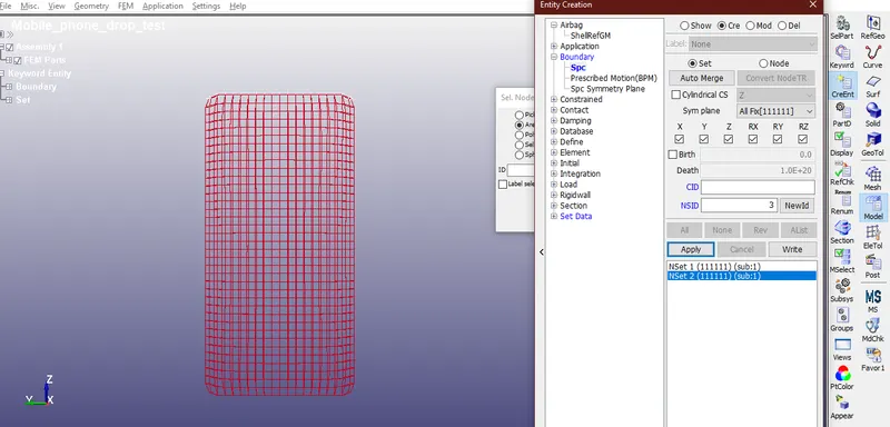
- Similarly, the constraints were also set for the mobile phone. The mobile phone was supposed to impact the floor in the downward Z direction. Therefore, the top nodes of the mobile phone were selected in the 'SPC' entity and since it had to move in the -Z direction, all the DOFs were constrained except the Z.
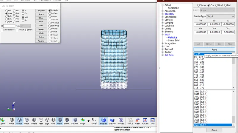
- According to the MIL-STD-810G, the phone is dropped from a height of 4ft or 1.219m. But in this case, the distance between the phone and the ground is very less. Therefore instead of impacting the phone from 4ft, a velocity of a fall of that magnitude was imposed on the phone. This would result in the same impacting scenario and would mimic the fall. The velocity was calculated by using the formula 2gh">√2gh. The height 'h' was entered as 1.219m and the velocity came as 4.94mm/ms. An 'initial velocity' entity was created from the 'create entity'>'initial>'velocity'. All the nodes of the phone were selected and the calculated velocity was imposed as a '-' sign for the downward direction in 'Vz'. The image below shows the velocity creation.
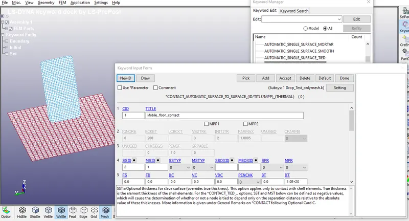
- After imposing the velocity, contact had to be created between the mobile phone and the floor. For this, an 'automatic surface to surface' contact was created between the two components. From the 'keyword manager', the '*CONTACT' keyword was selected and in that, 'AUTOMATIC SURFACE TO SURFACE' was selected. The slave and master set nodes were created. The slave set was defined for the mobile phone since it was deformable in nature, and the master set was defined for the floor since it was rigid.
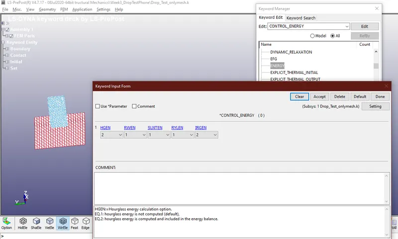
- From the '*CONTROL' keyword, 'energy' was selected. In the 'HGEN', EQ.2 was selected in order to compute the hourglass energy and include it in the energy balance.
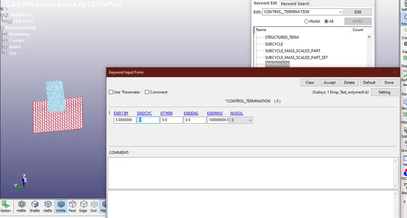
- Later the termination time had to be defined using the '*CONTROL_TERMINATION'. Termination time is one of the most important keywords in LS-Dyna which has to be used for every single analysis. Termination time is the time for which a simulation would run. In this case, the termination time was set as 5sec as seen in the image below.
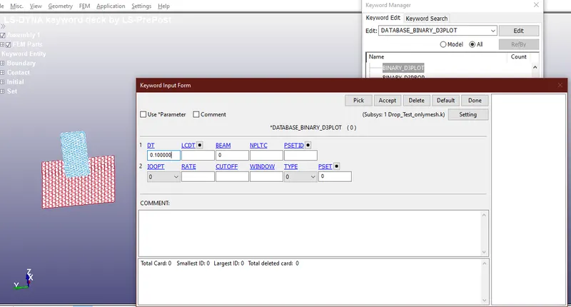
- The outputs of any simulation are requested through the '*DATABASE' keyword. In this, the 'd3_plot' and the ASCII outputs like the GLSTAT, MATSUM, ELOUT, etc. give values of different types of energies, stresses, strains. The d3_plot contains the history of the geometries of the model. The value of DT is set as 0.1 sec, which means the history of the geometries would be plotted after every 0.1sec.
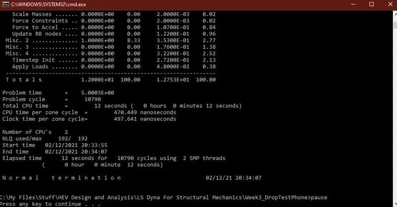
- After all, the keywords were specified and the materials and the contacts were defined, the keyword file was saved, and the "LS-RUN", keyword file was imported and was run for analysis. After 12 secs, the calculations were completed, and a d3plot file was generated.
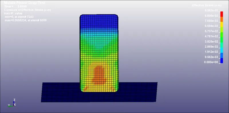
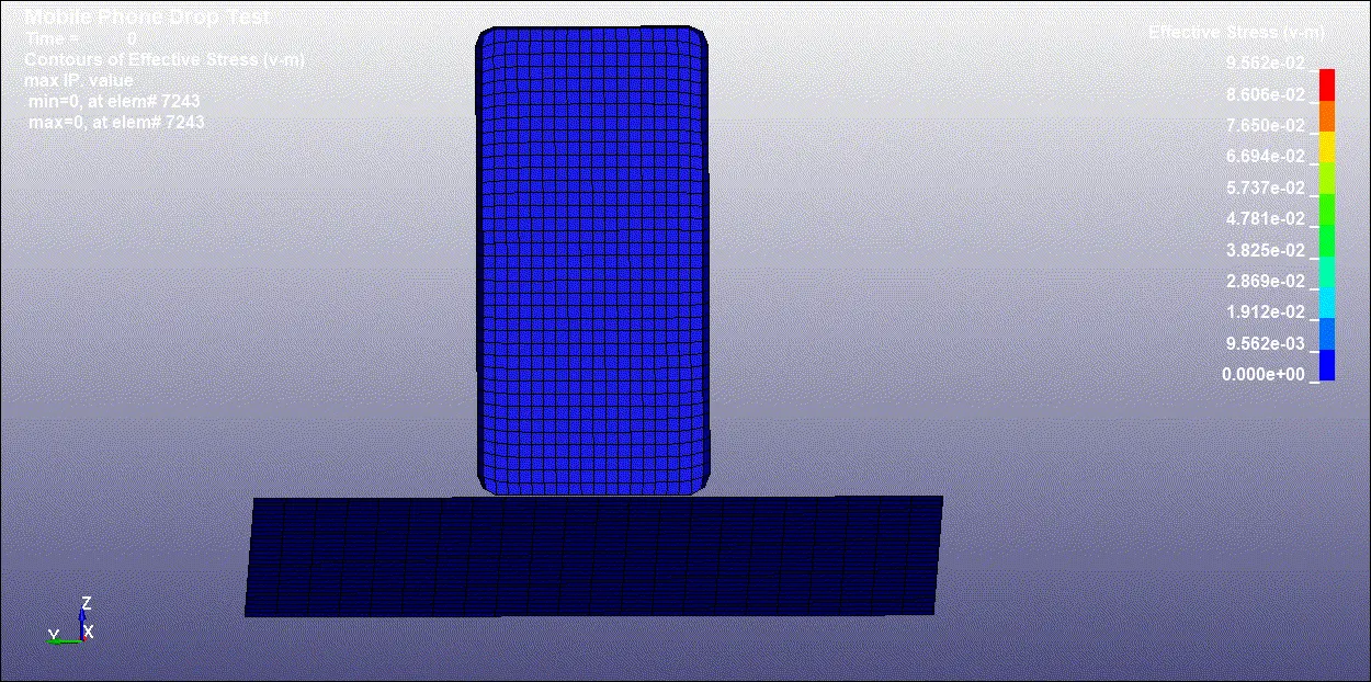
- The d3plot file was opened in the LS-PrePost and the simulation was run. After observing the simulations, the stresses and strains were plotted. The image below shows the von-misses stress and its maximum value along with its simulation.
Results and Conclusion:
- In this challenge, the drop test of the mobile phone was simulated and analyzed successfully. The model which was provided for the analysis was pre-meshed. But the case setup was done in "LS-DYNA". The parts were specified separately, along with the material definition, contact definition, velocity imposition, etc.
- The mobile phone was imposed with a velocity of 4.94mm/ms. This velocity was calculated according to the drop height of 4ft or 1.291m which is specified by the military standard 810G.
- The image below shows the plot for the Internal energy, Kinetic energy, and Total energy, and Hourglass energy. It is clear that when the mobile phone is hitting the floor, there is a sharp drop in the Kinetic energy of the mobile phone. At the same instance, the Internal energy which was 0 before the contact of the phone and the floor, also spikes up sharply, while the total energy of the model remains constant which is desirable. On the other, there is hourglassing in the model, but the hourglass energy is very low/negligible, but it may induce some energy errors.
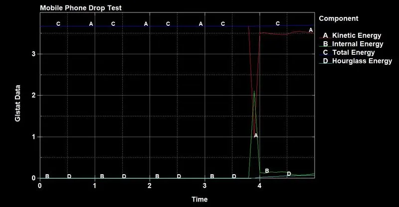
- It is quite evident from the results above that the mobile phone made of aluminum should survive a drop of this intensity.