Week - 3 Drop test Challenge
AIM :
To create a complete simulation file using Input Parameters from this to perform a drop test and Plot the Output results.
OBJECTIVE :
--> Input Parameters required for the simulation are listed below,
- Title Card,
- Section,
- Material Card,
- Part,
- Initial Velocity,
- Boundary Conditions,
- Contact,
- Control Card
--> Plot the Ouptut results such as Vonmises Stress & Energy Plots.
PROCEDURE :
1. Import the given Model in LS-PrePost using File-->Open-->LS-DYNA Keyword File option.
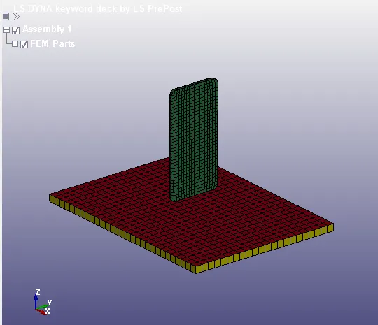
Fig: Imported Model
2. After Importing a Model, Set the Input Parameters using Model-->Keyword Manager option.
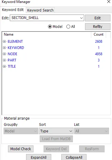
Fig: Keyword Manager
Title :
3. Create a Suitable Title for the simulation by using Keyword Manager-->Model-->Title option,
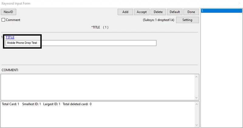
Fig: Creating a Title
Section :
4. Create a Section for Bottom Plate(Shell) and Phone(Solid) part.
5. Go to Keyword Manager-->All-->Section-->Shell option,
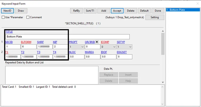
Fig: Section for Bottom Plate (Shell)
6. Go to Keyword Manager-->All-->Section-->Solid option,
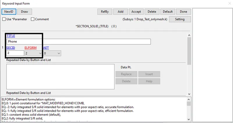
Fig: Section for Phone (Solid)
Material :
7. Create a Material for Bottom Plate and Phone.
8. Go to Keyword Manager-->All-->MAT-->020-Rigid option,
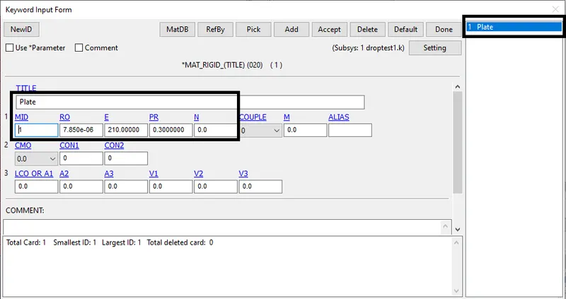
Fig: Creating Rigid Material
9. Go to Keyword Manager-->All-->MAT-->024-Piecewise Linear Elasticity option,
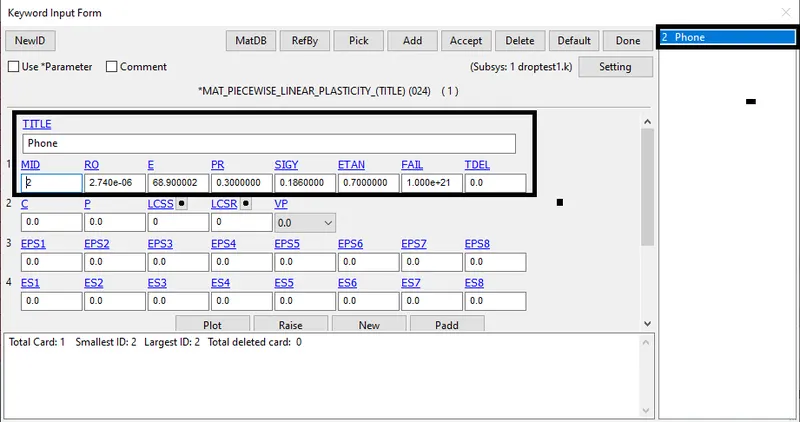
Fig: Creating Piecewise Linear Elasticity Material
Part :
10. Create a Part by using Keyword Manager-->Model-->PART option and assign the Section ID & Material ID,
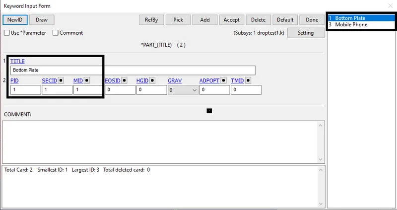
Fig: Creating a Part for Plate & Phone
Initial Velocity :
11. Create an Initial Velocity for Phone by using Keyword Manager-->All-->INITIAL-->Velocity option,
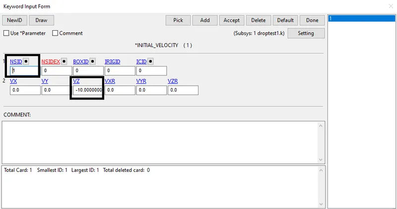
Fig: Creating Initial Velocity
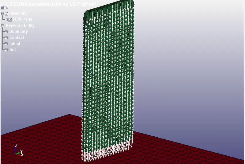
Fig: Velocity towards Z-direction (negative)
Boundary Conditions :
12. Create a Boundary Conditions using Keyword Manager-->All-->Boundary-->SPC_SET option,
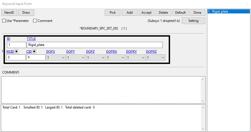
Fig: Creating Boundary Conditions
Contact :
13. Create a Contact using Keyword Manager-->All-->Control option,
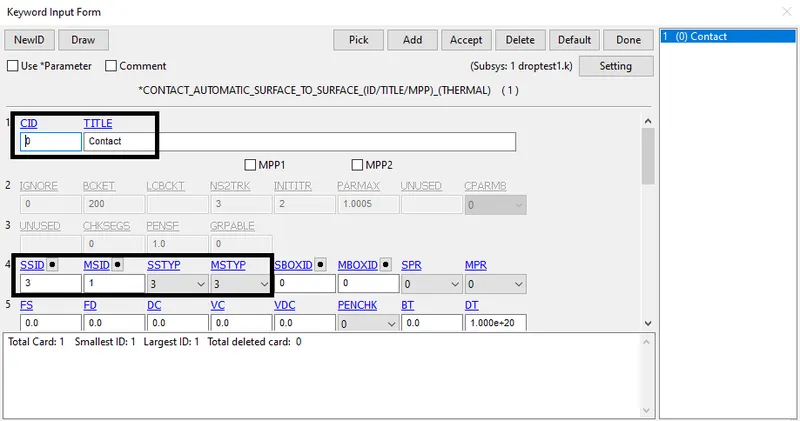
Fig: Creating a Contact for Plate & Phone
Control :
14. Create a Control card using Keyword Manager-->All-->Control-->Termination option,
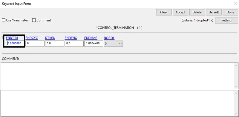
Fig: Creating Control Card
Output Requests :
15. Create an Output request to obtained plot results from the drop test simulation.
16. Go to Keyword Manager-->All-->Database-->Binary_D3Plot option and set the time step(Dt),
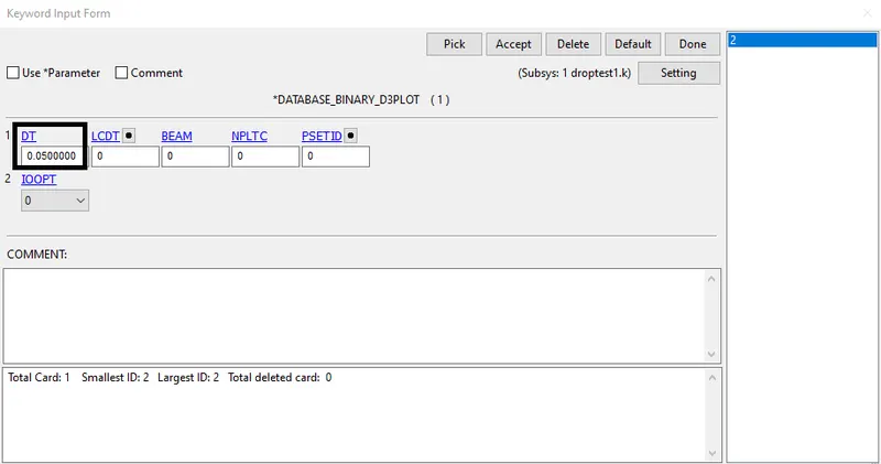
Fig: Time Step for getting output Plot results
17. Go to Keyword Manager-->All-->Database-->ASCII_option and Select GLSTAT option and set Dt value to get Energy plot results,
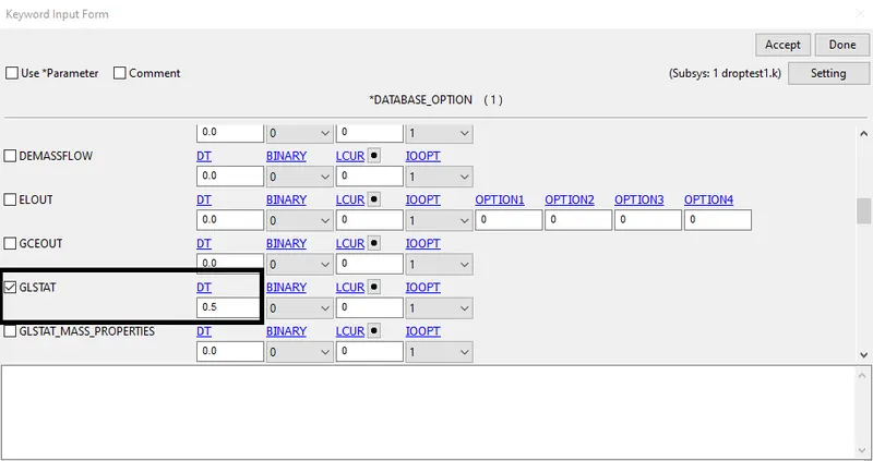
Fig: Time Step for getting Energy Plot results
Model Check :
18. Finally, Check the Model for Errors and Warnings using Keyword Manager-->Model Check option,
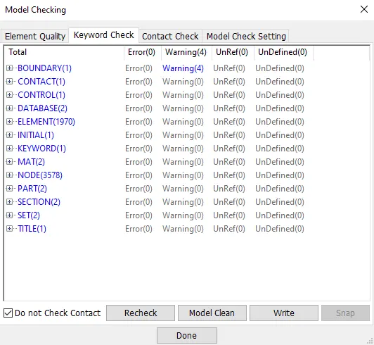
Fig: Model Checking
19. After Model Checking, Run the Simulation using File-->Run LS-DYNA option,
20. In the LS-RUN window, import the keyword file and Run the simulation.
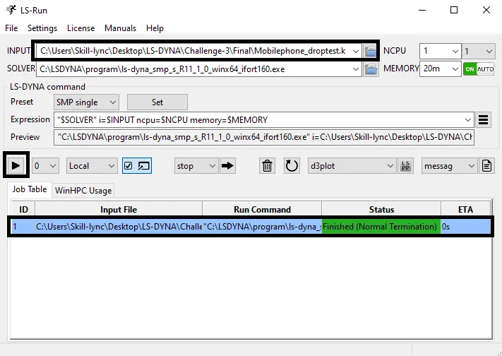
Fig: LS-Run Window
OUTPUT RESULTS :
21. Finally Simulation finished by Normal Termination and Output results has been displayed below,
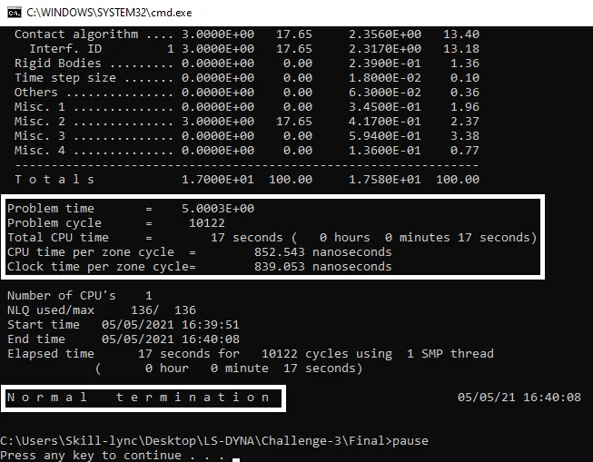
Fig: Output Result
Von mises Stress Plot :
22. Open the Binary file using File-->Open-->LS-DYNA Binary Plot option,
23. Go to Post-->FriComp-->Vonmises Stress option to get maximum stress plot.
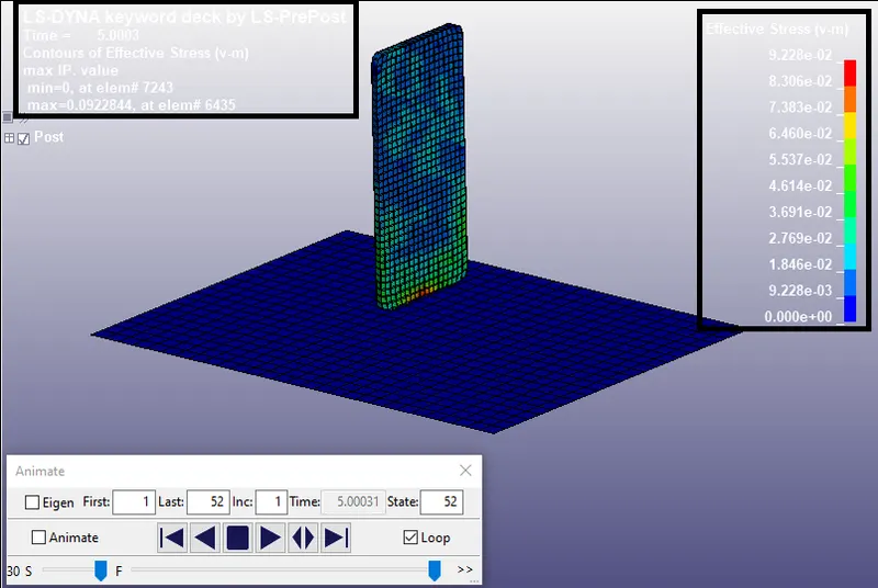
Fig: Vonmises Stress Plot
24. From the above contour plot obtained that, Maximum Stress is 9.228e-02 at the time of 5.0003 sec
Energy Plot :
25. To get Energy Plot, Go to Post-->ASCII option and load glstat, and display the energy plots.
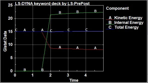
Fig: Energy Plot
CONCLUSION :
Mobile Phone Drop test Simulation is Completed by using required Input Parameters and obtained the Output results such as Vonmises Stress & Energy Plot results.