Week 3 Challenge : CFD meshing on Turbocharger
Aim: For the given model of a turbocharger, check for the geometrical errors to make appropriate volumes. Create and assign PIDs
accordingly. Create surface mesh and use that to create a volumetric mesh.
Given:
a. Blade stage-1 = 1 mm
b. Blade stage-2 = 1 mm
c. Impeller = 2 mm
d. Shaft rotor = 1 mm
e. Turbo casing = 5 mm
f. Compressor casing = 5 mm
g. Inlet casing cover = 5 mm
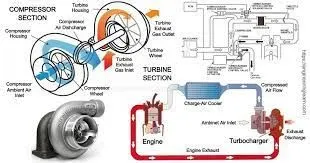
Turbocharger -A turbocharger is a device fitted to a vehicle’s engine that is designed to improve the overall efficiency and increase performance.
A turbo is made up of two halves joined together by a shaft. On one side, hot exhaust gasses spin the turbine that is connected to another turbine which sucks air in and compresses it into the engine. This compression is what gives the engine the extra power and efficiency because as more air can go in the combustion chamber, more fuel can be added for more power.
Objective-
- 2D and 3D meshing on turbocharger.
- Exploring 2D nad 3D ansa tools.
- Geomerty clean up like removing single cons, adding surfaces and removing useless surfaces.
- step by step explaination of compete process.
Procedure-
Step:1 Topological Clean up of the Model
- Import CAD model in ANSA. (Open ANSA ⇒File ⇒ Select appropriate CAD Model)
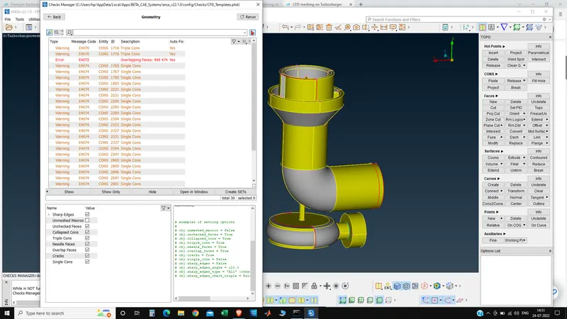
- To check for Geometrical checks errors like single Cons, Double cons and Surface overlaps.
- For Checking geometrical errors. (Tools ⇒checks⇒Geometric⇒Select single cons, triple cons, etc and then execute)
4.Clear error using Modules like Faces (Cut, Delete, Topo, Intersect), Hot Points (Insert, Project, Multi-project), Cons(Fill Hole, Release), and Auxiliaries(Fine).
5.Topo option is used to convert single cons into double cons by combining two single cons.
6.Release option is the opposite function of Topo which is used to convert double cons into single con.
7.Intersect option is used to intersect two faces.
While doing Topological clean up, try to make as a single geometry which is effective in Volumentric mesh.
Original Geometry-
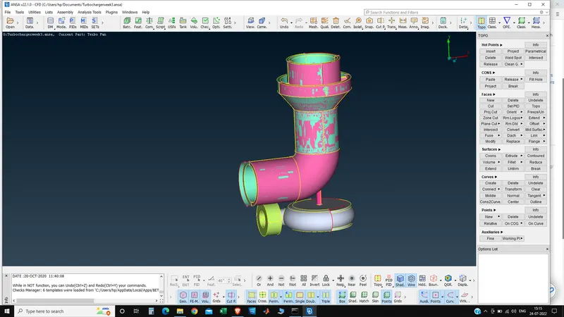
After uploading geometry into ANSA , set geomerty to PID mode. This is our original geometry , as we can observe there are mixed green and pink colors on surface, these are overlapped surface. our geometry is filled with overlapped , intersecting and extended surfaces, all these surface requires to be removed by deleting them. There are multiple single cons present in geometry and some unnescessary double cons.
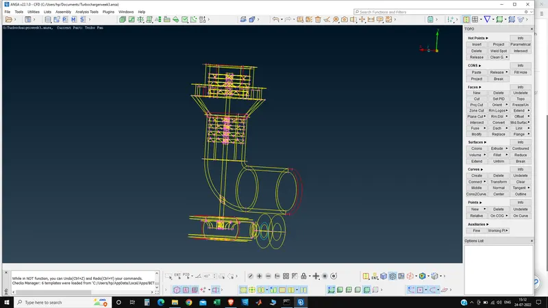
After putting geometry into wire frame mode we can see our single , double and triple cons clearly. All single cons are due to extended , intersecting or absent surfaces. All of them requires to be fixed.
after removing the extra surfaces we get the following
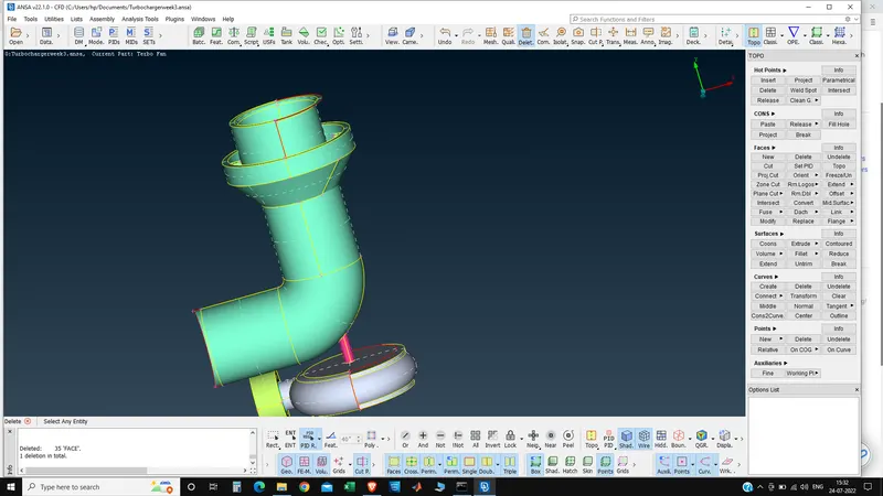
One extra surface is removed and a new surface is made -
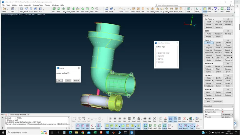
In case of turbo casing also we will create hot points and then try to join them using face tool 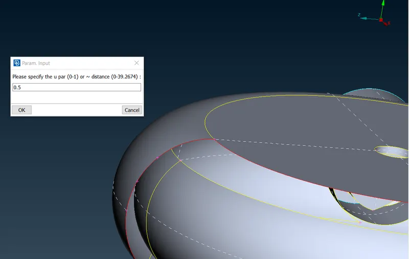
Hot points created:
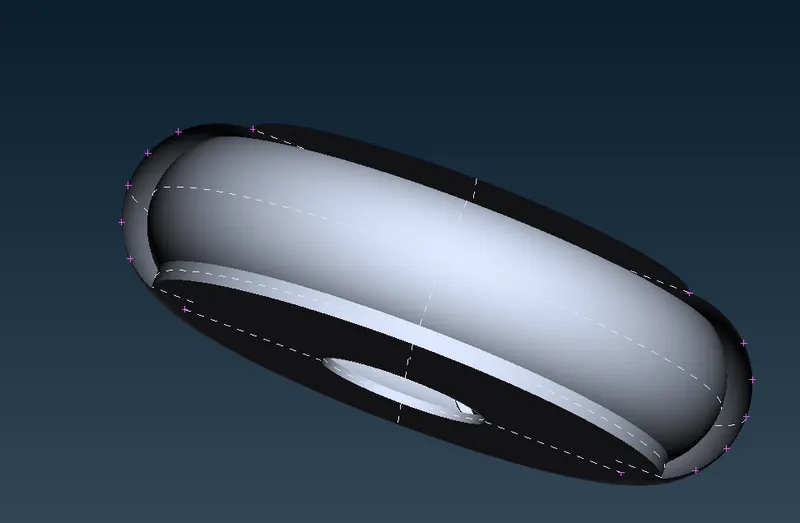
Using face tool to create new surface:
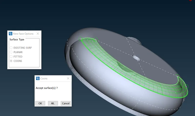
New surface created:
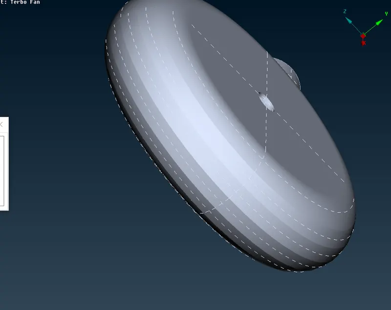
- In this case we need to use intersection tool as the two faces are intersecting each another
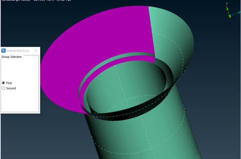
Intersection option will itself show the option to delete the exceeding surface.
Assinging relevant PID's:
Click on Surfaces > Set PID > click on surface that you want to assign a PID and also make sure that wire option is enabled
Left click on surface to select it and click middle mouse button to assign a new PID to your selected surface
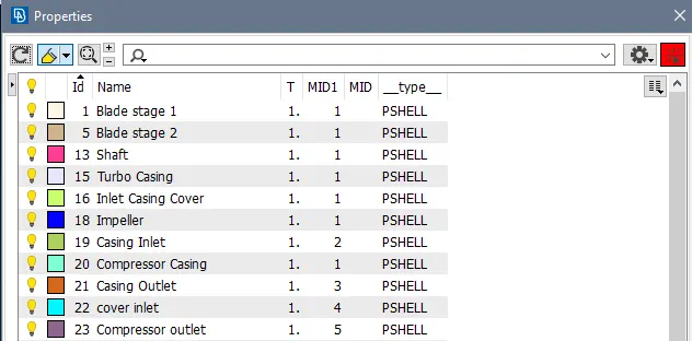
Repeat the same process to assign PID's for remaining surfaces
Surface Meshing:
Select the MESH module button > parameters > length
Drag the cursor to cover the entire model and click middle mouse butto to give the mesh size as 5mm for entire model
Select Mesh generators > Free mesh and drag the cursor to cover the entire model and click middle mouse button
The entire model is meshed with size of 5mm
Similarly Meshing of individual components is done according to th given requirements
Blade stage1 = 1mm
Blade stage2 = 1mm
Impeller = 2mm
Turbocasing = 5mm
Compressor casing = 5mm
Shaft = 1mm
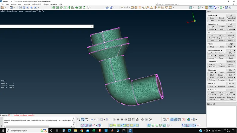
After meshing the turbo casing with the 5 mm length we obtain the following -
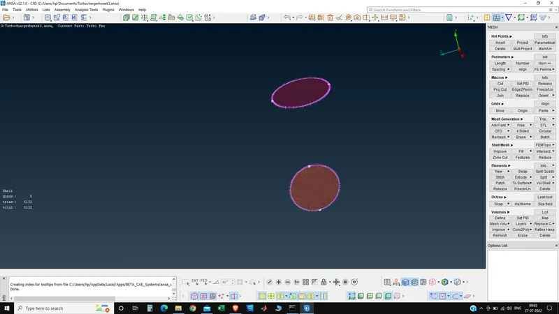
The inlet and the outlet casing are given element length = 1 mm the thing that is obtained as -
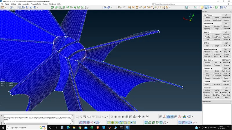
Next the Impeller blades is meshed by the element side is of 2 mm -
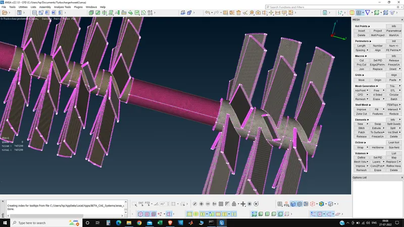
Next the two compressor blades are meshed using the length of 1 mm in the PIDS are named as blade stage1 and blade stage2-
The final surface mesh is-
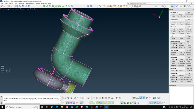
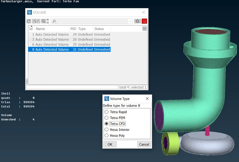
Now we are going to do volume mesh by clicking on to the each and individual volumes and then go to remesh and do tetra CFD- The tetra CFD meansw the element size is of tetrahedral and the application of the element is of the CFD.
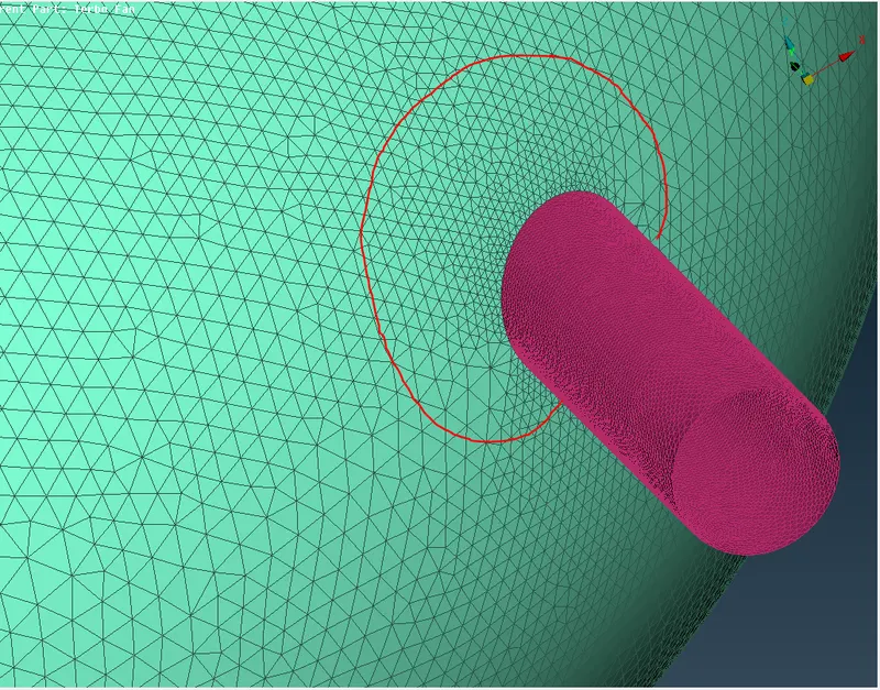
NOTE: While meshing you will come across a problem which is disappearence of meshes from regions where 2 PID's with different mesh length are joining. This happens because of mesh size domination as ANSA is confused which mesh size to follow at transition points between two PID's.
To cope with this problem
- while giving macros length you will see mesh length varying in a range in which minimum length will be of one PID and maximum length will be of PID on which youn are meshing. So dont give any input in macros and select spot mesh option to mesh.
- In below picture we can observe mesh size of green color PID is changing as it approached pink color PID. This is adjusting mesh size at joining point of PID's with different mesh length.
VOLUMETRIC MESHING
Volumetric mesh can be done only after 2D meshing . To check how many surface are available for volumetric meshing choose define option from volumes and then wholebd and click ok.
This step will show PID's available for volumetric meshing. In our case we got 8 PID's.
To check which PID's to keep and which to delete
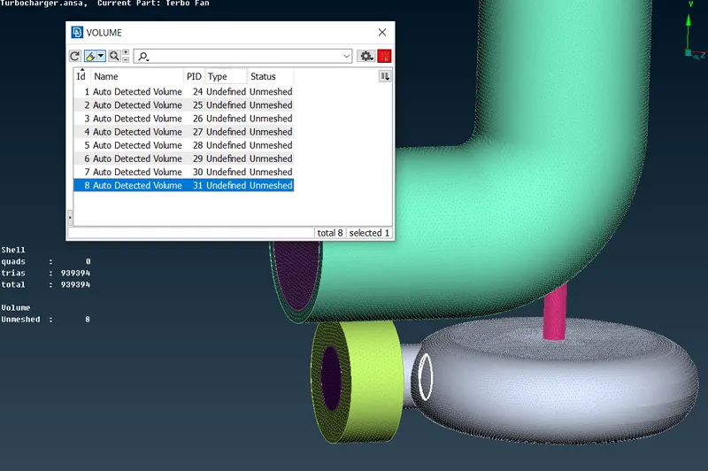
- PID's which represents thickness of geometry are required to be deleted.
- PID's which represents volumes inside of geometry are required to be kept and these will be meshed.
PID to be deleted:
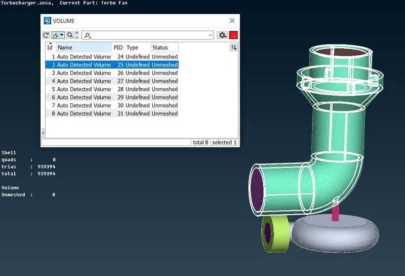
PID to be deleted:
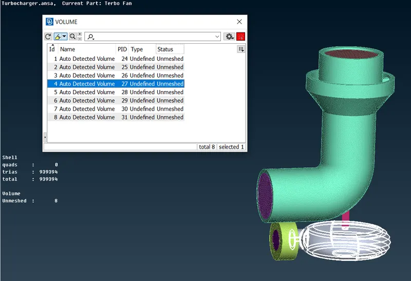
PID to be deleted:
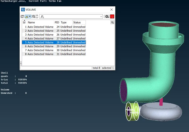
PID to be deleted:
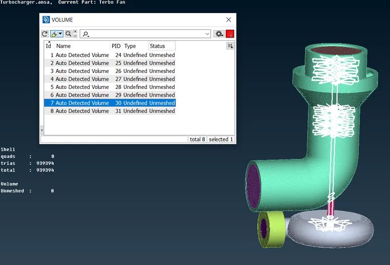
Volumes to keep-
PID to keep:
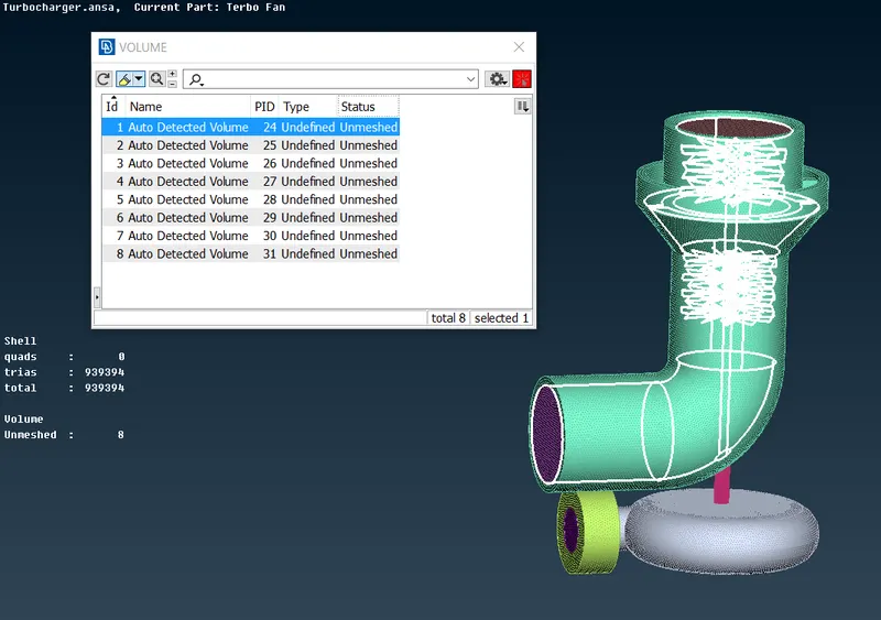
PID to keep:
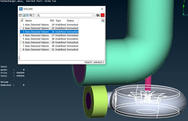
PID to keep:
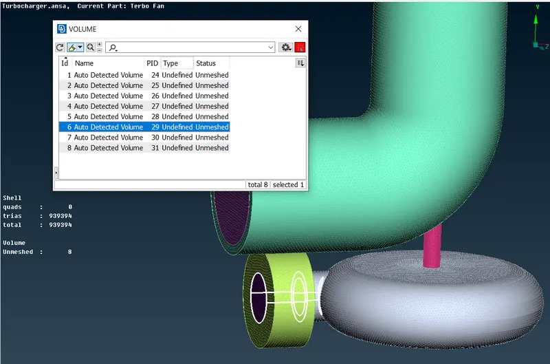
PID to keep:
Steps to do volumetric mesh:
- Do right click on PID name and choose remesh option from drop box.
- After clicking on remesh a pop-up-box will appear which will contain ifferent type of meshing techniques. Choose tetra CFD as we are doing CFD operation.
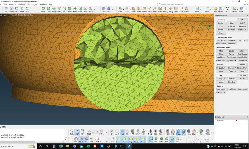
The final volume mesh is -
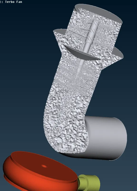
Conclusions:
1. Achieved volumetric mesh of the turbocharger model.
2. Different mesh length sizes tend to give errors at the contact regions of 2 different mesh length regions, therefore mesh ranges can
be given to avoid erasing of mesh.
3. Volumetric mesh can be achieved only after creating surface mesh successfully, or else the geometry can give fatal errors while
volume meshing.
4. Overlapped surfaces can be deleted using the universal delete option.