Week 3 Challenge : CFD meshing on Turbocharger
Objective:
For the given model, check for the geometrical errors to make appropriate volumes. Create and assign PIDs as shown in the video. Perform surface mesh with the given target lengths as per PIDs.
- Blade stage-1 = 1 mm
- Blade stage-2 = 1 mm
- Impeller = 2 mm
- Shaft rotor = 1 mm
- Turbo casing = 5 mm
- Compressor casing = 5 mm
Inlet casing cover = 5 mm
AIM:
we have learned about volumetric meshing. Now in this challenge, the main purpose is: Topo cleanup >> surface meshing >> control volume extraction >> volumetric meshing.
Steps on ANSA:
1. 1. Importing the geometry into ANSA and checking for pids for topo cleanup.
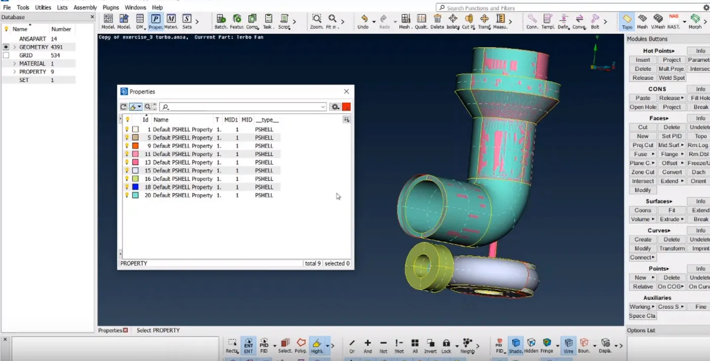
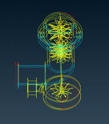
We need to find out the correct cross edges of surfaces that are not required here and then delete them.
1. Will do first topo cleanup on a very raw model. We can notice here that so many surfaces are missing and also we can check the geometry from check window
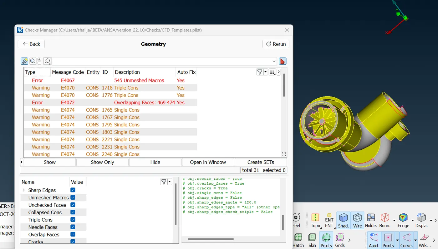
we can see that there are so many errors here. one by one we will solve the error by isolating each element of turbocharger using !Not option under PID mode.
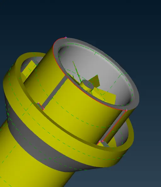
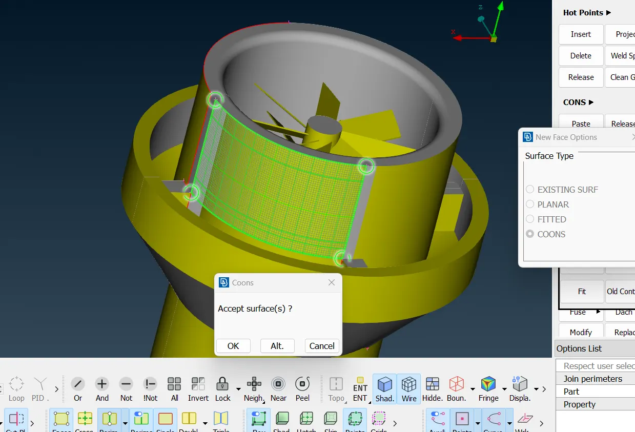
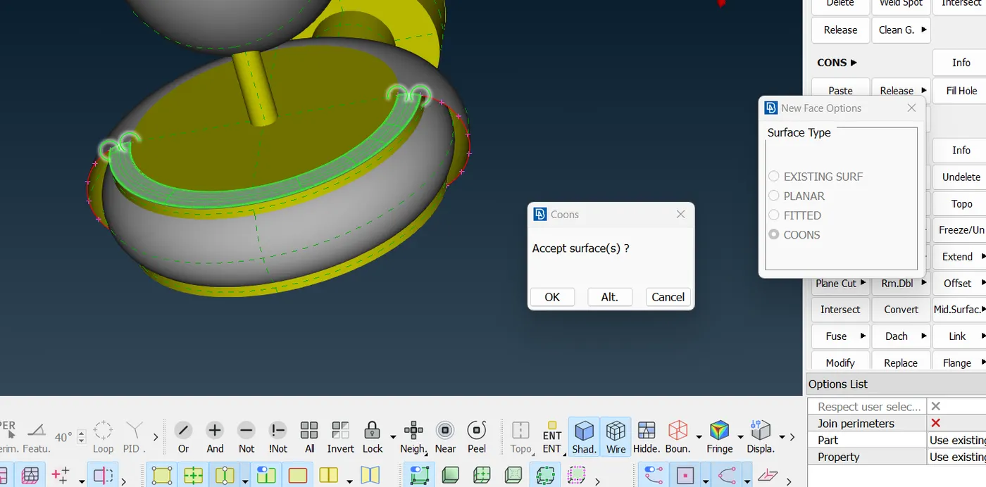
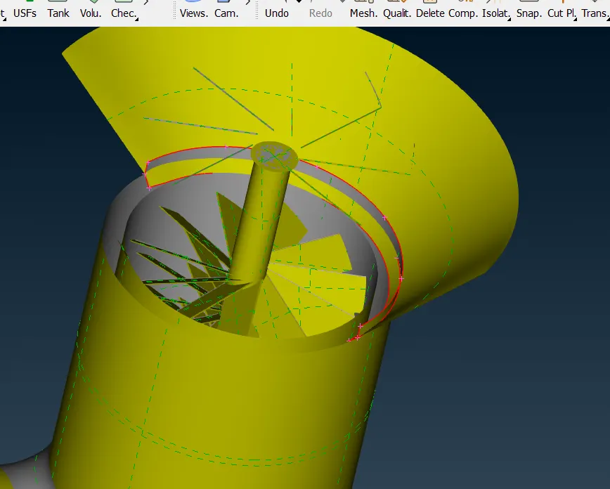
most of the critical errors are solved by understanding that when we need to insert the hot points and when we have to delete them. Some of them are solved by releasing triple cons and identify which neighbouring face doest have that single con to project the single cons. After than cut option along the con is applied to seperate the glitches of triple con errors.
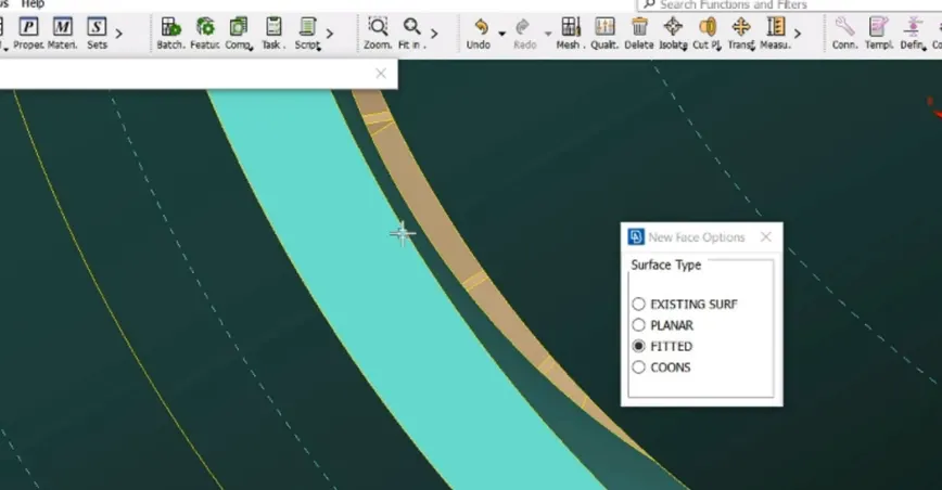
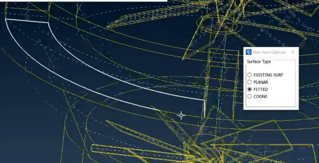
using new face creation command we can solve single cons problems
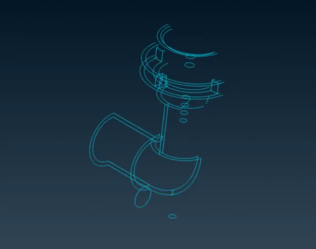
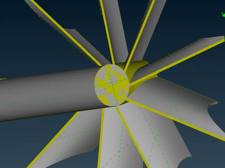
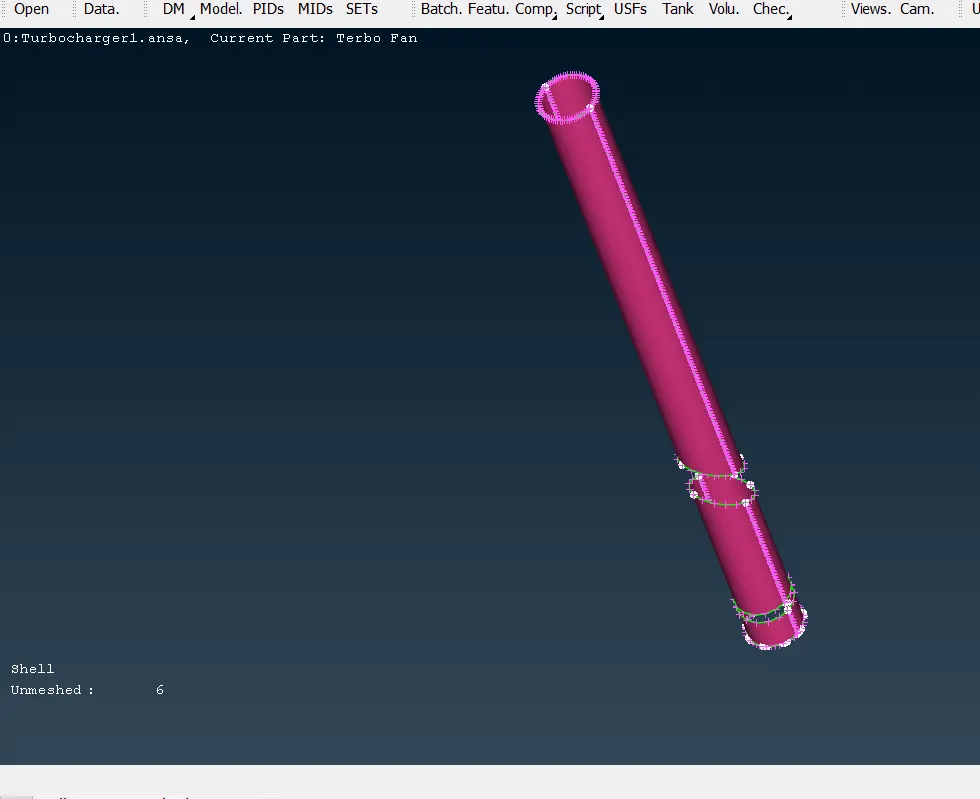
There are some critical errors in delicate surfaces of blades and shaft.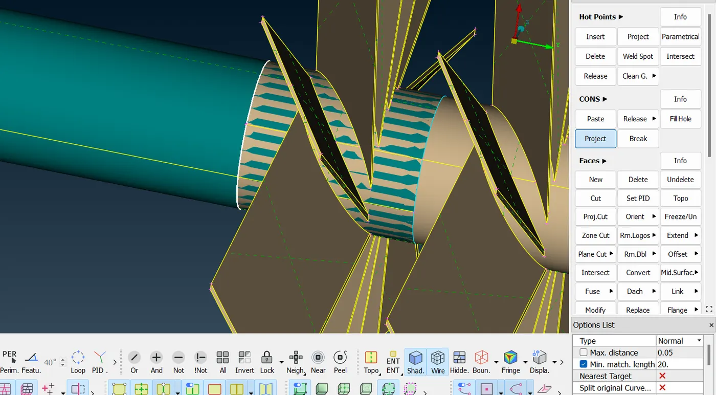
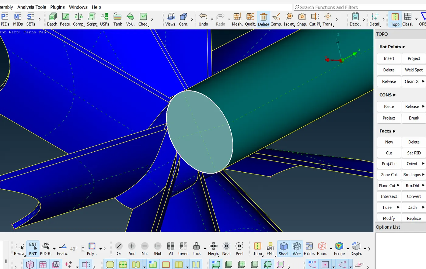
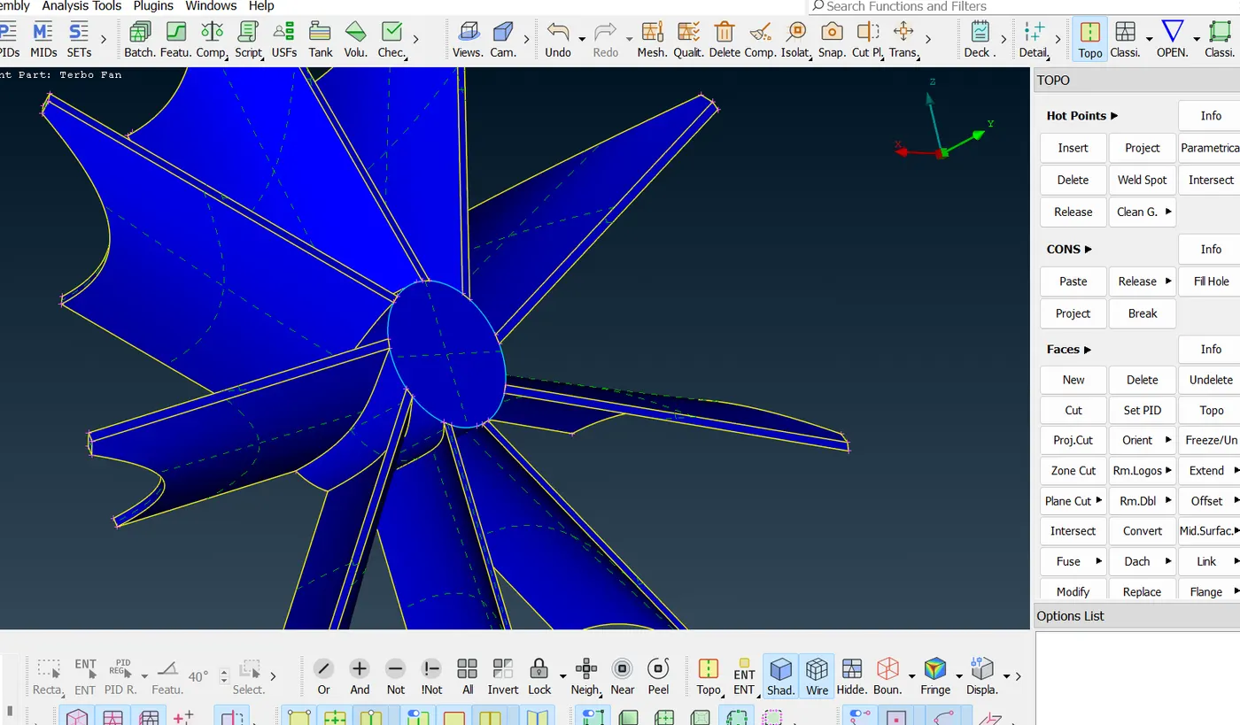
by using cut option we can seperate the glitching surfaces here and delete the extra faces not needed
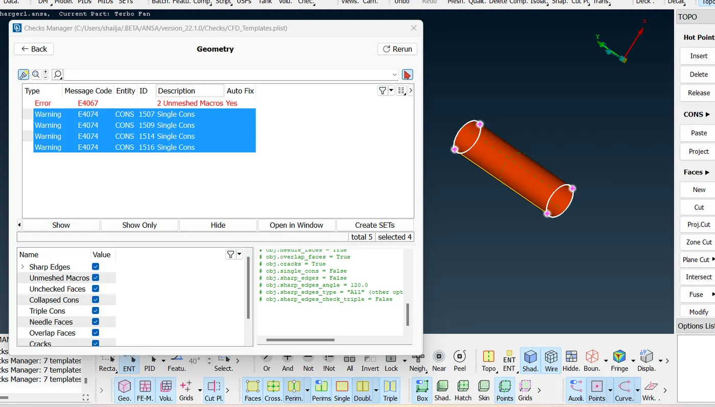
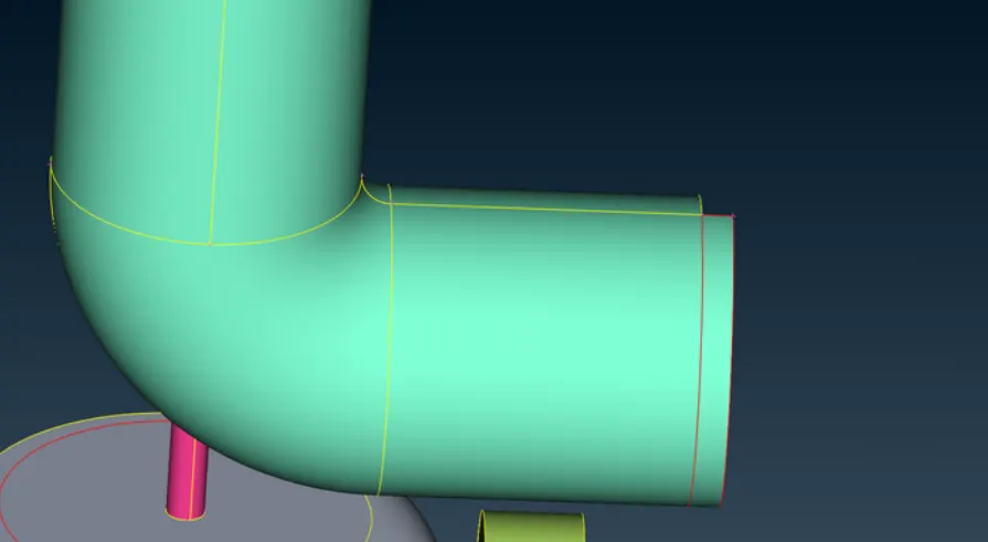
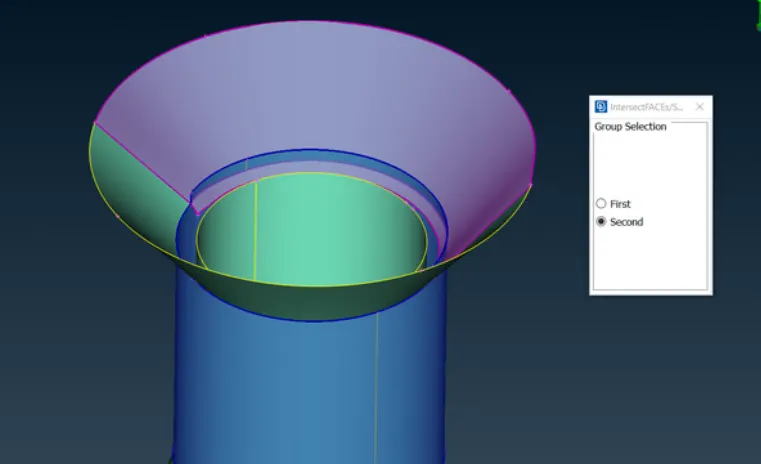
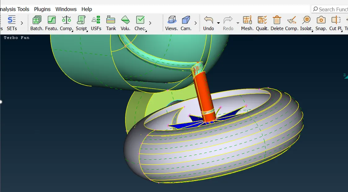
For solving the intersecting faces single edges error, we use the intersect face tool to trim the extra surface. We chose the first and second face as shown above.
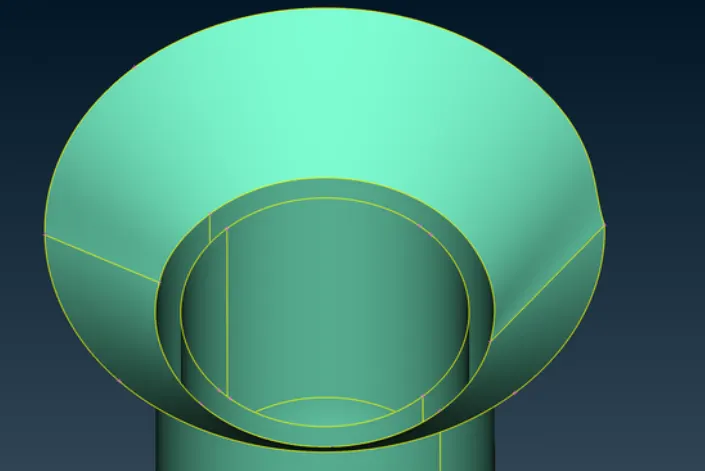
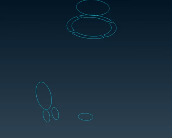
now we have only these triple cons that are actually required to join 3 faces not as an error
Step 2:
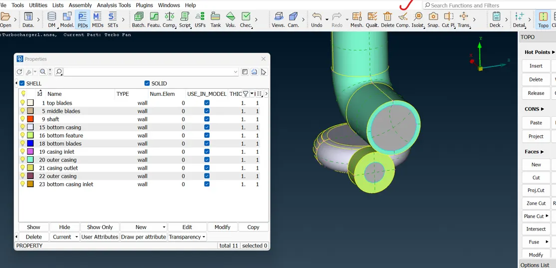
PIDs naming and new PIDs creation and applying them to their dedicated elements of turbocharger
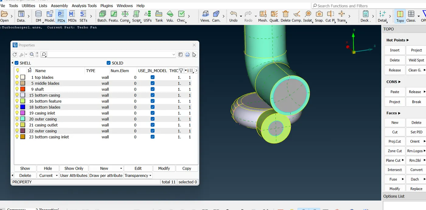
step 3: starting with surface meshing
Performing surface mesh with the given target lengths as per PIDs.
- Blade stage-1 = 1 mm
- Blade stage-2 = 1 mm
- Impeller = 2 mm
- Shaft rotor = 1 mm
- Turbo casing = 5 mm
- Compressor casing = 5 mm
- Inlet casing cover = 5 mm
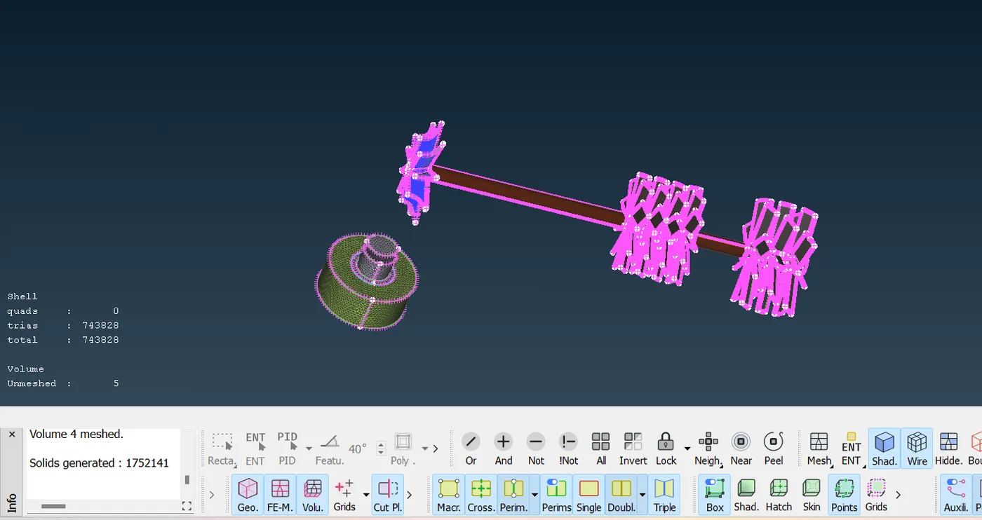
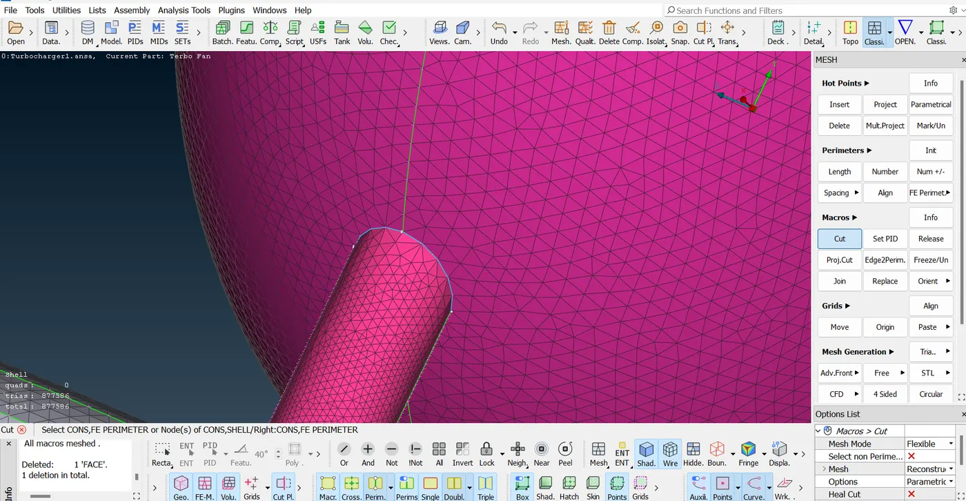
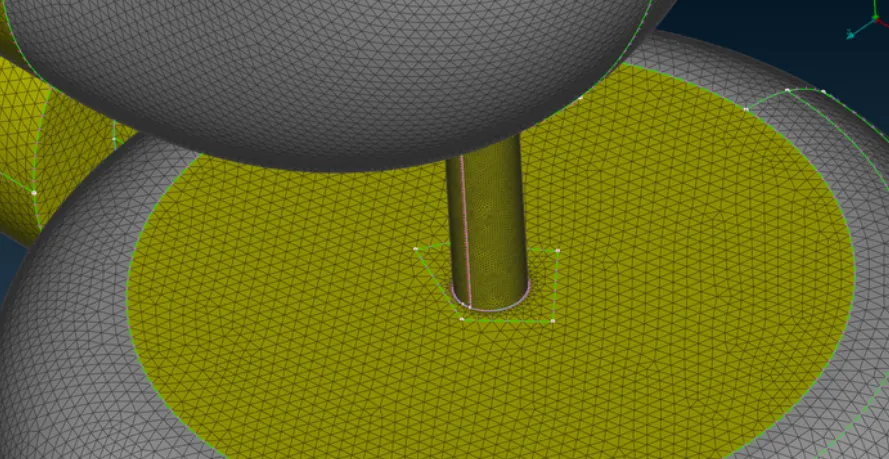
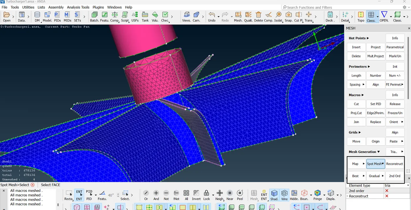
while meshing we will get some challenges where the impeller is joining shaft, between body casing and shaft, lower casing and shaft, blades and shaft. this happens because of different meshed sizes of neighbouring PIDs. we need to define the perimeters of PIDs and need not o assign length size to them. directly we can apply macro mesh length and spot meshing. As we define a range of mesh length like min target length. we can solve this issue by ranging the mesh length of shorter mesh length PID in domain of larger mesh length PID.
release(converts 1 triple coons into 2 double coons and 1 double coons into 2 single coons) and topo(2 double coons into 1 triple coon and 2 single coons into 1double coon) are opposite in work
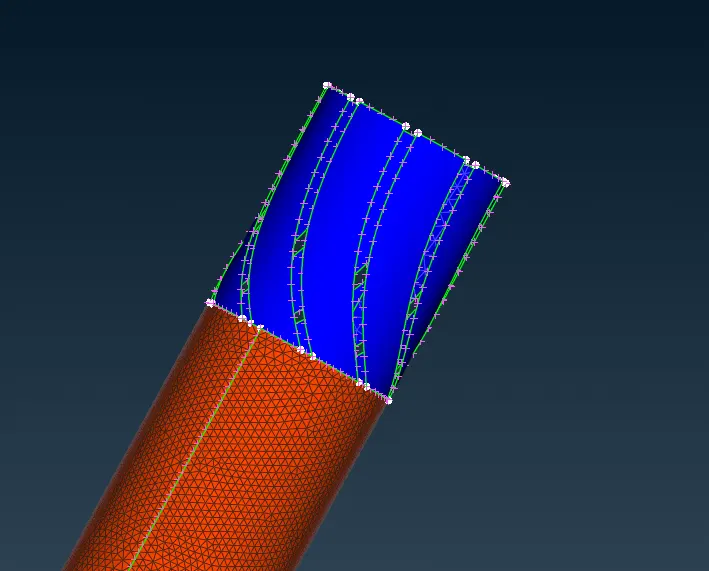
above issue can be solved by ranging the mesh range 0.5mm to 1.5mm to blade shaft as mesh length of shaft is 1mm and 2mm for impeller blades range 1 to 3.
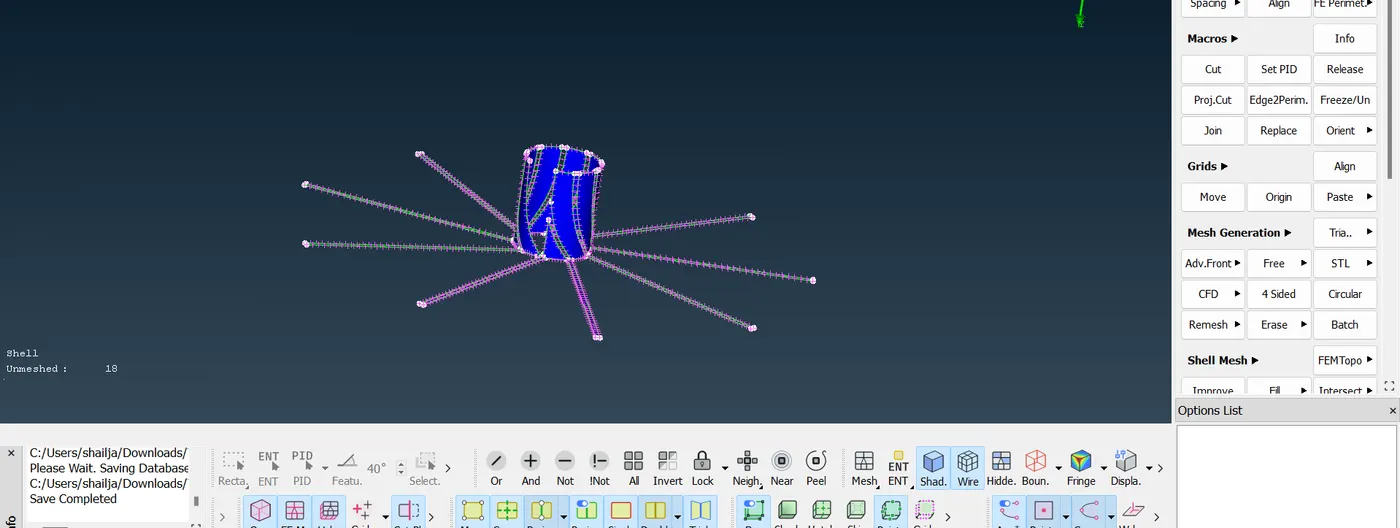
step 4: now moving to volumetric meshing
Now will volumetric meshing n for this we need to check geometry is closed means no hole errors or extra surface or cons
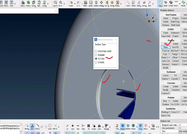
this the open faces here in casing and inner elements of turbocharger and we need to close them
1. redefining the PIDs:
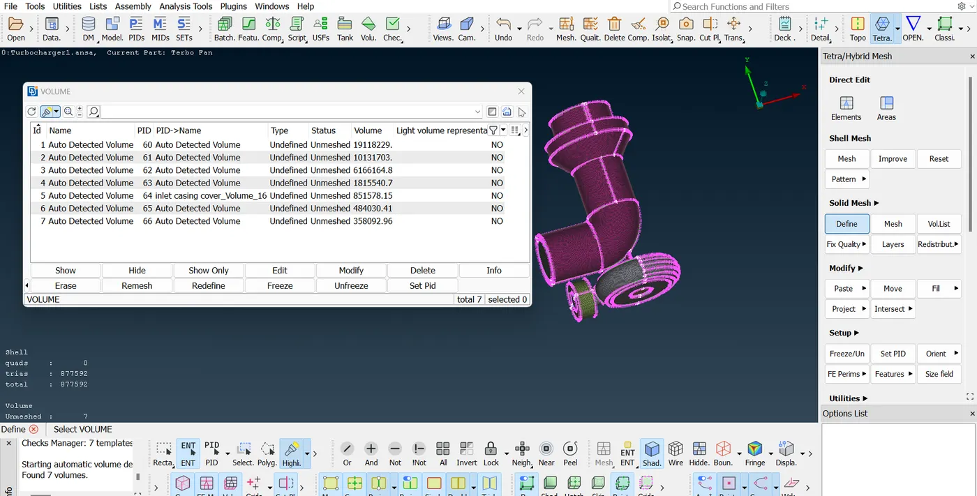
by default ansa has detected 7 volumes ie closed geometries
We have to take care of which volumes are needed means fluid will flow through that and which are not needed. It means the volume must have some thickness
we will keep 3 volumes only and delete others as they are material(parent geometry) ie thickness vol not flow volume
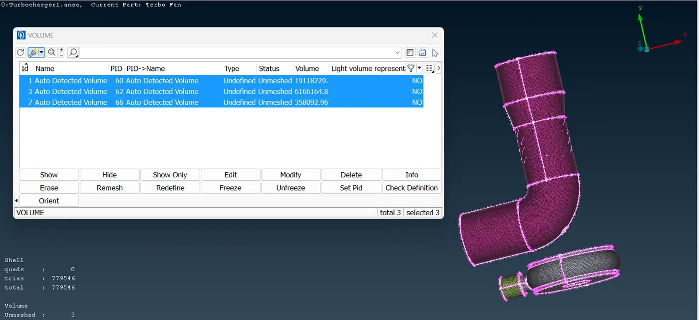
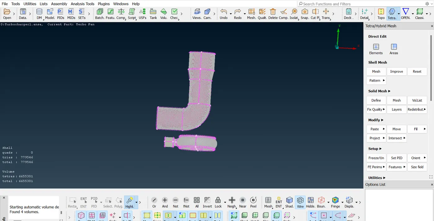
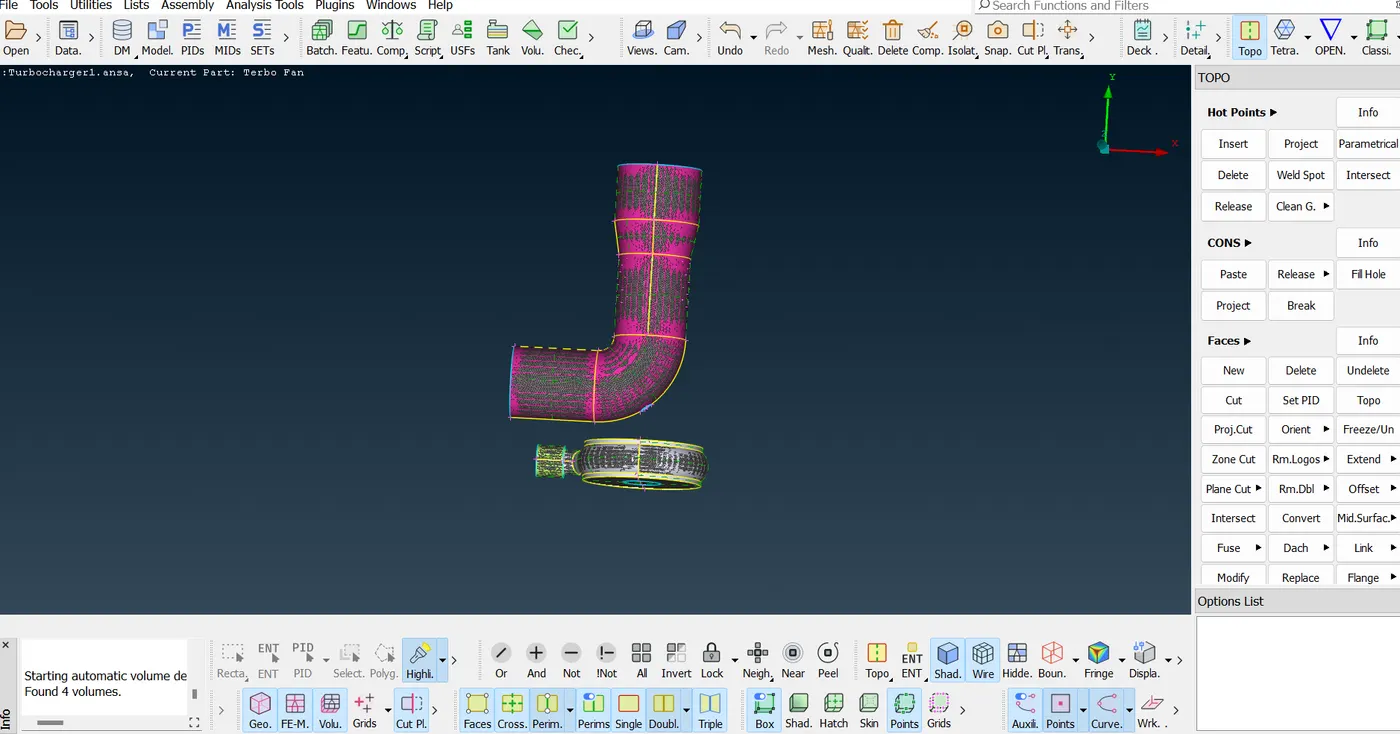
we can see some glitches as geometry and
geometry volume were turned on.. turn them off
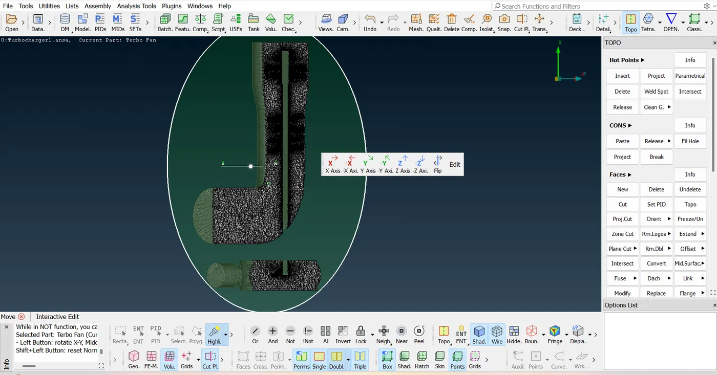
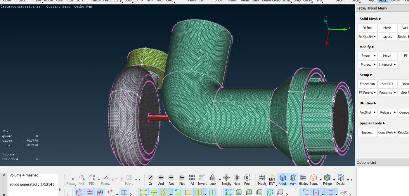
After volume meshing is completed, we see the following mesh. From the cut section view of the mesh, we can see the variation of the cell size (1-2mm to 5mm) from the blades of the compressor/turbine and shaft rod as we move away from them.
Conclusions:
1. The errors like single, double and triple cons are checked and resolved
2. PIDs are assigned to different parts of geometry
3. surfaces are generated with the given target mesh lengths. Then volumetric meshing is performed for the volumed required successfully.