Week 3 Challenge : CFD meshing on Turbocharger
CFD Meshing on Turbo Charger
Aim:
For the given Turbo charger model, check for the geometrical errors to make appropriate volumes. Create and assign PIDs. Perform surface mesh with the given target lengths as per PIDs.
- Blade stage-1 = 1 mm
- Blade stage-2 = 1 mm
- Impeller = 2 mm
- Shaft rotor = 1 mm
- Turbo casing = 5 mm
- Compressor casing = 5 mm
- Inlet casing cover = 5 mm
Perform Volumetric mesh for the required volumes.
Turbo Charger:
A turbocharger, often simply referred to as a "turbo," is a device that forces more air into the combustion chamber of an internal combustion engine. This additional air allows the engine to burn more fuel, which results in increased power output. Turbochargers are commonly used in both automotive and industrial applications to improve the efficiency and performance of engines.
The operation of a turbocharger involves a continuous cycle: the exhaust gases spin the turbine, which is connected to the shaft, and the shaft, in turn, spins the compressor wheel. This compressed air is then forced into the engine's combustion chamber, allowing for improved combustion and increased power output.
Turbochargers are widely used in the automotive industry, particularly in performance and diesel engines, as well as in various industrial applications where increased power and efficiency are essential.
Surface Meshing:
Import Geometry : Load the Turbo Charger model into ANSA.
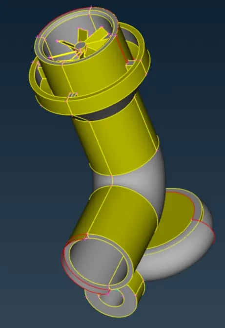
Check for Geometrical Errors:
- Inspect the geometry for any errors using ANSA's built-in geometry checking tools.
Check à Geometry à Select Visible à Check all the options except Unmeshed Macros à Execute
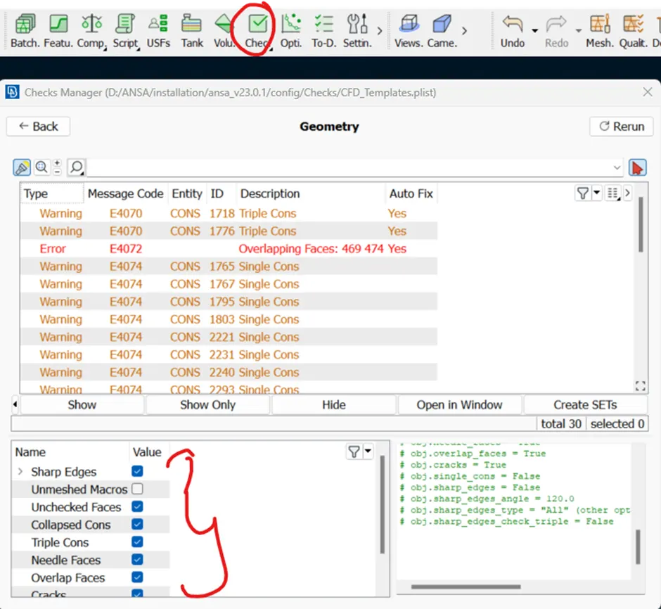
- Correct all the issues to ensure a clean and error-free geometry.
- Use the following options and turn on wireframe mode to check single and triple conns.

- Check all the single conns and create the surface if missing or connect with existing geometry to resolve the issue.
- Triple conns might be present due to overlapping surfaces or duplicate geometry. So check all the triple conns and delete overlapping surfaces if present.
- Zoom in and visually inspect the areas with triple conns. Look for overlaps, redundant geometry or areas where surfaces may not be properly connected.
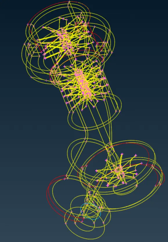
- Once the geometrical errors are fixed, close all the openings for the volume Mesh.
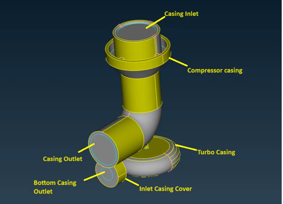
- Finally the geometry looks as given below.
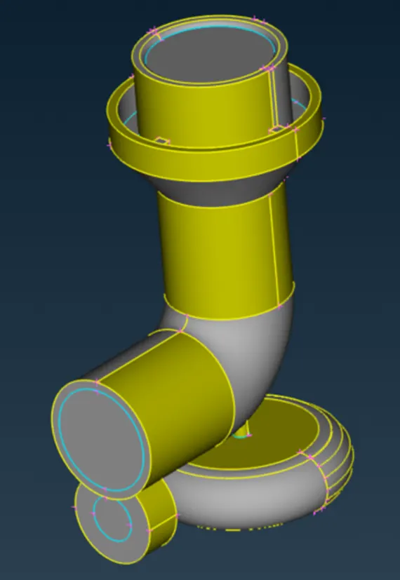
Create and Assign PIDs:
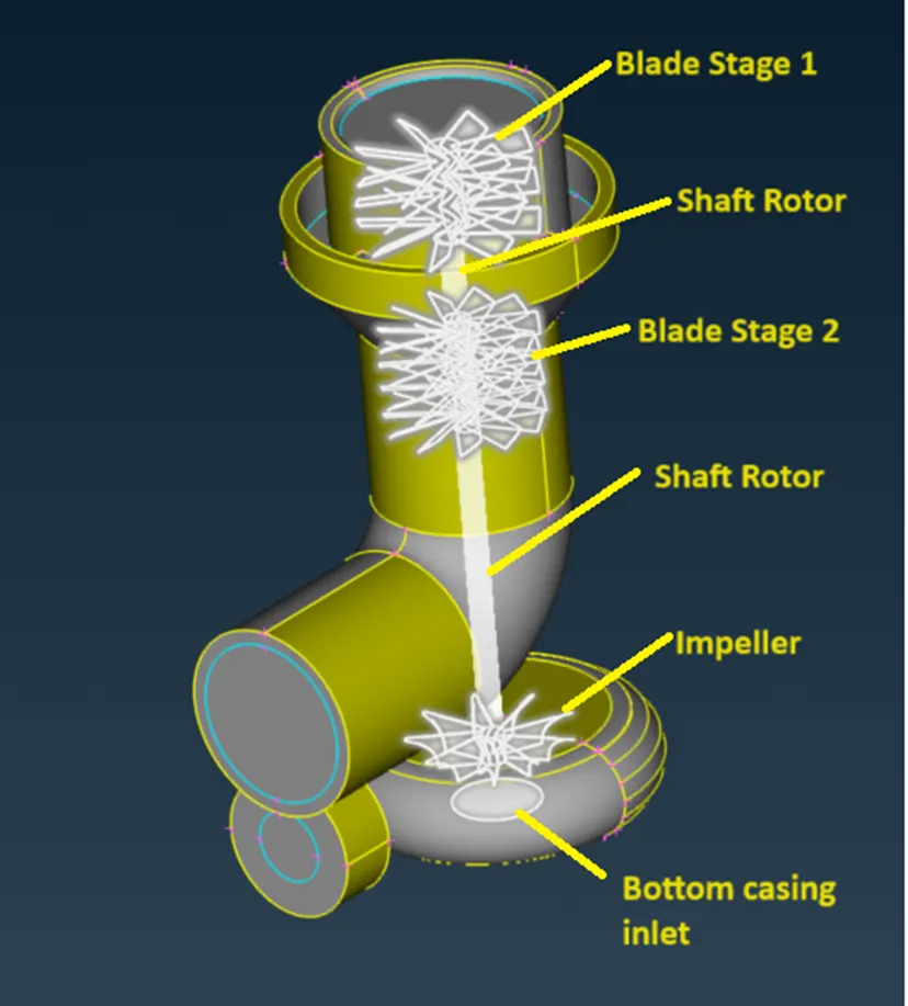
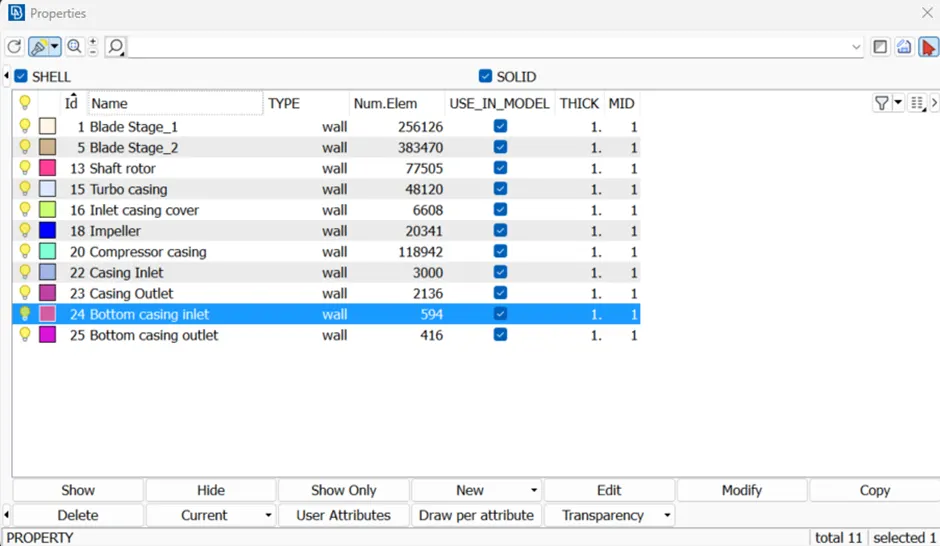
- Define Property IDs (PIDs) for each component (Blade stage-1, Blade stage-2, Impeller, Shaft rotor, Turbo casing, Compressor casing, Inlet casing cover).
- Assign these PIDs to the corresponding geometry entities.
Surface Meshing with Target Lengths:
Set target lengths based on the given specifications
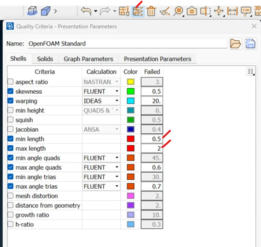
Blade stage-1 = 1 mm, Min. Length = 0.5, Max. Length = 2
Blade stage-2 = 1 mm, Min. Length = 0.5, Max. Length = 2
Impeller = 2 mm, Min. Length = 1, Max. Length = 3
Shaft rotor = 1 mm, Min. Length = 0.5, Max. Length = 2
Turbo casing = 5 mm, Min. Length = 3, Max. Length = 7
Compressor casing = 5 mm, Min. Length = 3, Max. Length = 7
Inlet casing cover = 5 mm, Min. Length = 3, Max. Length = 7
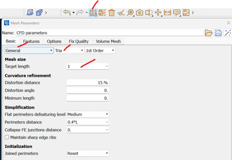
Give Target Lengths in the following options to create a proper Mesh for each component.
- Mesh Deck à Perimeters à Length à Perimeters and Macros
- Mesh Parameters
- Quality Criteria
Perimeters and macros
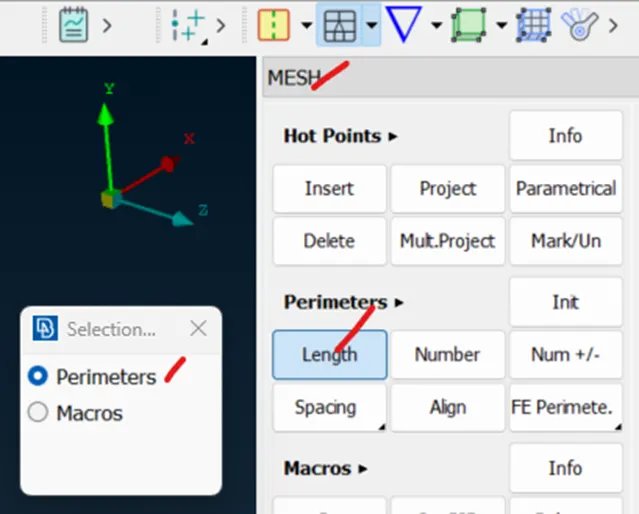
- Once the Perimeter is chosen, select the component using box selection.
- Do the same for Macros.
Mesh Parameters
Quality Criteria
After Surface Meshing
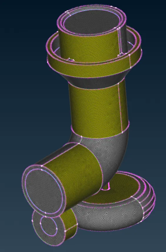
- Now inspect the generated Mesh for all the components to ensure it conforms to the geometry and target lengths. Refine the Mesh as needed to achieve the desired quality and resolution.
- Conflicts arise at the junctions where meshes of different sizes come together. In these areas, it is necessary to apply a recommended mesh length provided by ANSA to ensure proper meshing.
Volumetric Meshing
V.Mesh Deck à Define à Detect On: Whole db à ok
Ansa automatically detects the volumes to Mesh that we have created in TOPO mode.
The volumes that are highlighted below are essential as they facilitate the flow of fluid.
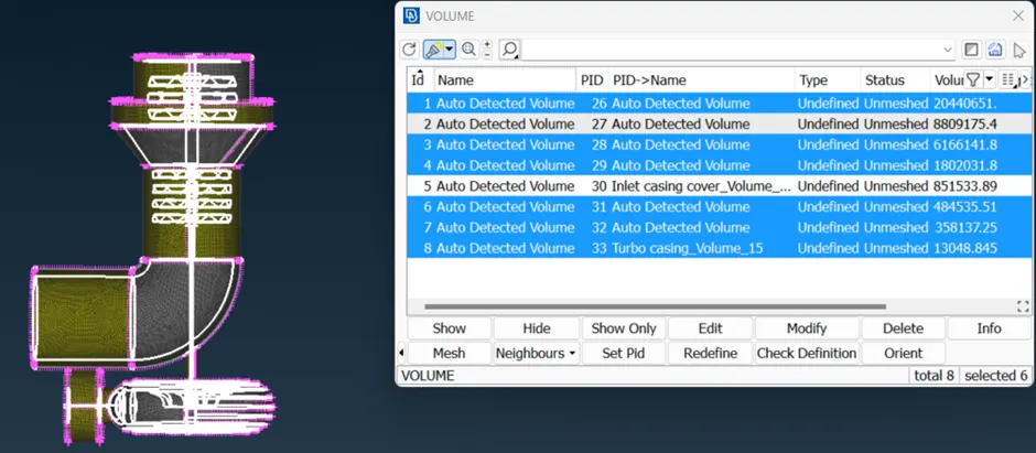
Other Volumes are not needed, as they represent the thickness of the component. So these volumes can be deleted by right clicking on it.
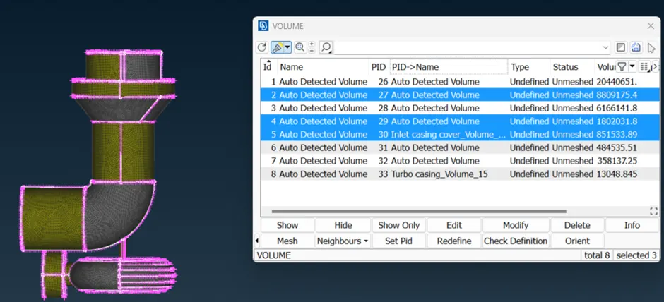
After deleting unwanted Volumes, select Tetra CFD from Unstructured Mesh then select component to Mesh and middle click. Now the status will be changed into Undefined unmeshed to Tetra CFD Meshed.

Follow the same for all the components for Volume Mesh
Afrer Volume Meshing
The mesh size gradually gets larger moving from the shaft rotor towards the outer direction. Near the blades, the mesh is smaller, and it increases as you move away. This is due to different mesh size given during surface Meshing.
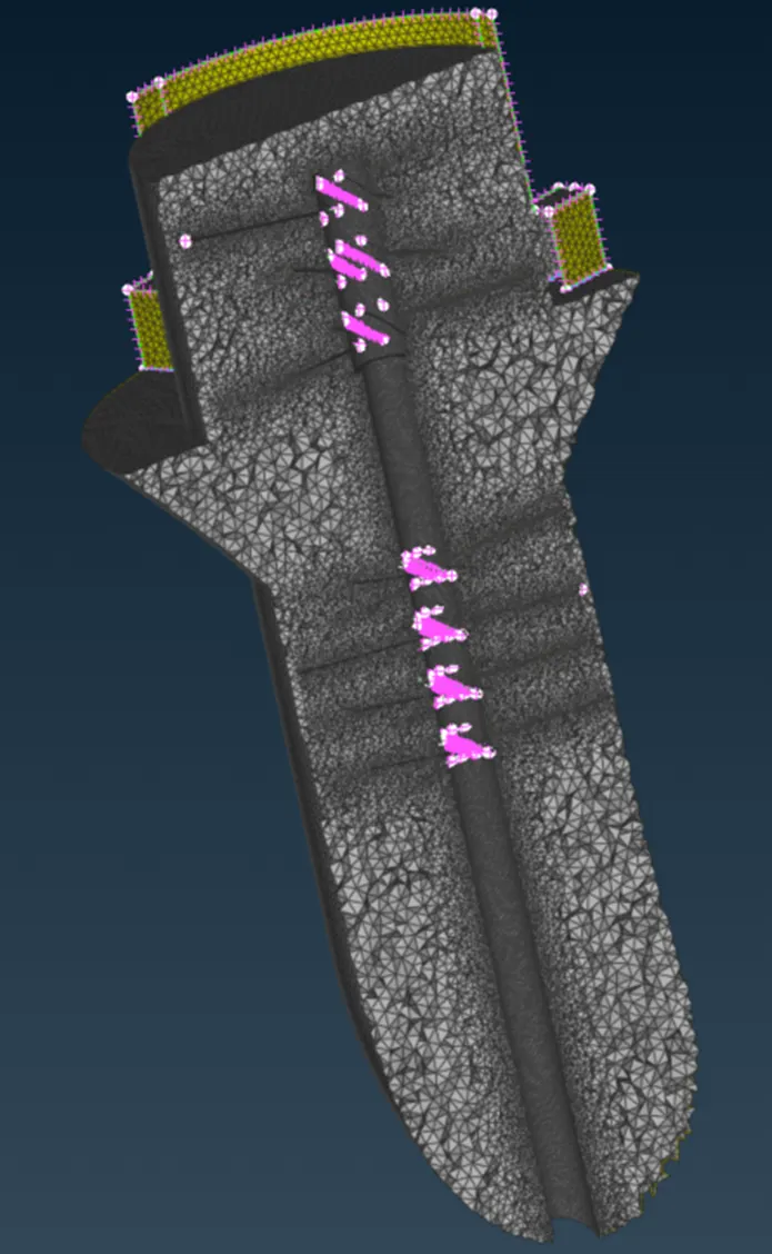
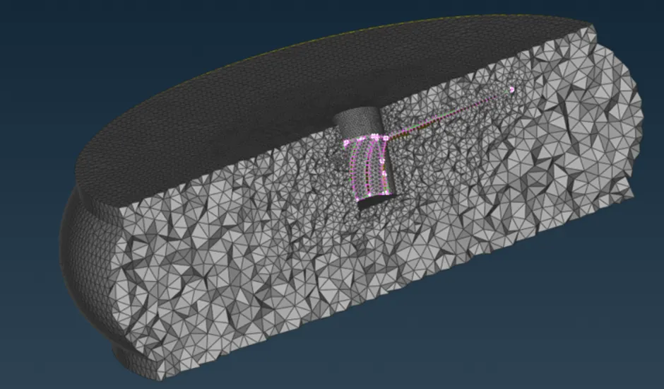
Volumetric Mesh can be achieved only after correct geometric clean-up and surface mesh.
Learning outcomes:
· From this project, we learned how to load the geometry and check for errors by looking at single and triple connections. Single connections occur when there's no link between parts, while triple connections happen due to duplicate or overlapping geometry.
· When there's both a double and single connection, we can use the Topo option to combine them into one triple connection. Conversely, using the Release option will revert it to a single and double connection.
· Triple connections occur when three surfaces meet. We visualized and analyzed the model using Boolean operations to handle single and triple connections and to create surfaces.
· We created Property IDs (PIDs) using various selection modes such as Entity, PID, and PID regions. The mesh length was determined using the perimeter options in the TOPO deck, Mesh Parameters, and Mesh Quality.
· For volumetric meshing, ANSA detected volumes, and any unnecessary volumes were deleted. We used CFD tetra for volume meshing.
Model
https://drive.google.com/file/d/1iWokFhqQZ_KU3Hj4WkDl68-uh9BGPN2t/view?usp=sharing
Conclusion:
In conclusion, we successfully examined and corrected geometrical errors, establishing suitable volumes for the specified turbocharger model. Surface meshing was conducted with designated target lengths based on Property IDs (PIDs). Additionally, we accomplished volumetric meshing for the fluid region within the turbocharger model and visualized the resulting 3D mesh. This comprehensive process ensures the model's integrity and provides a solid foundation for further analysis and simulations.