Week 3 Challenge : CFD meshing on Turbocharger
Aim: Perform topo clean-up, surface mesh, and volumetric mesh
Procedure:
- The model already has PIDs created
- There is glitching present
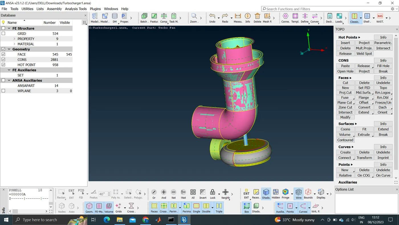
- To see all triple cons: Topo→Faces→Topo→select the model(Box selection)
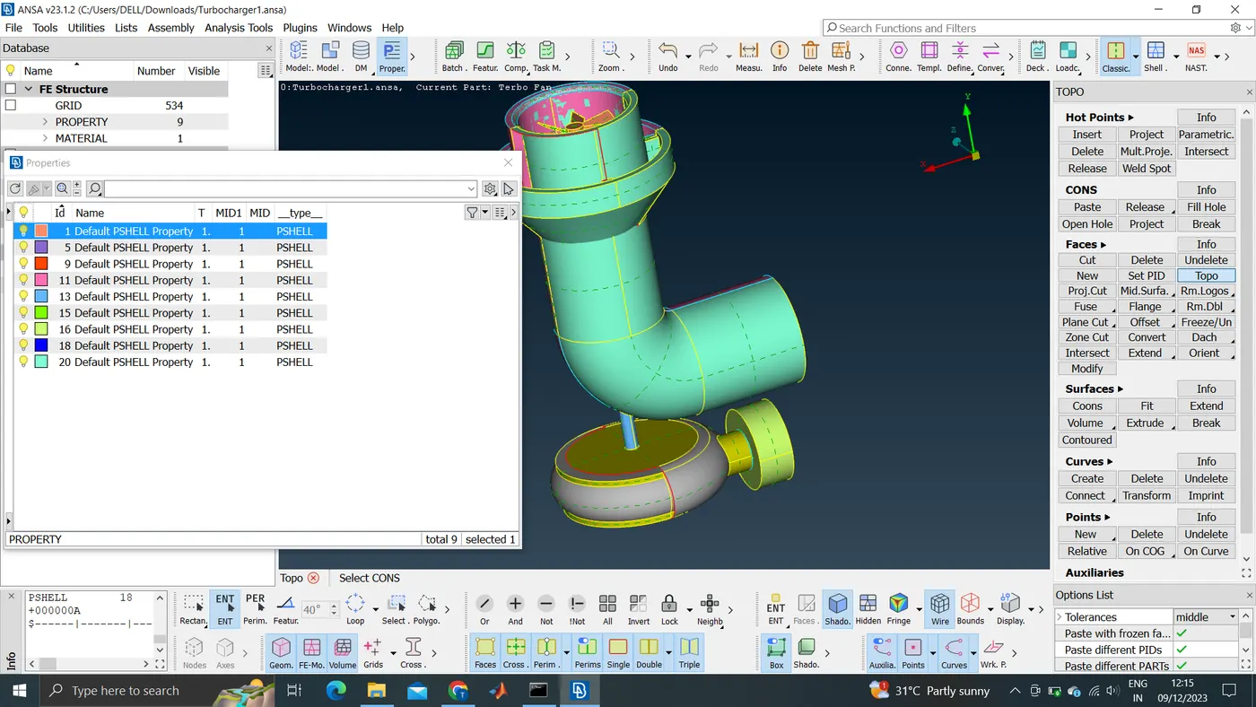
- Delete the pink surface using the PID region
- Project points and create surface using coons
- To intersect faces: Faces→Intersect
- If faces are separated and still triple cones are present, they can be released using the release option
- Release creates 3 single cons from a triple cone and 2 single cons from a double cone. And topo works the opposite
- The bottom bulged-out surface is created using multiple hot points piece by piece
- Middle click on the header of the properties toolbox is used to hide it partially
- The errors in the model are found using check→Geometry→Evaluate
- Check every triple cone using the iNot option and see if a triple cone is needed or not
- Delete the surface from the cross edges if many surfaces are present
- To cut a specific part of a PID, Project cones to that PIC is cut the desired part
- Then use the Fine option to make the cone in the desired shape
- The cut option can also be used to cut the desired part of a PID
- Two closely placed single cones can be pasted together to make a double cone using the Paste option
- Geometry must be closed to perform the volumetric option
- The bulged surface in the bottom is not closed below, it's closed by adding a new surface
- The upper top is also closed by creating a new surface
- The side structure is also closed
- After making sure the model is closed, The PIDs must be named accordingly
- To forcefully delete: Compress→Current Desk→OK
- Hide the bottom surface of the impeller and top surface of the blade stage _1 and make sure the shaft is see-through
- Volumetric Mesh is followed by surface Mesh which is followed by topo clean-up
- Some triple cons are present but no single cons are present
- Every PID is isolated and given a 2D mesh
- tria element type is chosen
- Give mesh parameters and check quality criteria for different PIDs
- Spot mesh is used for meshing
- The outer surfaces are meshed with a 5 mm Target length first and then the rest of the elements
- After meshing the outer surfaces impeller is meshed then the blades and shaft
- After meshing the shaft the cylindrical surface of the impellers is getting unmeshed
- This is caused by the sudden change of target length, 2mm of impeller, and 1mm of shaft
- If the impeller is meshed again the neighbouring cylindrical shaft cones are unmeshed
- To solve the issue, Select the 2 cons on the end unmeshed shaft→give perimeter as 1 mm→choose shaft PID and give macro as noting and mesh
- This will give a gradual decrease in target length from a 2mm impeller to a 1mm shaft
- The disrupted mesh is again made in respective places without macro specified
- right click on the unmeshed surface written on the screen→Show only: To just see the unmeshed surface
- See if the hidden surface is meshed if not mesh using same method
- Additional cuts are made near the region where mesh length varies by cuts→Reconstruct→parametric cut
- By now the surface mesh is finished
- To define volumes: Volumes→Define→Autodetect→work on whole db→OK
- Volumetric mesh must be done on the voids inside the model where the fluid will flow
- 3D mesh is tetra mesh
- A common volume is created for blades, shaft, and impeller which can be easily deleted
- Volumes are created for the thickness of the model and for the void inside
- Delete the volumes created for the volume of the surface of the model
- To give volumetric mesh: Choose defined volume→Right chick→Remesh→Tetra CFD
- Mesh all four volumes
- The elements for volumetric mesh is way more elements than surface mesh and take a lot of time
- Volume→List: To find the list of volumes
- Now in topo mode, some glitching is present
- If the volume in the toolbox situated below is unable, there will be no glitching
- With Not option, many elements will be hidden and will take a lot of time
- All volumes have appeared in a different colour
- See cross section by hiding half of the entities
- The elements are small in the intersection of surfaces and gets bigger the farther
Learning outcomes: How to do surface mush and volumetric Mesh
Result: The volumetric mesh of the turbine model is created.
Conclusion: There was glitching present to begin with. Some surfaces were deleted to avoid glitching. Checks are done. Single cones are cleared first. Release and topo are used. Then triple cones are rectified. Some parts of PID are deleted to make the volume. PIDs are assigned. Make sure the volume is closed from all sides. Perform surface mesh with different target lengths. The intersecting regions are unmeshed automatically and are meshed again without macros specified. This can be avoided by using the freeze mesh option after every mesh. Then volumes are generated and only volumes specifying the voids are kept and volumetric mesh is conducted by tetra CFD.
*Trouble in adding images cause the report is not saving. Kindly refer to the images attached.
*Unable to even send a zip file cause it's exceeding file size.
*The answer file is
https://drive.google.com/file/d/1PlLvtNOQ5xQV-J9UAiL6njOFltXXqBmY/view?usp=sharing