Week 3 Challenge : CFD meshing on Turbocharger
OBJECTIVES
To perform geometry cleanup, create PID for the various components of the Turbocharger and then conduct a surface mesh and volumetric mesh of the Turbocharger using the following target length:
- Blade stage 1: 1mm
- Blade stage 2: 1mm
- Impeller: 2mm
- Shaft rotor: 1mm
- Turbo casing: 5mm
- Compressor casing: 5mm
- Inlet casing cover: 5mm
Sequence of process
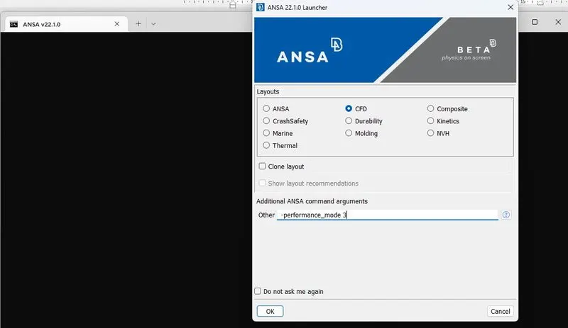
- Start ANSA using the CFD Layout and the -performance_mode 3 argument.
- Create a new file work environment
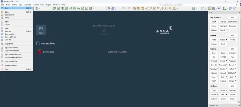
- Import Turbocharger file from location in your computer using file menu
- Ensure the geometry is in TOPO module
- Check for geometry inaccuracies by switching between Entity and PID modes.
- In the PID mode, it is observed that faces are overlapping
- Navigate to the List menu bar in the ribbon and click on P to see list of assigned PIDS
- Although, all the PIDs have same name, the color property can be used to identify each part
- As faces are overlapping, the glitches have to be rectified.
- By switching on and off the PIDs, it is observed that the overlapping pink face is not required
- To resolve it, either the pink PID is deleted or switched off.
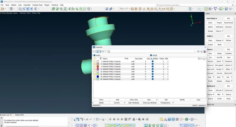
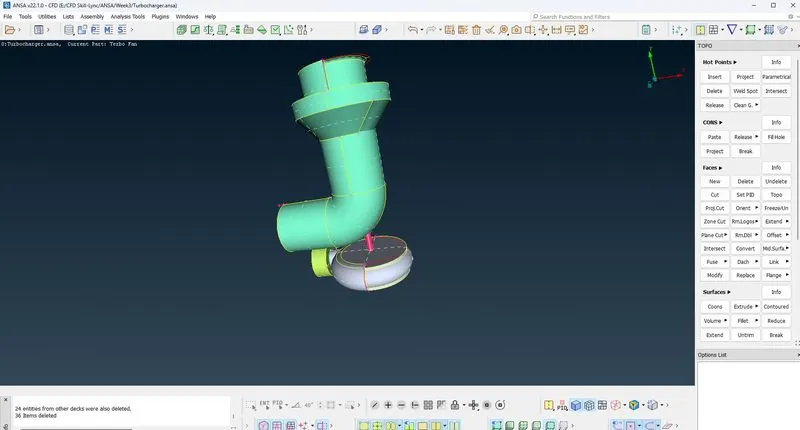
- Next, use the checks tool in the ribbon to check for geometry errors
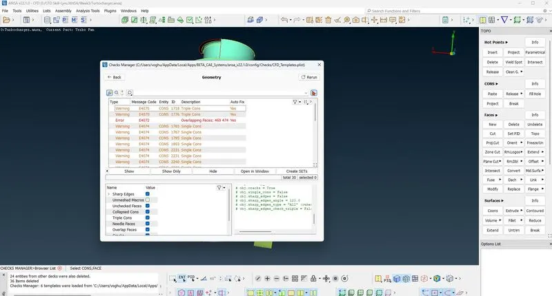
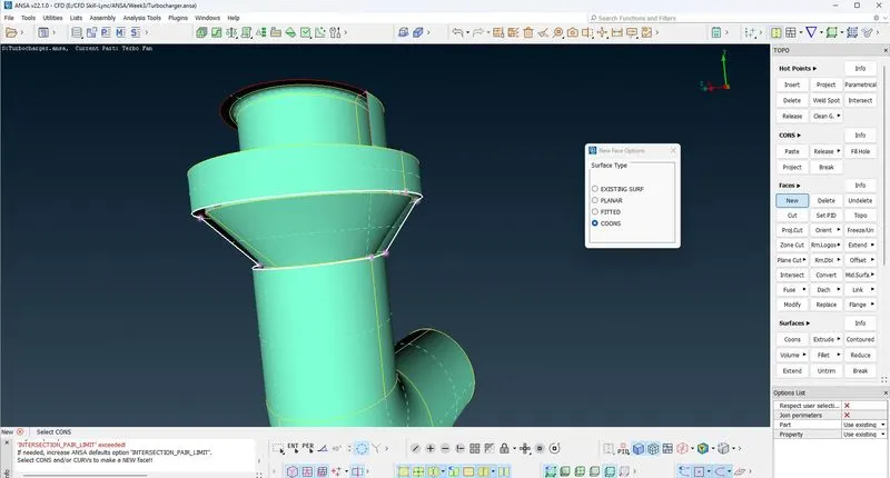
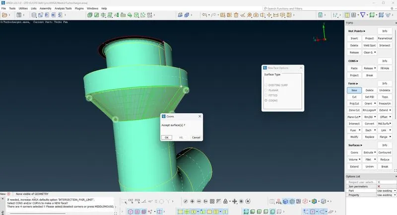
- Resolve the single CONS errors in the compressor outlet by deleting the unwanted face
- Create a face to finally resolve the single CONS error on the compressor outlet
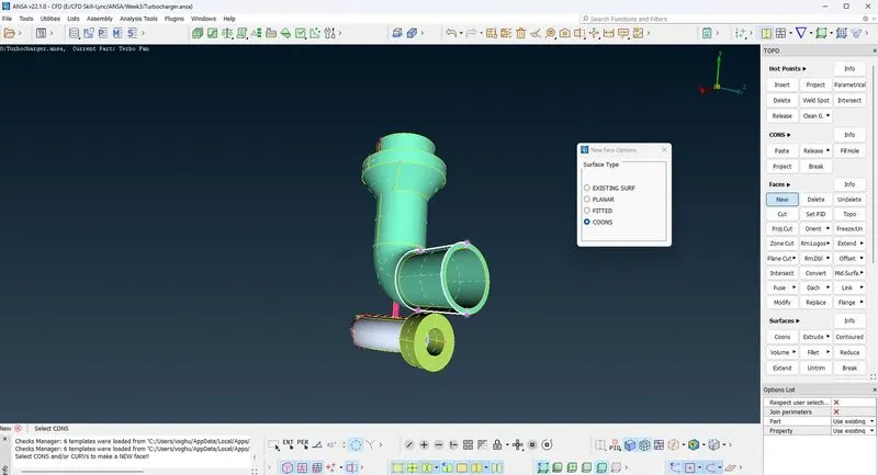
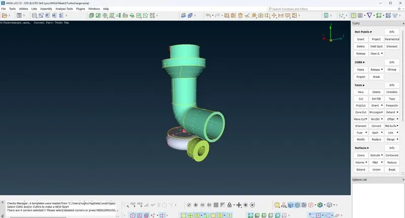
- Using the wireframe mode, there are further single CONS in the Blade stage 2
- Using the intersect option, delete unwanted faces
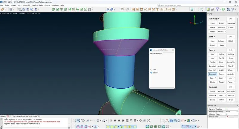
- Upon review, it appears the near the Blade stage 2, there are unwanted curved surfaces
- Create a cut, delete unwanted faces and create a new face to fix the geometry
- Using the wireframe mode, there are single CONS found in the Blade stage 1
- Using the transform option in the curves module function, create curve between points
- Using the new face in the face module function, create a face as shown below
- Delete the curves created after successfully removing the CONS error
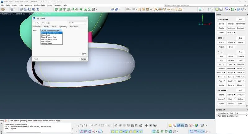
- Using the wireframe mode, single CONS were found in the Turbine section
- Insert a hot point at a point on the single CON
- Navigate to the Transform menu in the Utilities menu bar and select COPY
- Next select the entities, accept.
- And in the dialog box, select symmetry and then mirror three points plane from the drop down menu
- Select the hot points and accept
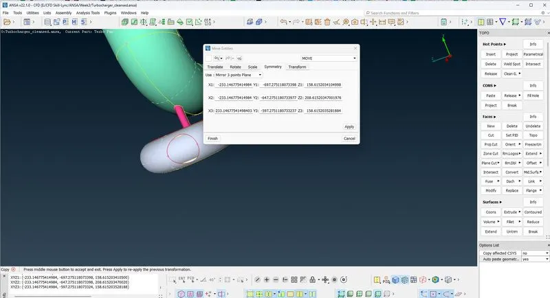
- Using the fill hole, create a face on the hole
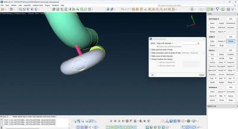
- Do TOPO to connect the face
- Perform error checks again on geometry to see that single CONS errors are resolved
- Then perform checks on intersections errors.
- This time, there were some intersections errors on the blades
- Using the Not Boolean operation, isolate the compressor casing.
- Next, lock it and perform TOPO. This operation reveals presence of Triple CONS
- Using Not Boolean operations, remove the blades and delete the extra faces
- Remove the middle section of shaft and delete the overlapping faces
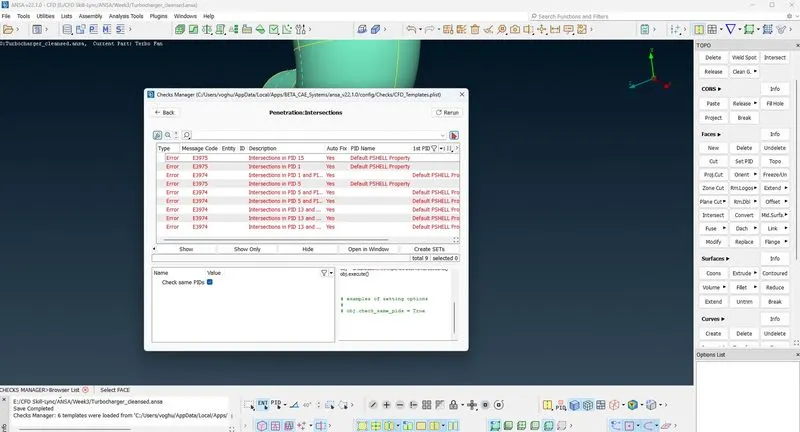
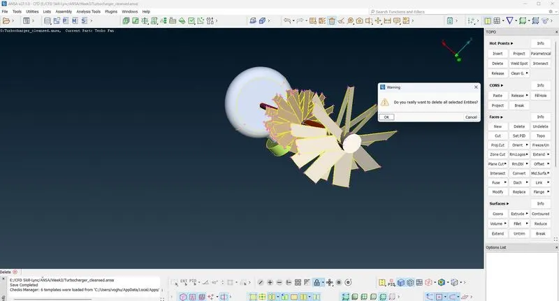
- Perform final check geometry and intersection errors
- Next save the cleansed geometry in preparation for surface and volumetric mesh.
- Then rename the assigned PIDs
- Perform surface meshing. However, we need to create new surfaces at the bottom of the Turbine casing, inlet casing cover Compressor inlet and outlet to define volume
- Navigate to the Mesh module and select classic mesh module
- Conduct surface meshing for the blades and shaft rotor since they have the same target length of 1mm
- Using Auto CFD function in the perimeter module with a 1mm target length
- Define a spacing parameter of 0.5mm minimum and 1.5mm maximum since target length is 1mm
- Using the perimeter and macros options, a mesh is obtained with a total element of 328872
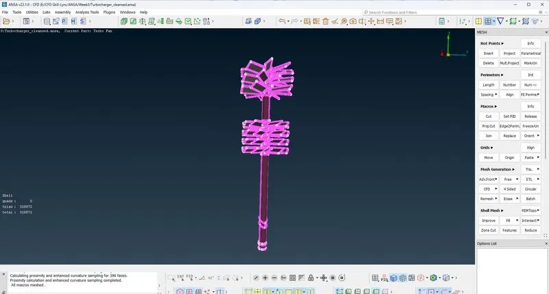
- Next conduct surface mesh for impeller using 2mm target length with a spacing of 1mm – 3mm
- A total of 10019 elements mesh were generated for impeller meshing.
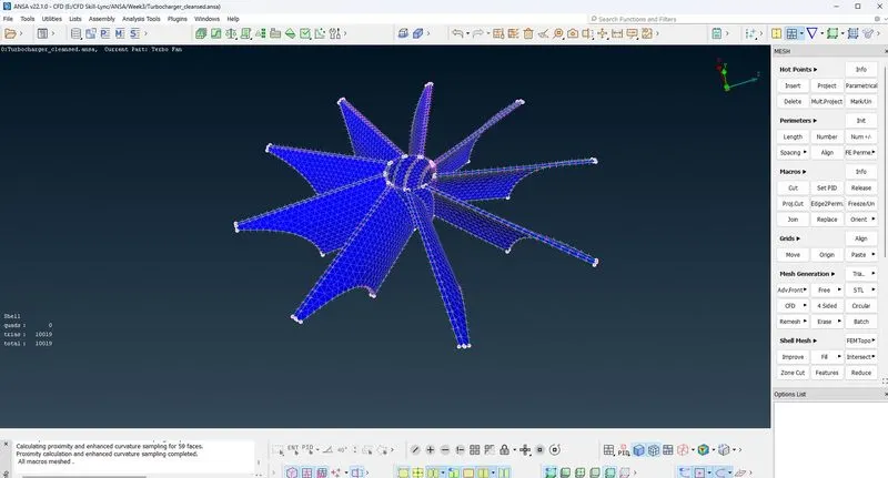
- Conduct surface meshing for the Turbine casing, Compressor casing and inlet casing cover since they have the same target length of 5mm
- Using 5mm target length with a spacing of 4mm – 5.5mm
- A total of 144638 elements were generated.
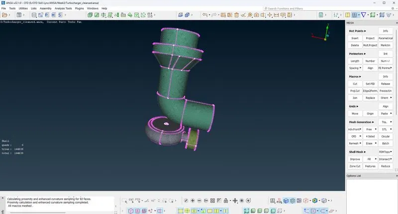
- However, when meshing was done for the entire geometry, there were 6 unmeshed surfaces
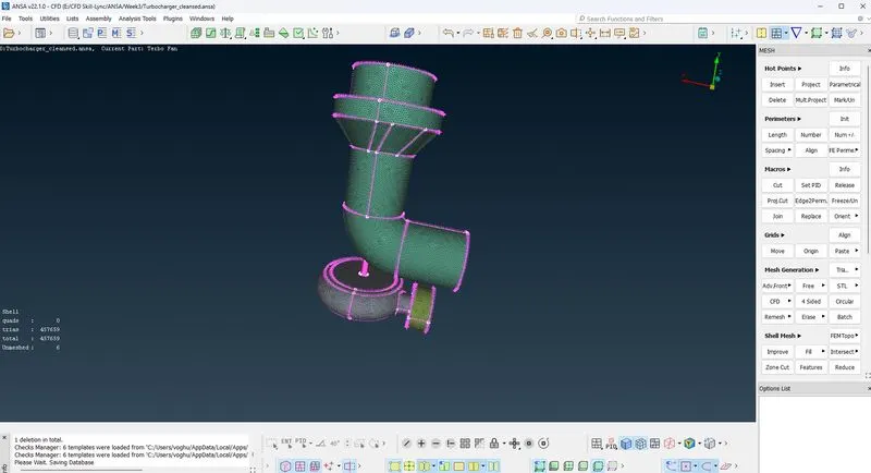
- Next conduct the above meshing with the freeze option
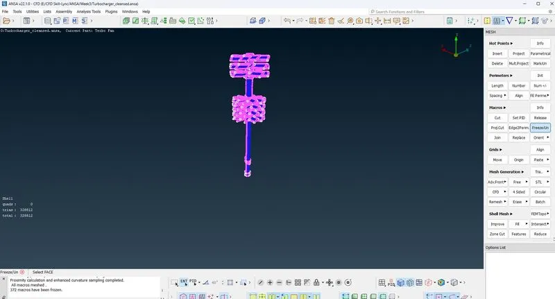
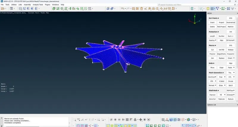
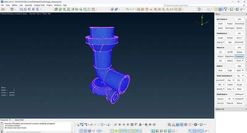
- Next unfreeze and conduct volumetric meshing
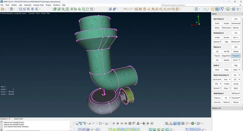
- Navigate to the volume mesh module and use the define module function
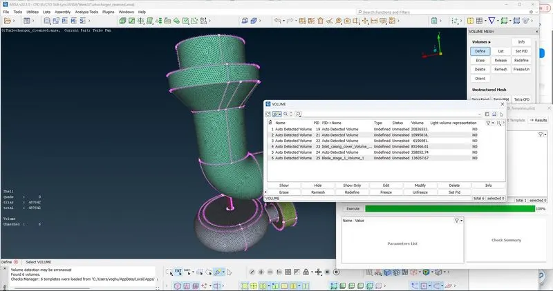
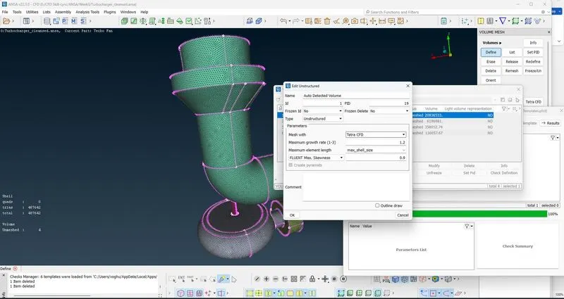
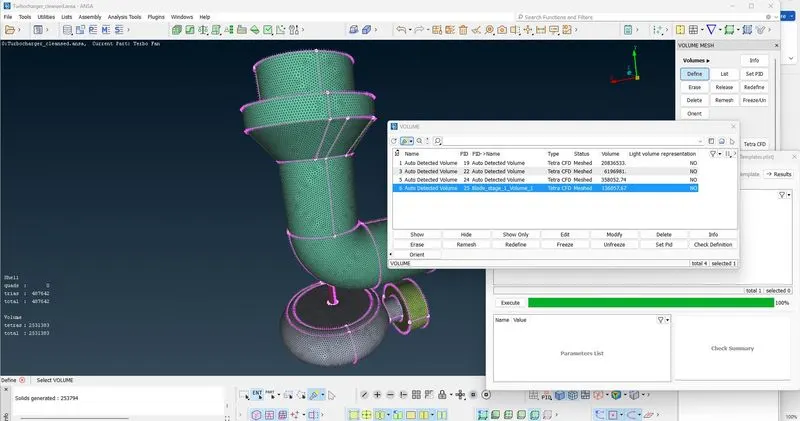
- Delete all external volumes
- Conduct the mesh using Tetra CFD
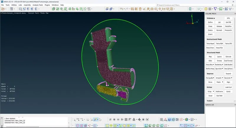
Result Comparison
A total element of 328872 elements were generated for the blades and shaft
A total element of 10019 elements were generated for the impeller
A total of 144638 elements were generated for the Turbine, Compressor and inlet casing covers
The volume mesh generated 2531383 elements