Week 3 Challenge : CFD meshing on Turbocharger
Aim:
For the given model, check for the geometrical errors to make appropriate volumes.
Create and assign PIDs.
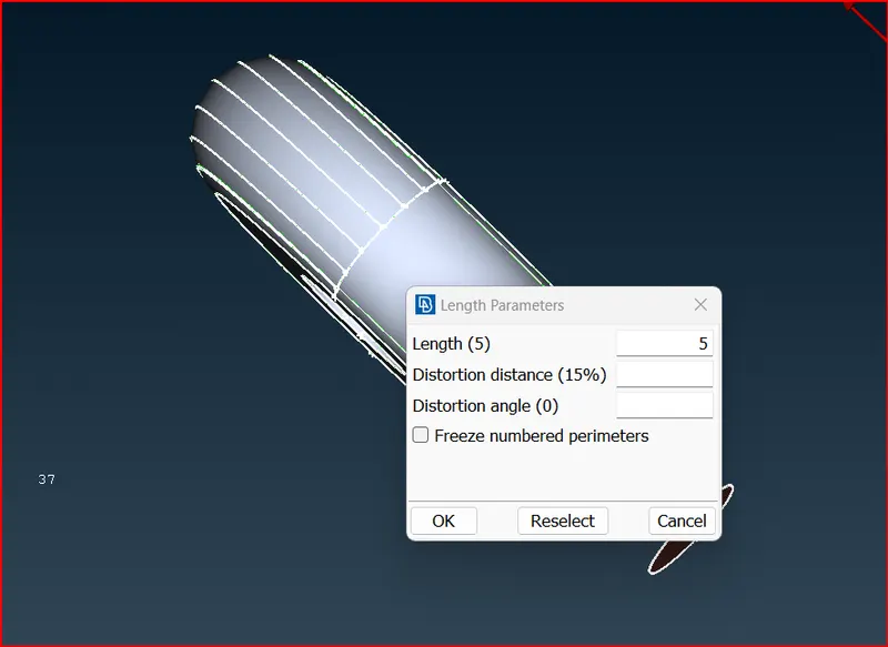
Perform surface mesh with the given target lengths as per PIDs.
- Blade stage-1 = 1 mm
- Blade stage-2 = 1 mm
- Impeller = 2 mm
- Shaft rotor = 1 mm
- Turbo casing = 5 mm
- Compressor casing = 5 mm
- Inlet casing cover = 5 mm
Perform Volumetric mesh for the required volumes as shown in the videos.
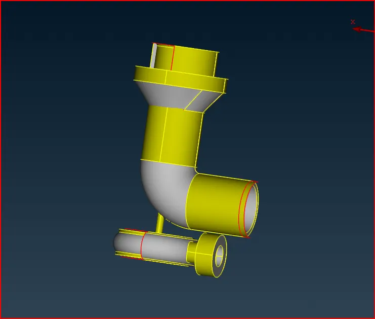
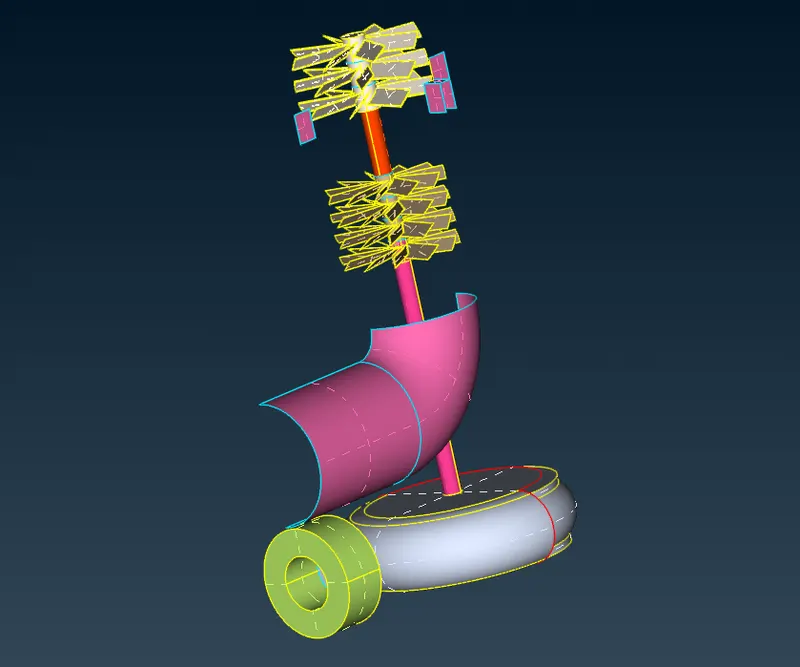
Given geometry:
Performing Geometry checks:
Perform Topo Check

The presence of pink bleachings is due to overlapping surfaces.
Hide the main surface using not command and here we see the extra surface and we should delete it.
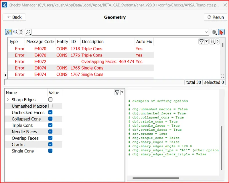
Go to Tools>checks> geometry> sleelct the checks that needs to be performed >click on execute.
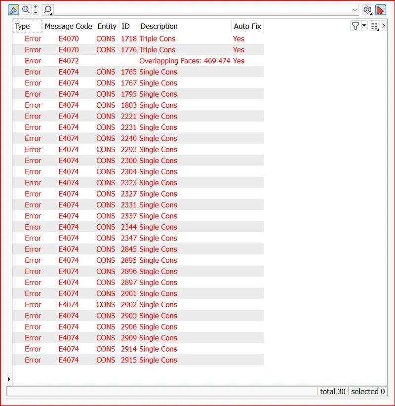
Errors found in the geometry:
View of single cons in wire frame mode:
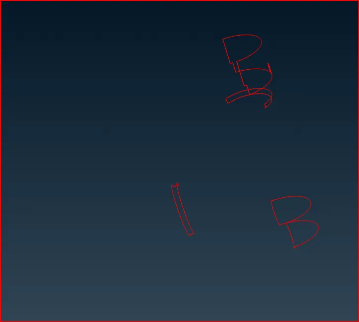
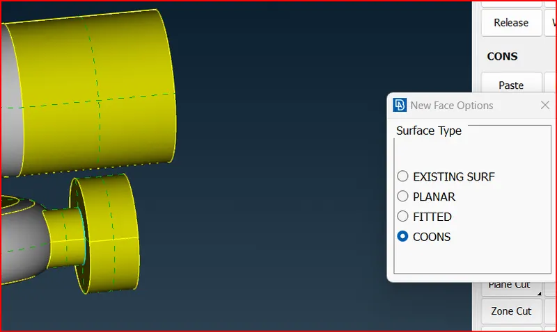
Created new surface using coons option
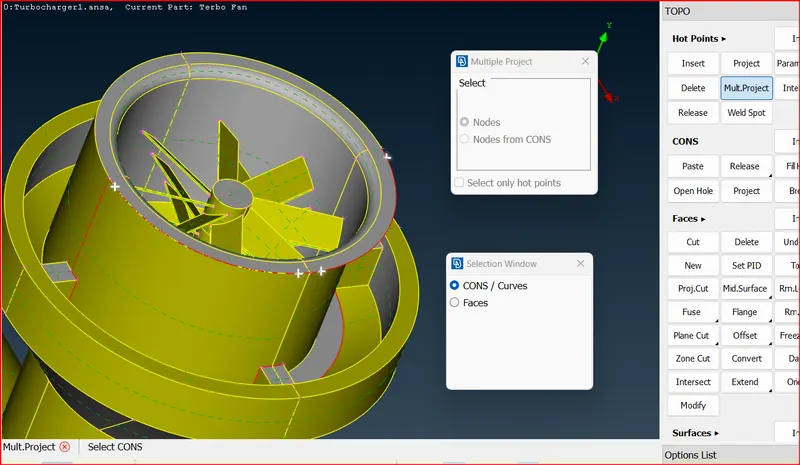
Using Multiproject option project the hot points and create small new surfaces.
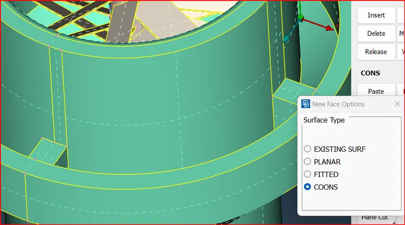
Created surface
Use intersect option to rectify the below error.
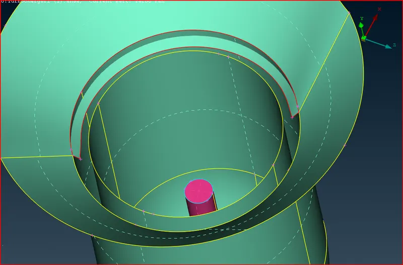
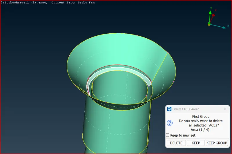
After deleting the extra surface
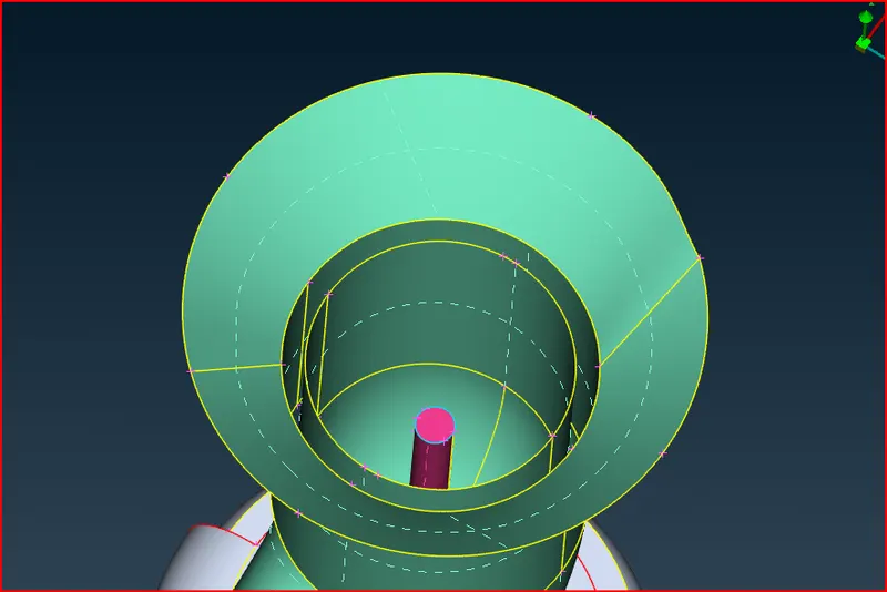
Creating new surface after creating required hot points
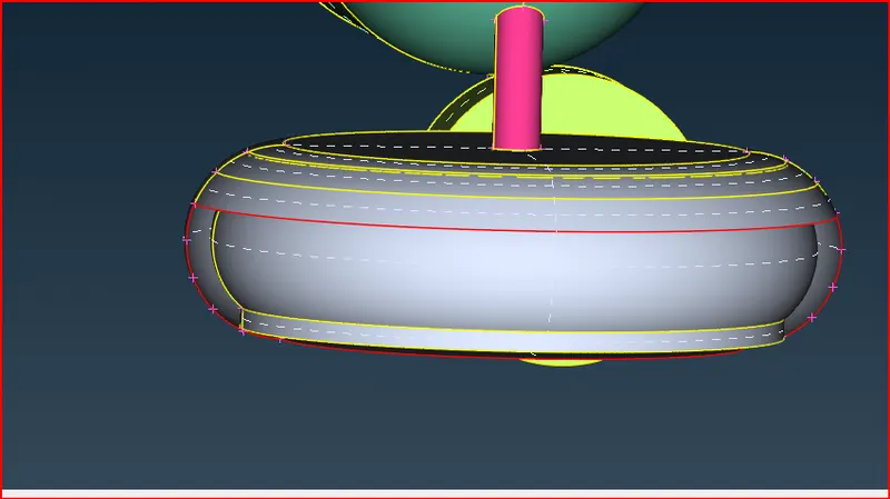
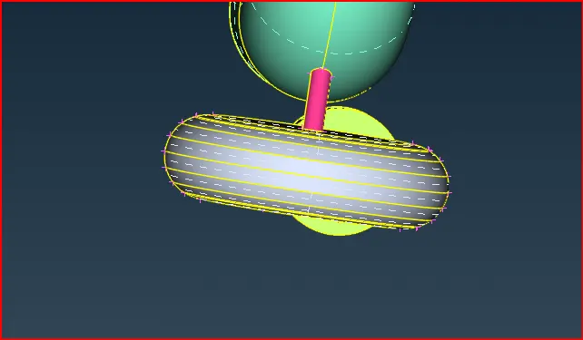
Triple cons:
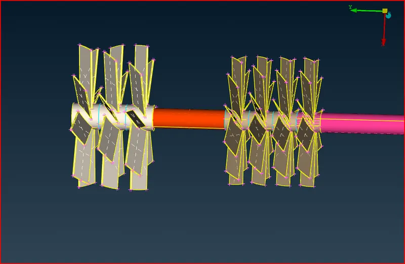
Delete the inner surfaces.
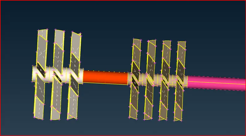
Overlaped surface
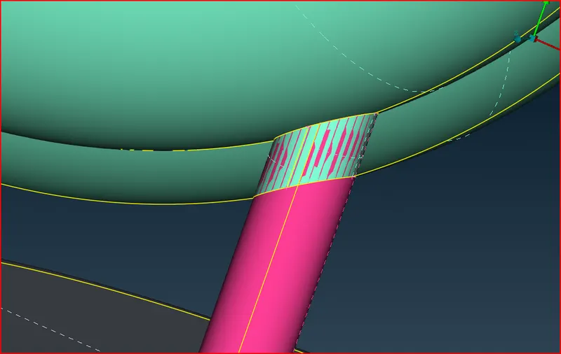
Now after deleting we restore all the surfaces and perform geometry checks

One triple con is present that is essential.
Now topo clean up is complete.
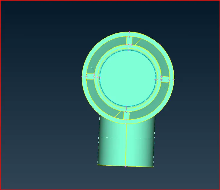
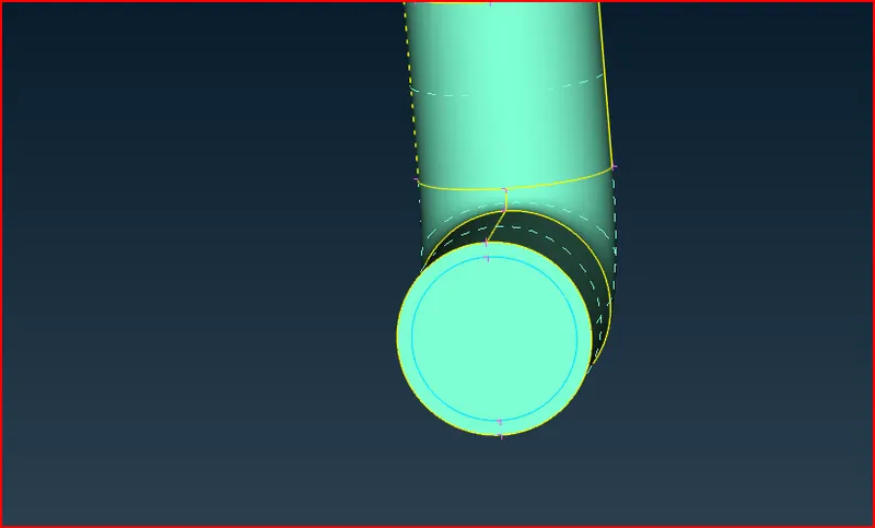
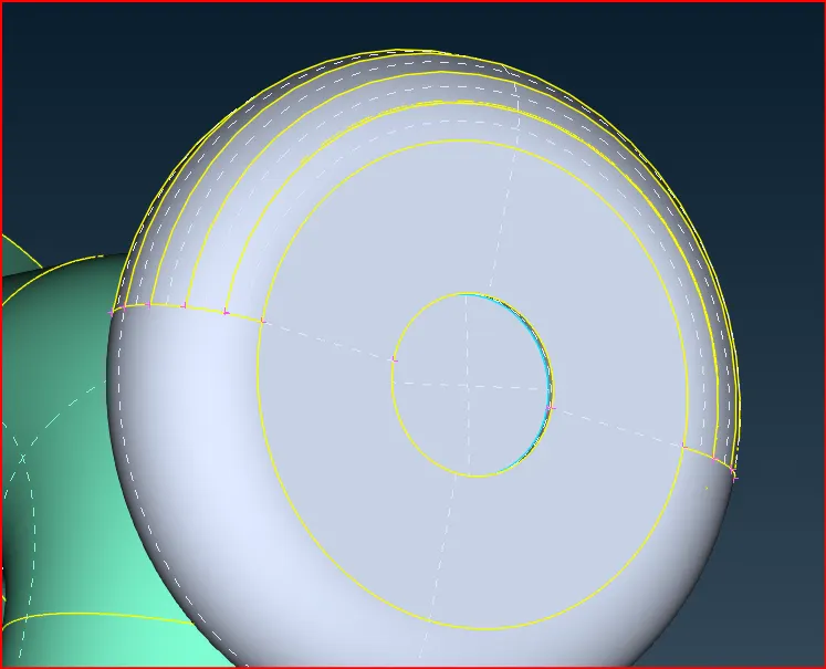
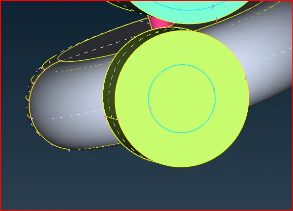
Close the geometry to do Volumetric mesh:
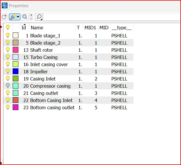
PID Management
Outer casing
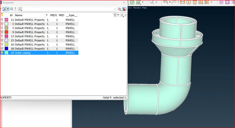
Outer casing Inlet
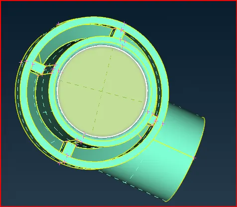
Outer casing outlet
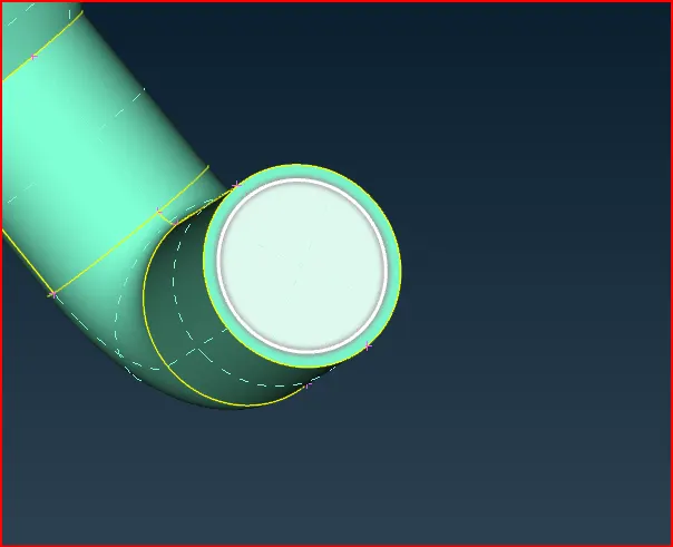
Bottom casing
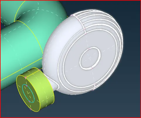
Bottom casing Inlet
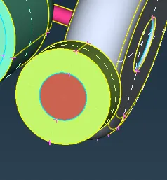
Bottom casing Outlet
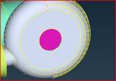
Bottom Feature
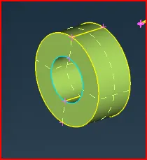
Assign Vertical shaft and top, bottom and Middle blades accordingly
Using compress option delete the unwanted PIDs.
Meshing:
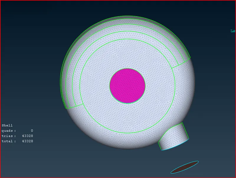
Surface Meshing
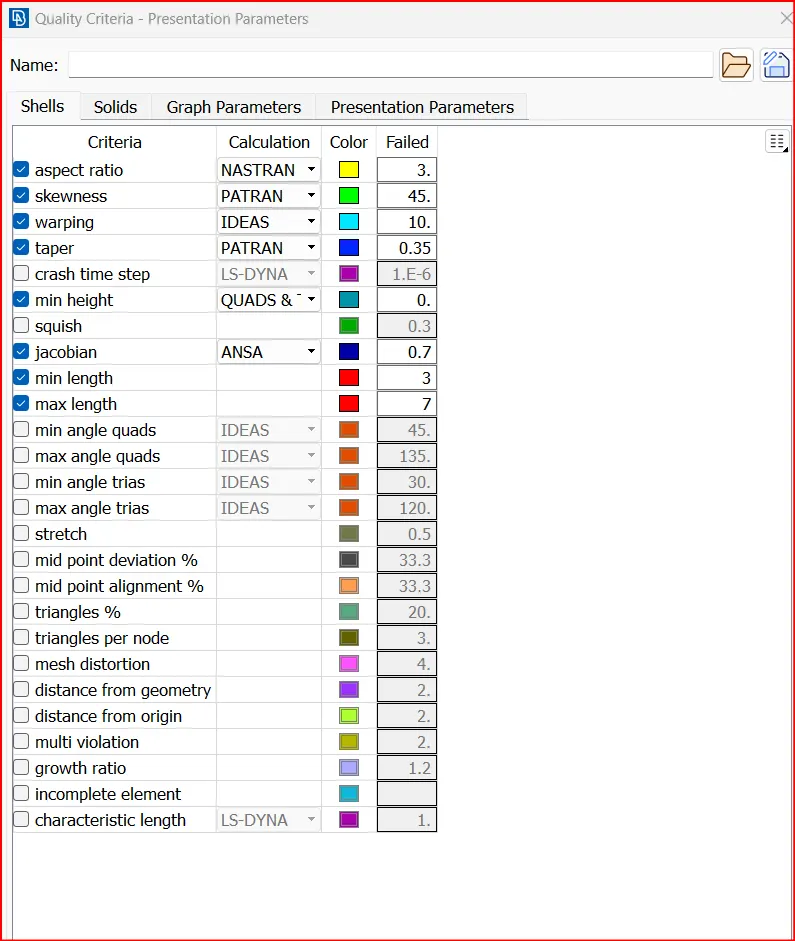
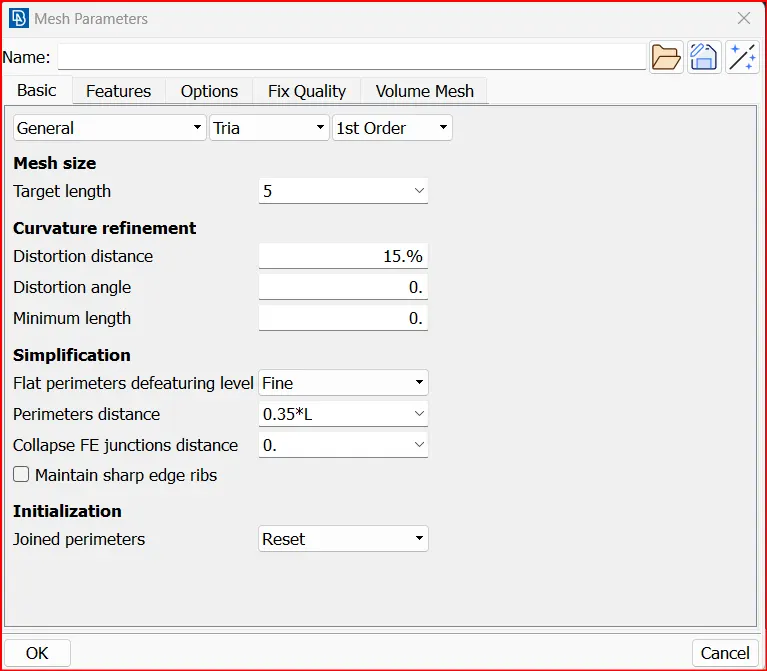
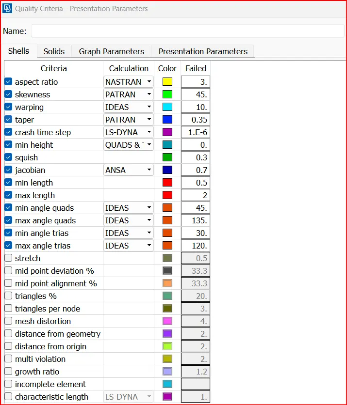
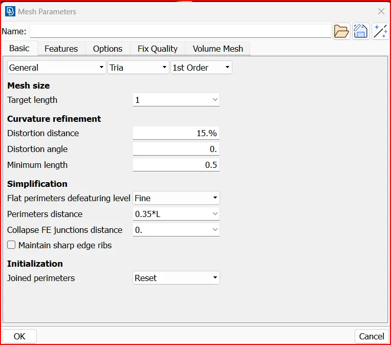
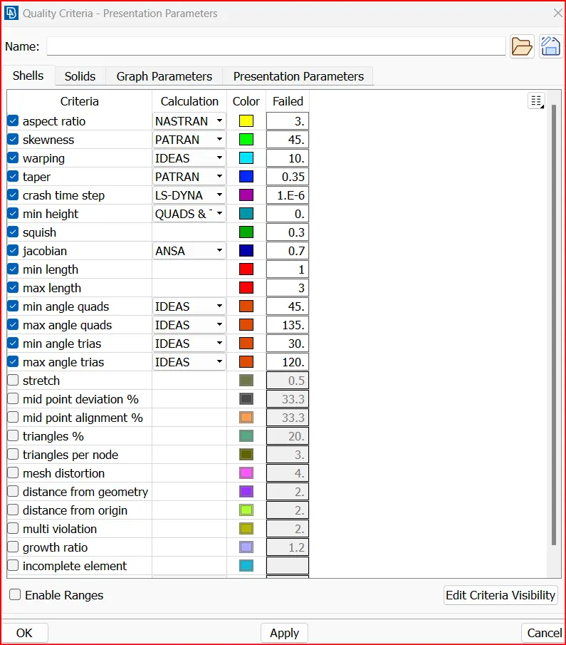
Mesh criteria:
- Blade stage-1 = 1 mm
- Blade stage-2 = 1 mm
- Impeller = 2 mm
- Shaft rotor = 1 mm
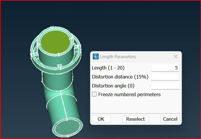
- Turbo casing = 5 mm
- Compressor casing = 5 mm
- Inlet casing cover = 5 mm
Compressor casing, inlet and outlet cover:
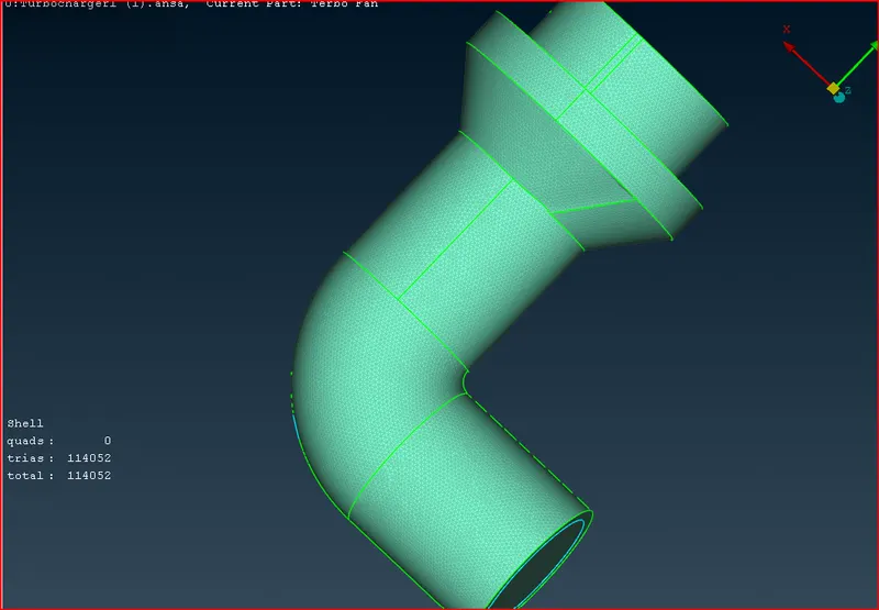
Turbo casing, inlet and outlet
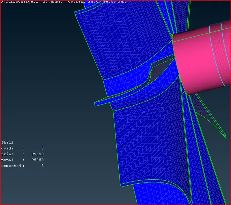
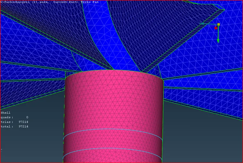
Blade Stage-1 and stage-2
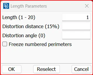
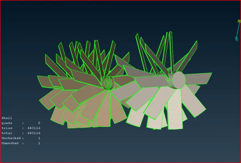
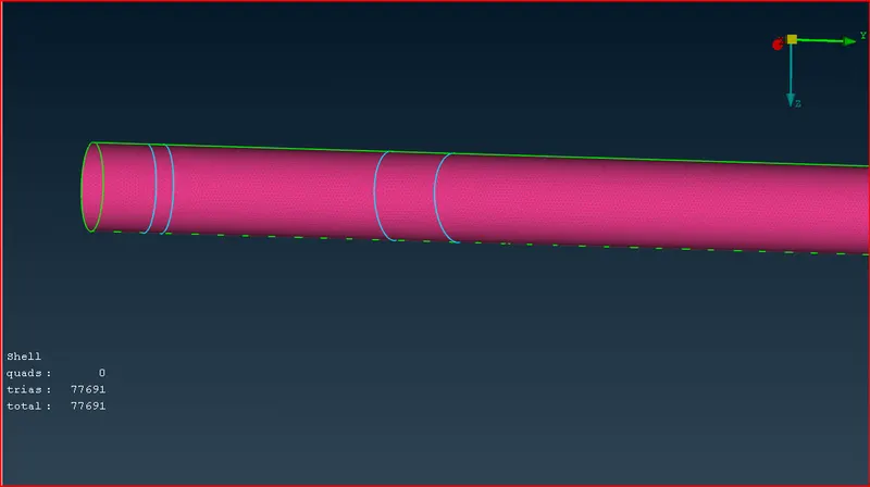
Impeller
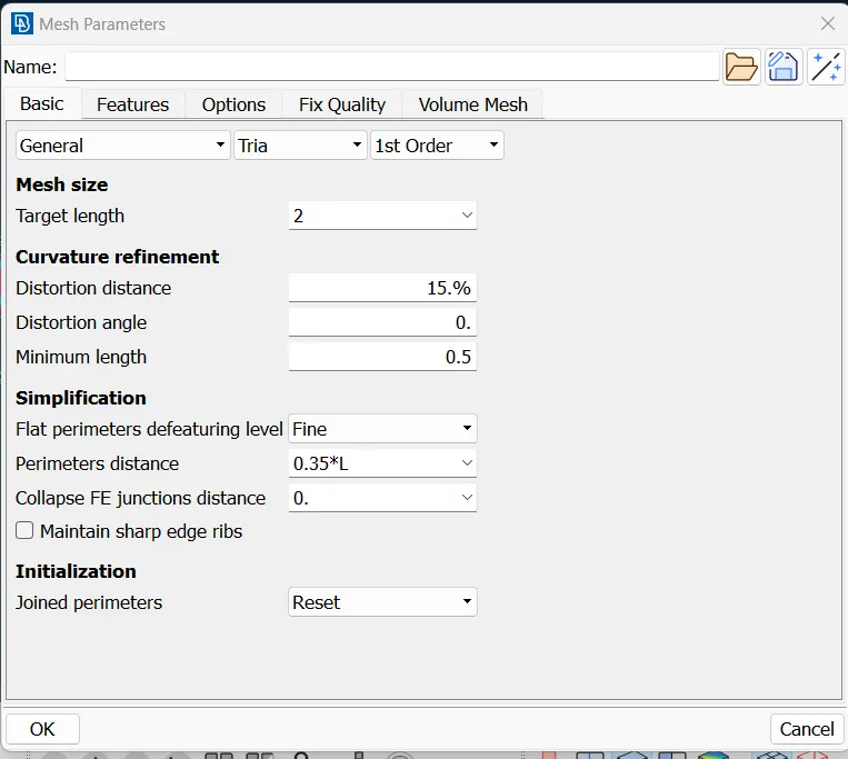
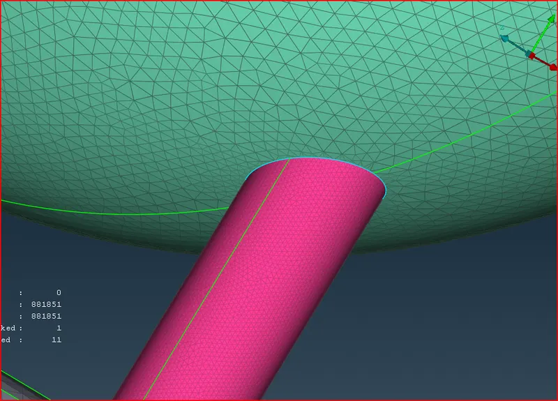 .
.
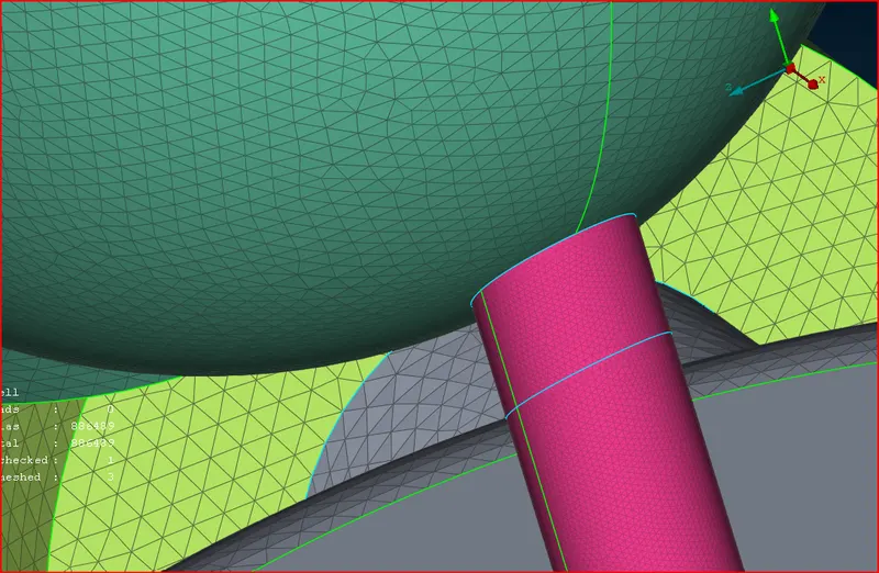
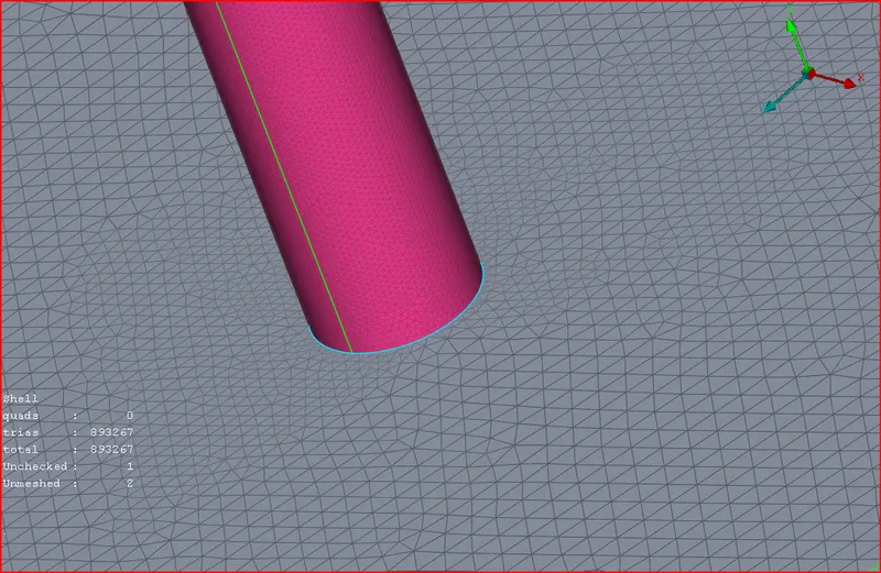
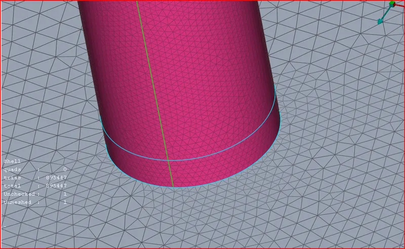
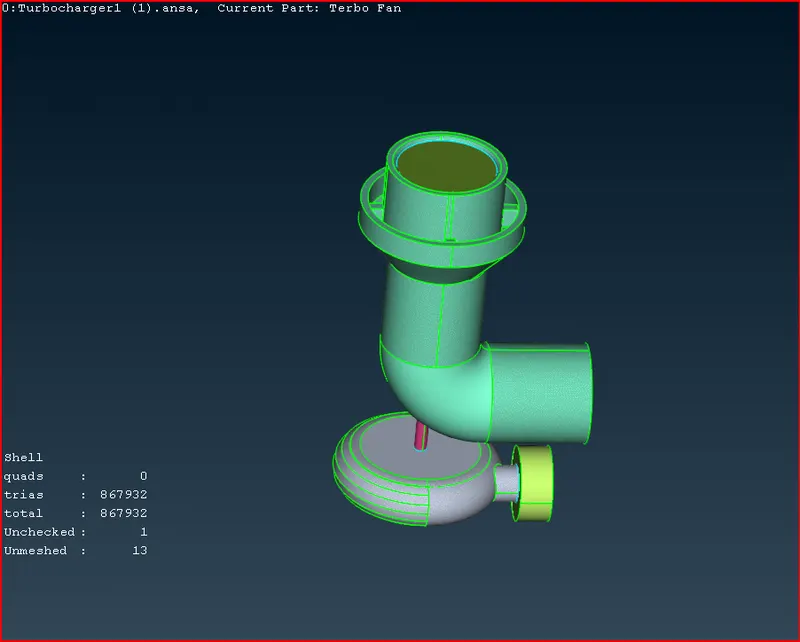
Final mesh
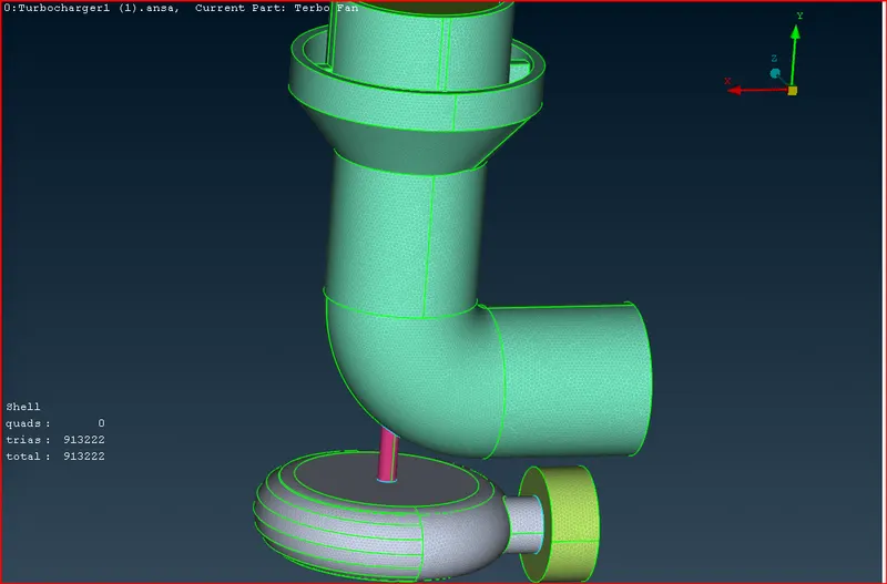
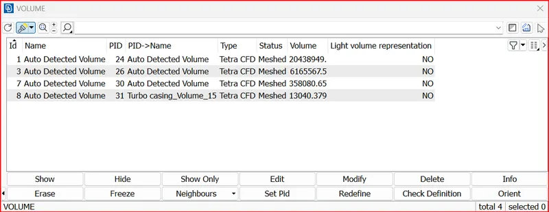
Volumetric Meshing
Since we are meshing this component for cfd applications, we will be meshing the volumes which are not occupied by the parent geometry thickness.
meshing is done only in the region where the fluid will flow.
Defining 3d Volume:
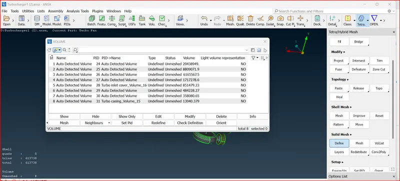
Required Volumes for Meshing: This is the volume where fluid flows.
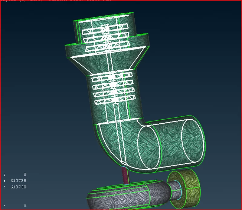
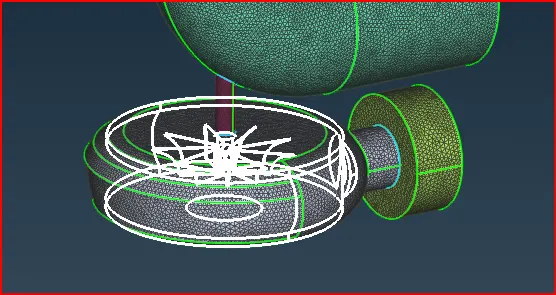
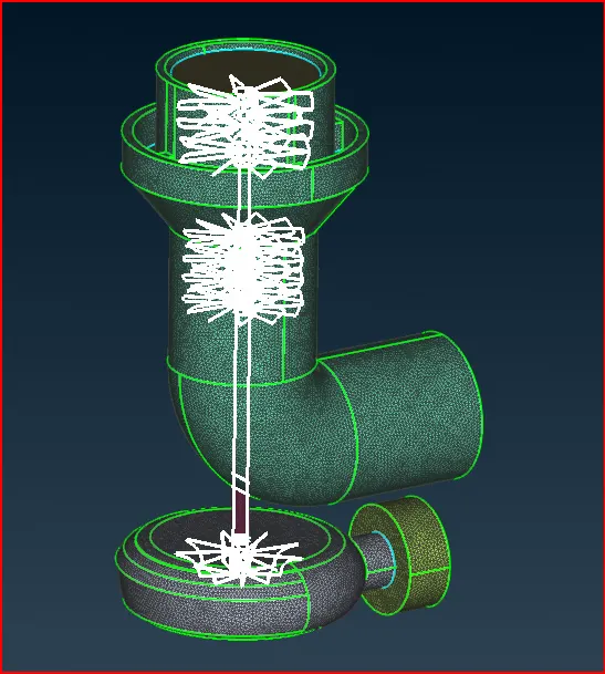
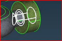
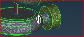
Volumes to be deleted: These the parent geometry thickness volumes.
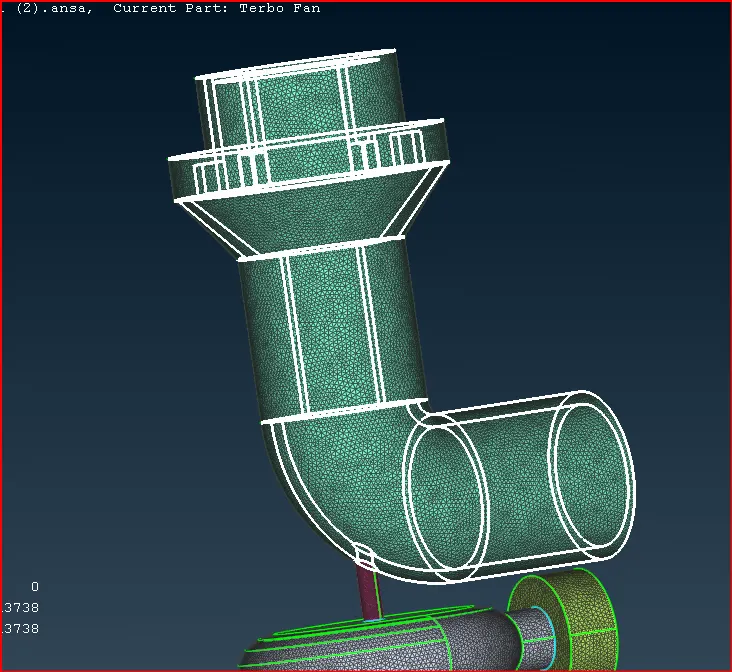
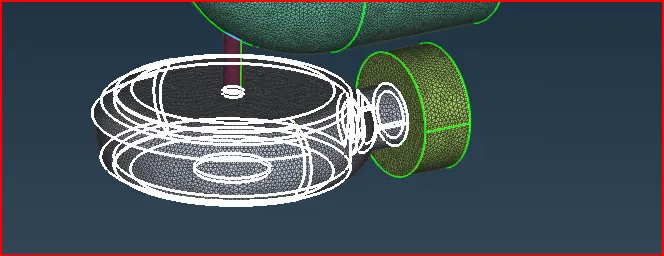
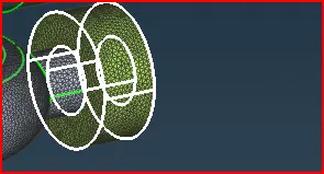
Final volume
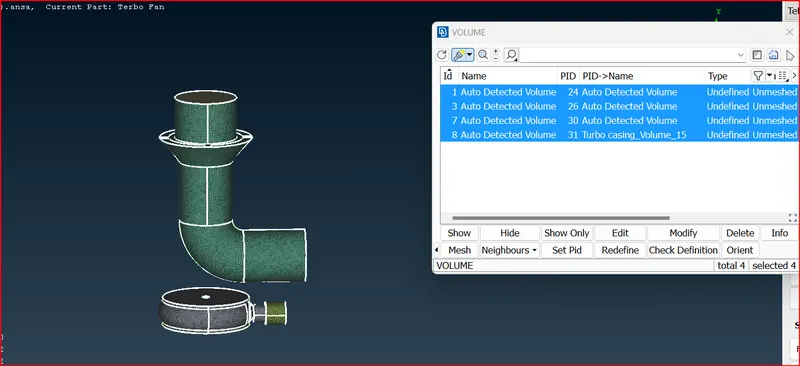
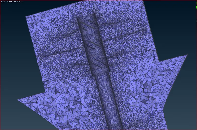
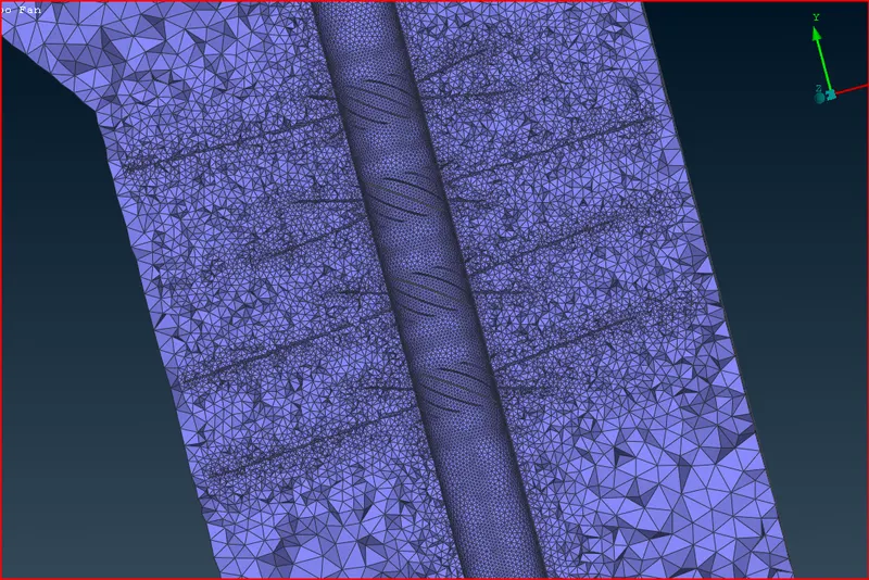
AFter volume meshing
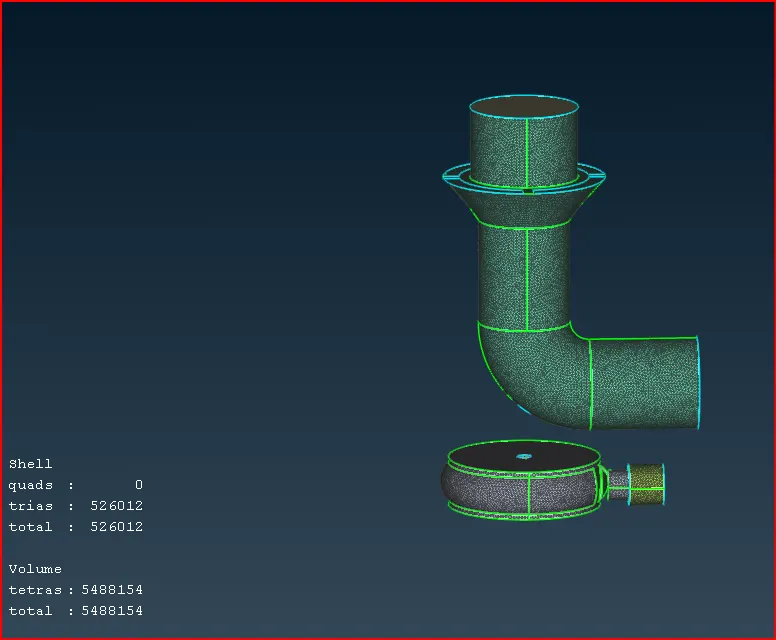
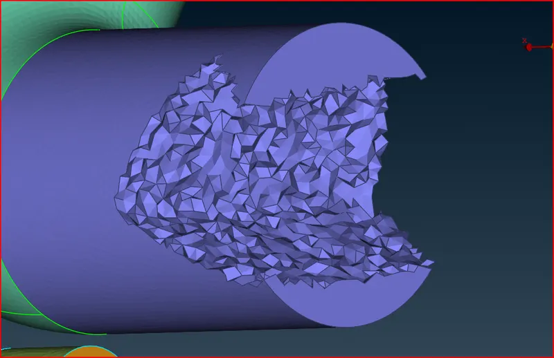
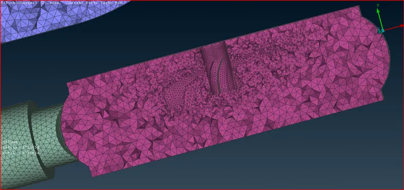
Tetra Mesh elements
Conclusion
Volumetric mesh is done on the given turbo charger Model.
we observe that in volumetric meshing the mesh size gradually increases from 1mm to 5 mm near the blade region.