Week 3 Challenge : CFD meshing on Turbocharger
CFD Meshing on Turbocharger
Inroduction:
The objective of this project is to CFD meshing on turbo charger by using some methodologies learn by video lectures and live sessions.Basically turbocharger is nothing but in an internal combustion engine,a turbo charger is a forced induction device that is powered by the flow of exhaust gasses.It uses this energy to compress the intake gas,forcing more air into the engine in order to produce more power for a given displacement. In preprocessing of a turbocharger is known as meshing.There are three types of basic methodologies used in the model anaysis.Thare are,
- Pre processing
- Solving
- Post processing
Pre processing:
Pre processing is nothing but before initiating an actual task it is important to prepare for the task in order to achieve the desired result.This is true in the simulation word too.Every CAE simulation requires some preparation to be done before it can be numerically st up and performed.This step is called Pre processing.For the given project we are using ANSA for meshing a given geometry.
ANSA:
ANSA was initially stands for 'Automatic Net generation for Structural Analysis',but the software has gone beyomd that very quickly.Actually ANSA is a computer aided engineering tool for Finite Element Analysis(FEA) and CFD analysis widely used in the automative industry.It is developed by BETA CAE systems.
Basic procedure for meshing:
- Resolution adjustment
- Close all open surfaces
- Surface cleaning
- Assigning PID
- Applying meshing quality
- Meshing
Aim:
For a given model to do a surface and volume meshing by using ANSA software.Perform surface mesh as per given target lengths as per PIDs below,
- Blade stage-1 = 1 mm
- Blade stage-2 = 1 mm
- Impeller = 2 mm
- Shaft rotor = 1 mm
- Turbo casing = 5 mm
- Compressor casing = 5 mm
- Inlet casing cover = 5 mm
After completing surface mesh ,have to do volume mesh of a given model as per CFD meshing procedures.
Surface cleaning:
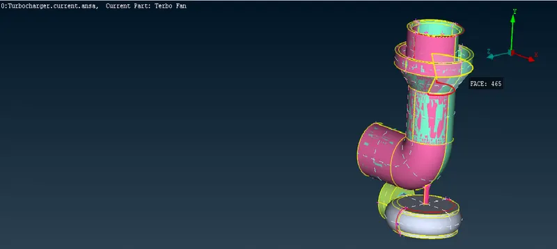
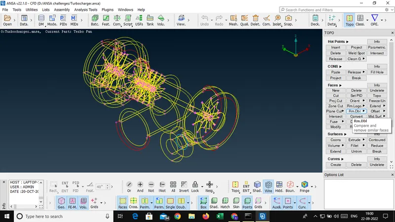
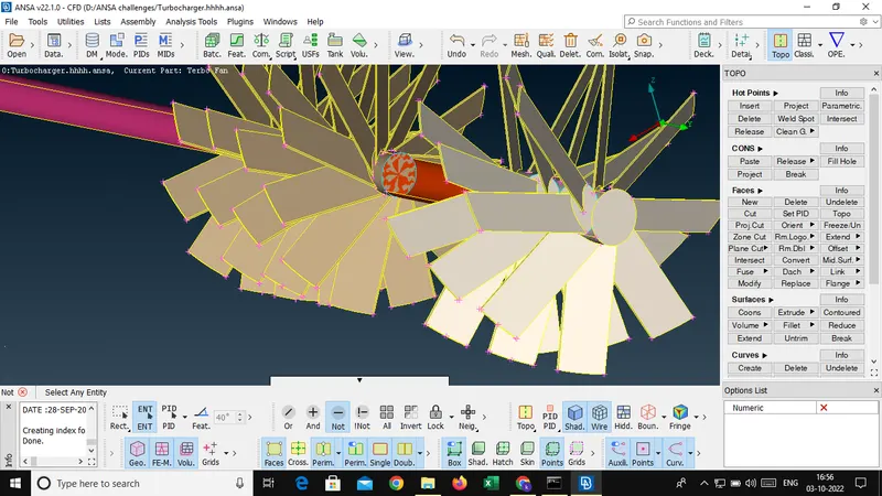
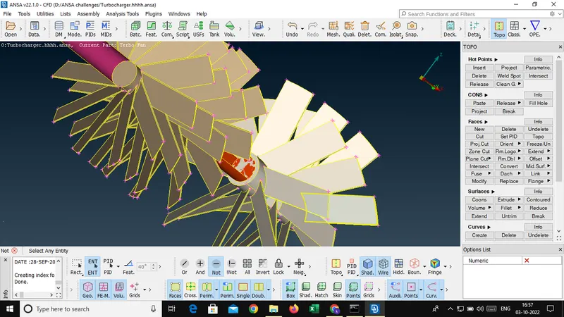
Surface cleaning is a methodology in meshing processes,it is the process to remove unwanted surfaces,red cons,creating neccesary surfaces inorder to obtain perfect mesh.
- Given geometry
- wire frame mode
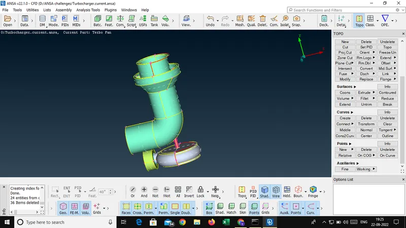
- Gliches removed
- Removing red cons
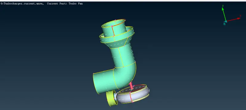
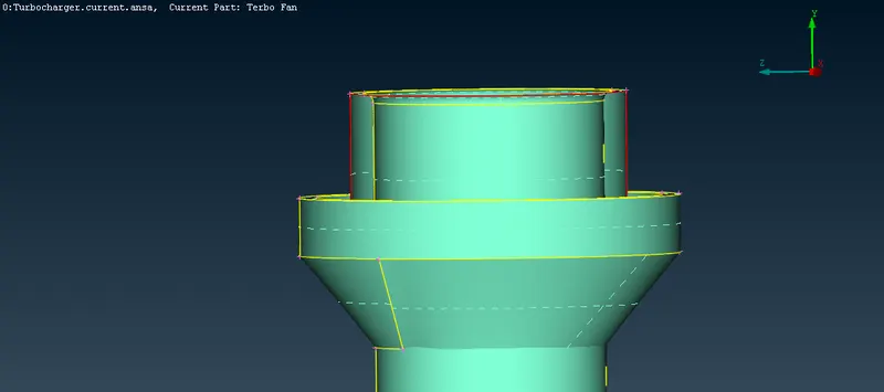
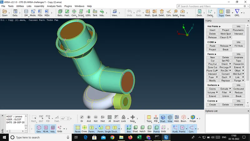
- Creating neccasary surfaces and Inlet outlet surfaces
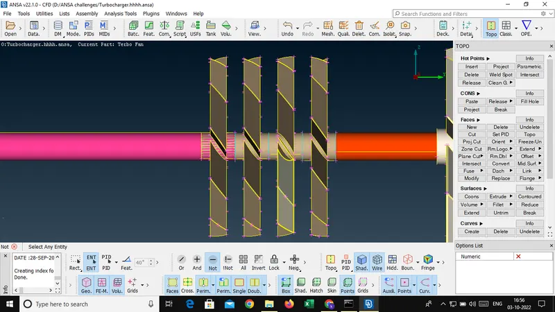
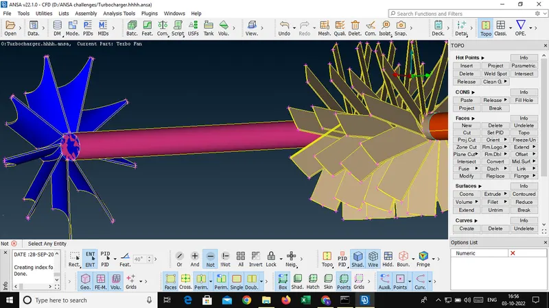
- Delete gliches
- What is the need to create Inlet and Outlet surface?
The need of inlet and outlet domain in the CFD analysis is to identify the flow direction and we should input the flow and fluid data as respected to the inlet and outlet region.Actually inlet and outlet regions are open when design design a model.but while meshing that region its required surface for meshing.without meshing we cannot be assign as ainput or output.thats why we create the region.
After removing all gliches,and creating all neccesary surfaces,after removing all red cons finaly we got following screenshot.
Assigning PID:
PID is stads for Property ID.It is used to identify the entities that is used for differentiate the entities for different kind of target length like that.

Geometry checking and error rectifing:
we shoud cheking the errors by using cheking option inorder to verify geometry errors.In this project had some errors that shown below,
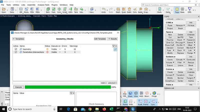
- Geometry errors
After correction of geometry errors the fig shown below,
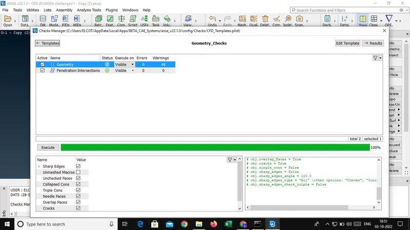
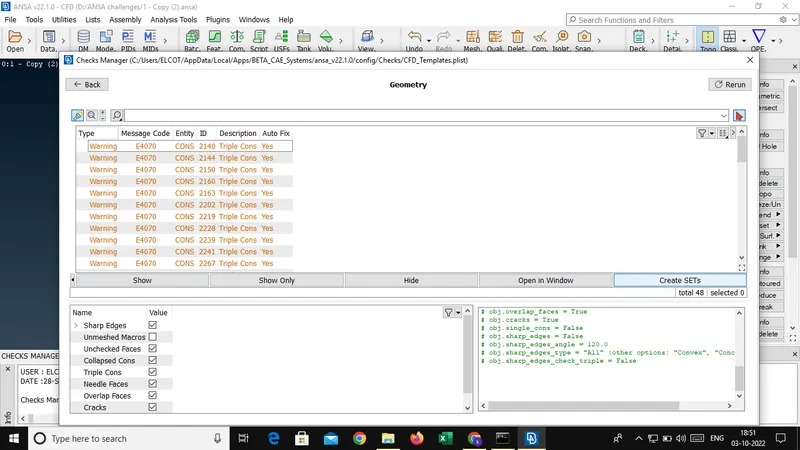
After clearing all geometry errors,there is have a 48 warnings.Actually it is triple cons warning.Triple cons are came because of created new surfaces for inlet and outlets like that.As shown below fig warning types,
- Intersection errors
The intersection errors are the penetration errors.There are 5 intersection errors are obtained while checking the error.After clearing intersection errors,below window shown.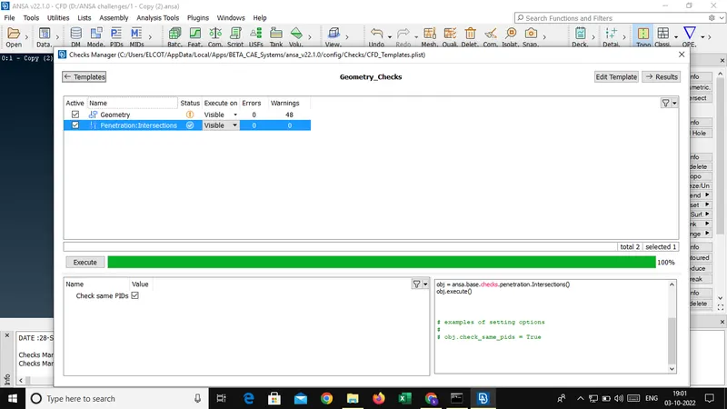
Surface meshing:
A surface mesh consists of a set of polygonal faces,often triangles,that,taken together,form a surface covering of the object.The advantage of a surface mesh is that is that it is fast to generate and works very well for visualization.
Quality meshing with different PID:
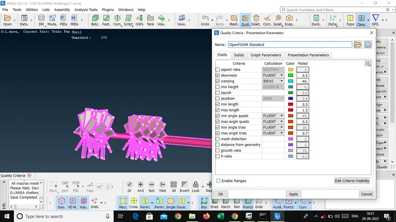
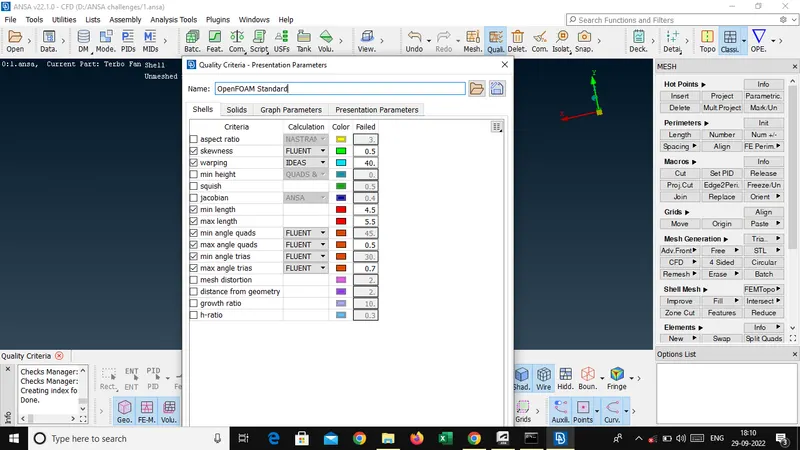
Applying all given quality criteria fig are shown below,
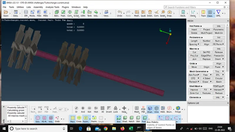
- 1 mm meshing
For blade stage 1,stage 2 and rotor shaft with 1 mm target length min amd max target length was applied by 0.5 to 1.5.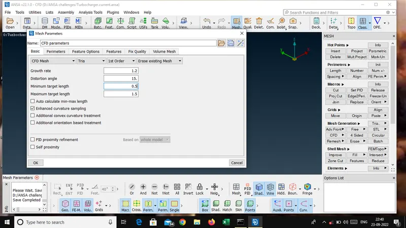
- 2 mm meshing
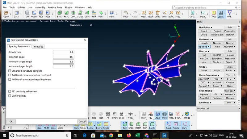
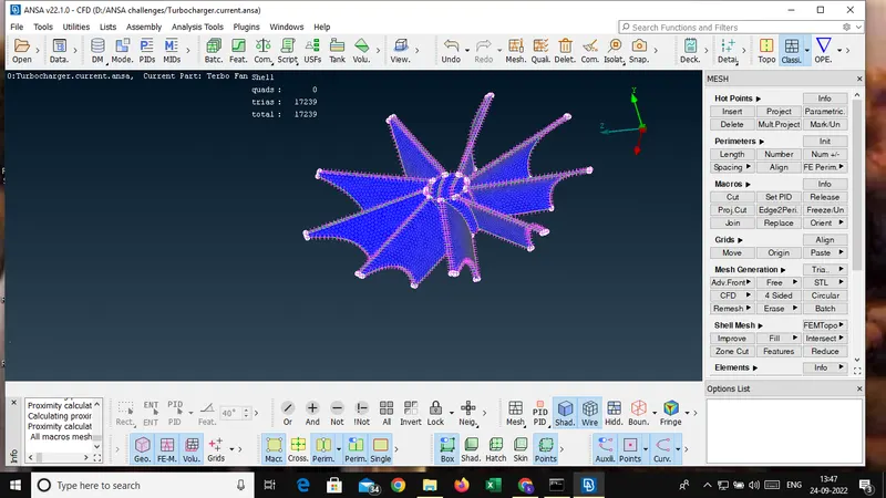
For Impeller with 2 mm target length min amd max target length was applied by 1.5 to 2.5.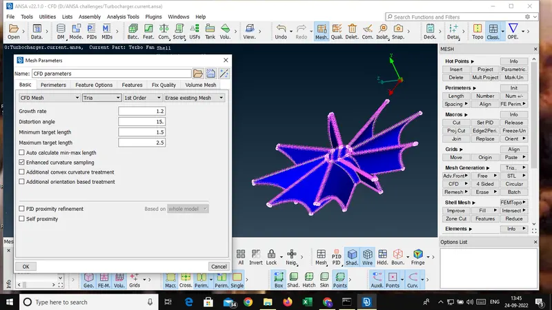

- 5 mm meshing
For turbo casing cover,compressor casing and inlet casing cover with 5 mm target length min amd max target length was applied by 4.5 to 5.5.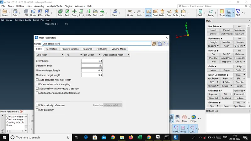
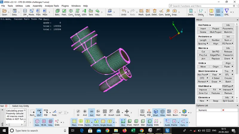
Volume meshing:
In 3D computer graphics and modeling,volumetric meshes are a polygonal representation of the interior volume of an object.Unlike polygon meshes,which represent only surfaces as polygons,volumetric meshes also discretize the interior structure of the object.
- Defining Volume meshing
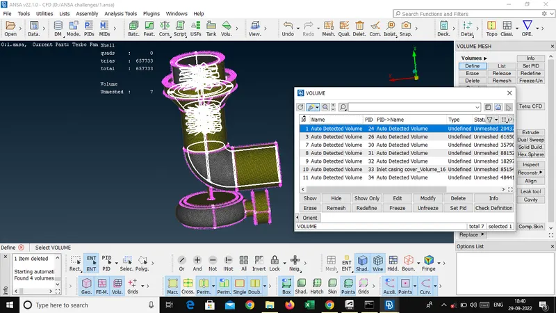
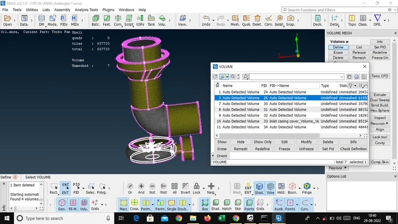
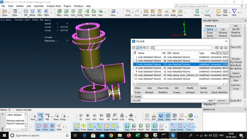
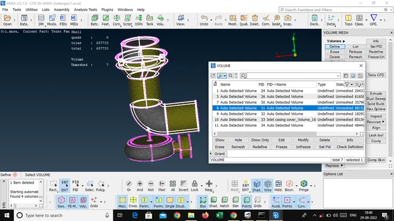
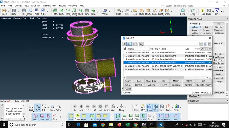
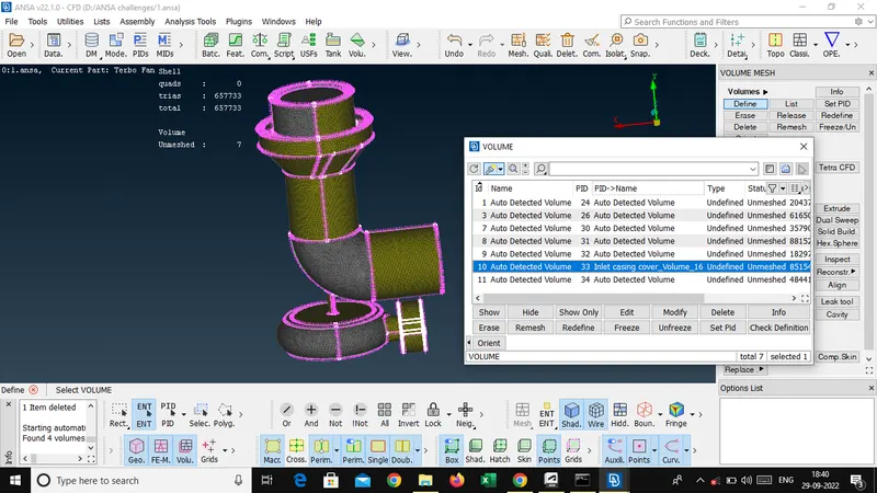
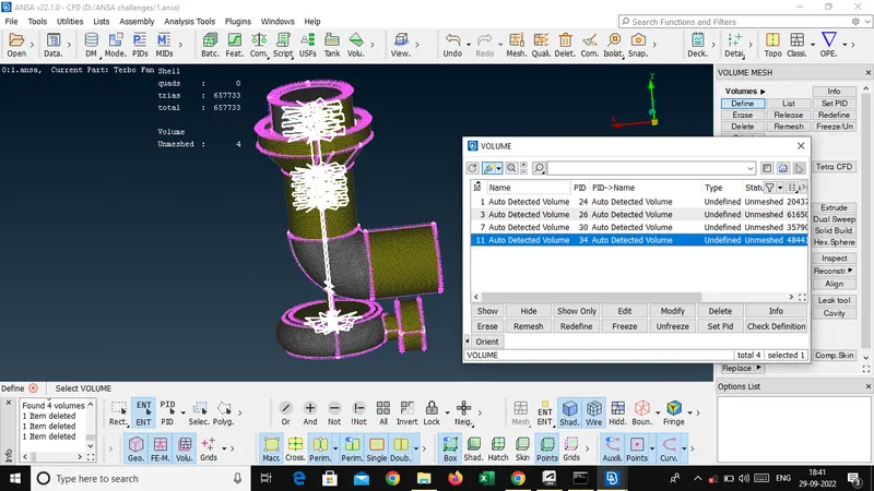
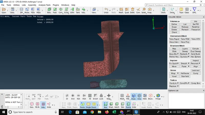
After applying define finaly meshing using tetra CFD meshing.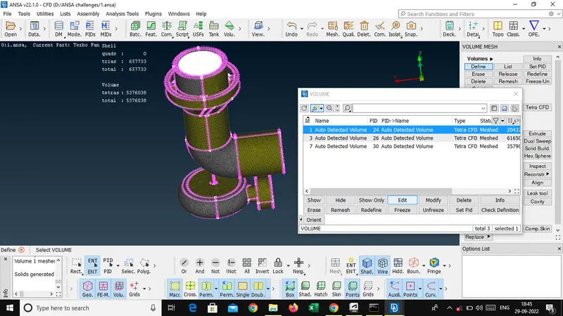
- Tetra CFD meshing
After meshing overall view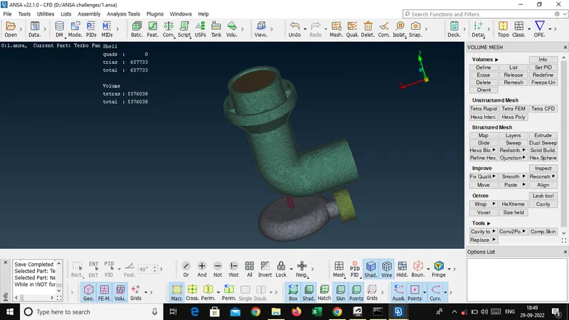
- Cut section view
Result:
After applying all required quality criteria finally we got shown below,
- Surface meshing
Succesful surface meshing with target length with own measurements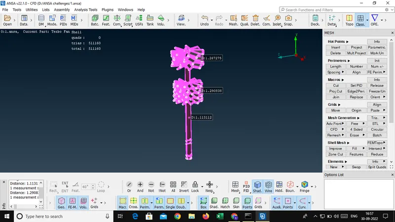
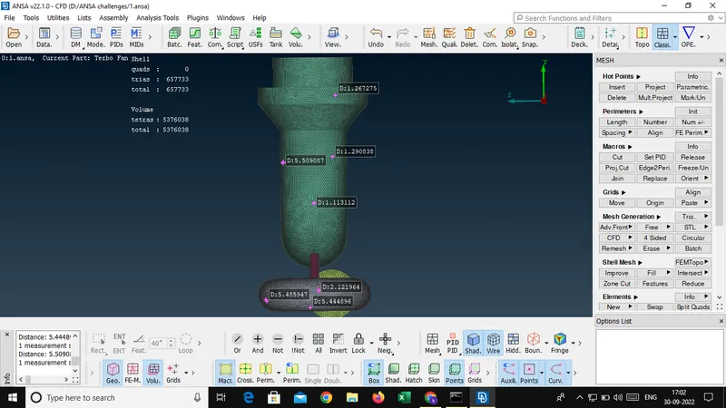
- Volume meshing
After succesful Volume meshing finally got fig given below,
Cut section view
Conclusion:
Finally succesfully obtained CFD meshing on a turbocharger as per given quality criteria as different target lenth with diffrent PID with the help of video lectures and live sessions.